
Chapter 19
Controlling Assembly Configurations and Display States
Assembly configurations enable you to control many things, including part configurations, suppression, visibility, color, assembly feature sizes, assembly layout sketch dimensions, mate values, and suppression states. In this chapter, you will learn about related topics such as design tables, SpeedPak, derived configurations, and display states.
Display states are a better performance alternative than configurations for controlling visibility and display styles in assemblies. Display state options are discussed at length in this chapter.
Using Display States
Display states enable you to change visual properties more quickly and efficiently than configurations in assemblies and drawings. Configurations can be slow to change from one configuration to another, whereas you can change between display states almost instantaneously.
Assembly display states can also control part display states, and different instances of a part in an assembly can use different display states. Display states can be used in parts, assemblies, and drawings. They can have a great impact on assembly and drawing work.
Assembly display states also have a huge impact on drawing performance. Whenever a drawing references multiple configurations of the same assembly, it rebuilds all the referred configurations and loads all the resulting models into RAM. So, for two configurations, two assemblies load, for three configurations, three assemblies load, and so on. Display states are much more efficient, because only one set of model data is loaded, with simple flags controlling the component visibility and appearance.
Controlling Display States and Configurations
Display states can be either independent of configurations or linked to them, depending on your settings. To control the display, you can use the Display pane that pops out when you click the double-arrow icon in the upper-right corner of the FeatureManager (or you can press F8). Figure 19.1 shows the Display pane in action, along with an assembly showing parts in different display states.
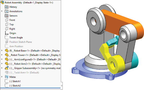
FIGURE 19.1 The Display pane and an assembly with parts in different display states
The column symbols for the Display pane are as follows:
 Hide or show state of the part
 Display Mode options for each component:
 Appearances
 Transparency
 Default Display
 Component/Part Color
Appearance overrides are settings that apply color to different aspects of model geometry. There is a hierarchy in which the appearances are applied, so an appearance applied to a feature may override or be overridden by another appearance applied to the part or an individual face. The appearance override hierarchy is summarized here, showing the highest priority at the top:
- Assembly
- Component
- Face
- Feature
- Body
- Part
So, you can read into this that the part appearance is overridden by every other type of appearance, and the appearance applied to the assembly overrides everything else.
If you override the appearance or display mode for a component in a subassembly, and the upper-left triangle appears in the Display pane, you can remove the override through the left mouse button (LMB) or the right mouse button (RMB) menu. Figure 19.2 shows the LMB menu from a component of a subassembly with overrides.
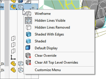
FIGURE 19.2 You can remove overrides in the assembly Display pane.
When you select Clear Override, SolidWorks clears any overrides for the currently selected component. Clear All Top Level Overrides clears all overrides in all the subassemblies in the entire top-level assembly. There is no intermediate option to clear all top-level overrides for a particular subassembly; if you want to distinguish between overrides at that level, you need to clear several individual overrides. The options to remove overrides do not affect top-level components.
The active display state appears in angle brackets after the configuration name and the filename at the top of the FeatureManager, as shown in the image on the left in Figure 19.3. Display states are created and managed in a panel at the bottom of the ConfigurationManager, as shown in the image on the right in Figure 19.3. To create a new display state, simply right-click in the Display pane and choose Add Display State. As an alternative, you can isolate the components you need to show and then click the Save icon on the Isolate tab to create a new display state.
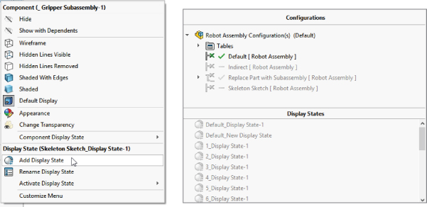
FIGURE 19.3 Display states shown in the FeatureManager and the ConfigurationManager
SolidWorks also allows you to open display states right from the Open dialog. This can be a big time-saver when you're opening very large assemblies that make good use of display states.
Using Display States with Drawings
Display states can be shown on drawings. If you only show or hide parts in display states, you can still use display states on drawings. For display states that change the display mode (Wireframe, Shaded, and so on) to work properly, you must set the view to the desired display mode and then select the display state from the PropertyManager for the view.
Using Part Display States in Parts
Parts can also have display states, including separate bodies within parts. You can control the part display state for specific instances of a part within an assembly in the Component Properties dialog box. Using part display states offers the same advantages as using assembly display states (mainly display speed), especially when compared to configurations.
Understanding Assembly Configurations
Assembly configurations are used for many different purposes, including assembly performance, simplified assemblies, variations of assemblies, assemblies in different positions or states, manufacturing assembly processes, and many others. Like part configurations, assembly configurations also have a few best-practice suggestions. Configuration settings for assemblies control how an assembly appears in a Bill of Materials (BOM), and what happens to parts, features, or mates that are added to other configurations, and so on. All these uses of assembly configurations are discussed in this section.
Applying Configurations for Performance
Assembly configurations are some of the best tools to make working with large assemblies easier. You can use several techniques to improve the speed of working with assemblies. Selecting a method that is appropriate to the situation is important because each method has its strengths and weaknesses.
SUPPRESSING COMPONENTS AND FEATURES
The most obvious use of configurations for improving assembly speed is to have a configuration or several configurations with suppressed components. Suppressed components are not loaded or displayed, so memory and video power are conserved.
Schemes that you may want to use for suppressing parts need to have one of the following:
- Configurations that isolate functional areas of an assembly
- Configurations that remove the fasteners or purchased components
- Configurations that remove complex parts
- Configurations that leave only the parts used in in-context relations
- Configurations that suppress patterns and assembly features
- Assembly configurations that use simplified part configurations
- Configurations that show the assembly in different positions
- Variations of the assembly using different part configurations
If you suppress the “ground” part or any part that connects groups of parts, keep in mind that this can cause other parts to float in space unattached. Obviously, this is not a good situation, and you should avoid it if possible. One way to avoid it is to use an assembly layout sketch and mate the parts to the sketch instead of to the ground part.
Aside from components, other items can also be suppressed to improve performance, such as assembly features and component patterns. Do you really need to see all those parts patterned around the assembly to work on it in a simplified representation? You may be able to suppress the parts. If you feel that you cannot suppress parts, then at least consider using display states to hide parts that are needed to complete the parametrics but do not need to display.
CONFIGURING SPEEDPAKS
A SpeedPak is a configuration that uses only display data for selected faces and bodies to represent an entire subassembly, instead of opening all the parts in the assembly. In fact, a SpeedPak stores the geometry in the assembly file so it doesn't have to open any part files at all. Further, it stores all the graphic data (graphics-triangles) for all components and the body data for the selected faces or bodies.
SpeedPaks are mentioned here because they are a form of configuration, essentially a derived configuration. As a result, you can have top-level assembly configurations that call on subassemblies to use their SpeedPaks. That can be extremely helpful with very large assembly and drawing performance.
USING PART CONFIGURATIONS FOR SPEED
Simplified part configurations can consist of configurations with cosmetic features such as small fillets and extruded text, or other cosmetic details that are suppressed. Assembly configurations can use different part configurations, which, for example, would enable you to make an assembly configuration called “Simplified” and in it reference all the “Simplified” part configurations.
Other special operations for assembly configurations in the Open dialog box include creating a new configuration that has all the components suppressed. This enables you to see the structure of the assembly without fully resolving all the components. Another option is to open the assembly with a new configuration, where all the components are resolved. Beyond that, the Open dialog box also enables you to select a specific configuration to open so that you don't have to wait for the last saved configuration to load and then make the change.
GETTING FAMILIAR WITH THE ADVANCED COMPONENT SELECTION
The Advanced Component Selection dialog box, shown in Figure 19.4, was formerly called Advanced Show/Hide Components. You can access this dialog box by right-clicking the configuration name in the ConfigurationManager and selecting Advance Select.
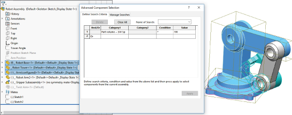
FIGURE 19.4 The Advanced Component Selection dialog box
This tool enables you to establish search criteria and show or hide parts based on the criteria. Multiple criteria can be used, stored, and retrieved. This tool is generally underused, and people are often surprised to find it in the software. The Category 1 options enable you to search on things such as document name, in-context status, part mass, and other standard SolidWorks information. Category 2 can be either custom property information or structured options for Category 1, such as specific in-context conditions.
LOOKING AT THE ISOLATE FUNCTION
Isolate works like the inverse of the Hide command. If you select multiple parts and click Isolate from the RMB menu, the selected parts remain shown, and everything else becomes hidden. A little pop-up menu gives you the option to show the removed components in a Wireframe or Transparent display mode, or to save the current display as a new display state. This is a very useful function, as shown in Figure 19.5.
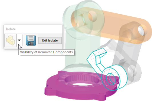
FIGURE 19.5 The Isolate function can create display states.
CONTROLLING DISPLAY PERFORMANCE
Overall, SolidWorks performance is split into two categories: CPU processing and GPU (graphics processing unit) processing. Which of these functions your computer performs better depends on your hardware, drivers, and system maintenance, among other factors.
When trying to speed up the performance of an assembly, you can make the biggest impact by reducing the load on both the CPU and the GPU. You can do this by suppressing a part. When a part is suppressed, it is neither calculated nor displayed; this means the load on each processor for that part is zero.
When you hide a part, its parametric features are still calculated by the CPU; however, because the part is hidden, it does not create a load on the GPU. If you have a good main processor and a questionable video card, then you will achieve a greater benefit from removing graphics load from your display. Simply unload the hidden component from RAM.
Using Lightweight Parts Settings
If you want to show a part, but not calculate any of its parametric relations, you can use lightweight parts. You can access the Lightweight default settings by choosing Tools ➢ Options on both the Assemblies and Performance pages. You can make parts lightweight through the RMB menu. The opposite of lightweight is resolved. Resolved means that the part is fully loaded, its parametrics are loaded and calculated by the CPU, and its graphics display data is calculated and shown by the GPU. In lightweight, the body data is loaded, along with the reference geometry features and the mates for the top-level components. The graphics data will always be computed in the current session in both Resolved and Lightweight modes. The LDR mode is the only mode where the graphics data is read from the file and not computed in the session.
Working with SpeedPak
There is some confusion about where the SpeedPak functionality falls in this scheme of things. With a SpeedPak, the parametrics are not loaded, but the graphics are. In addition, some of the geometry is selectable, as if it were imported geometry (actual geometry but without rebuildable parametrics). However, a SpeedPak applies only to subassemblies, where the need for improvement is much higher.
There is a five-way relationship among the Resolved, SpeedPak, Lightweight, Hidden, and Suppressed states, as shown in Figure 19.6.
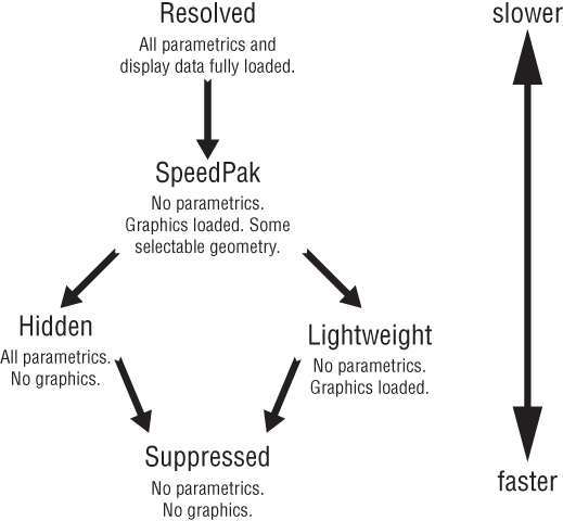
FIGURE 19.6 The relationship among the Resolved, SpeedPak, Lightweight, Hidden, and Suppressed states
Comparing Resolved to Unsuppressed
The terminology becomes a little convoluted here because of the relationships between the five different states. In parts, the feature states are easy to remember because features can be either suppressed or unsuppressed. However, in assemblies, there are five states instead of two, so unsuppressed could mean anything that is not suppressed, which still leaves three states. For this reason, resolved is used instead of unsuppressed when dealing with components in an assembly.
Using Configurations for Positions
When you use configurations to display an assembly in various positions, you can do it either by changing mates or by changing a layout sketch. Mates are configurable in two ways: Mates can be suppressed and unsuppressed, and angle and distance mate values can be configured in the same way that sketch dimensions can be configured. Although creating a mate scheme that enables you to reposition the assembly using mate suppression states and values is essential to this method, it may not be the best approach. When mates are suppressed, the components move, and if the mates are later unsuppressed, the assembly may not return to the original position. Mates can often be solved in different orientations and may flip if turned on and off in this way.
Using a skeleton or layout sketch to mate parts may be a better approach, although this also has drawbacks. If you mate to a layout sketch, you cannot use Dynamic Assembly Motion. If you use the mate scheme discussed previously, this generally means having a fully defined assembly, and this doesn't allow for Dynamic Assembly Motion.
As a compromise, a good way to handle this is by using one configuration for Dynamic Assembly Motion, with one or more open degrees of freedom. You can use other configurations to fully define the mechanism and show it in particular positions using either method. Probably the best way to demonstrate this idea is with an example using the robot arm assembly.
POSITIONING WITH MATES
First, look at positioning with mates. On an assembly such as this one, the goal is to position the grippers. You can do this a couple of ways, both directly and indirectly. In the assembly used for this chapter, the grippers have been rebuilt as a subassembly, which allows different types of control. Notice that the subassembly has a configuration for the closed position and one that allows Dynamic Assembly Motion. In addition, the subassembly is being solved as Flexible. Figure 19.7 shows the assembly and the FeatureManager.

FIGURE 19.7 The assembly used for this example
Driving the Position Directly
A sketch point has been added to the subassembly to identify the precise point on the gripper that is to be positioned. Sketch points have also been added to the main assembly to represent parts that need to be picked up by the robotic arm.
Check the derived configurations under the default configuration. Notice that when you switch between certain configurations, the parts seem to separate. Moving one of the links causes the parts to snap back together again. This is probably because there are so many options when moving between configurations that the software has difficulty choosing a final position. This is definitely one of the potential problems when using configured mates to show an assembly in various positions.
Notice also that although the grippers are positioned correctly, the arm is still allowed to swivel around the intended target point. You can correct this by defining an orientation for the grippers for each location. If an additional pivot were added to the assembly, then fully defining the parts would become more difficult. The arm would not be able to reach any additional points, but it would not be so limited in orienting the grippers at each point.
Driving the Position Indirectly
You can also use mates to drive configured positions of the assembly using a series of angle mates. This makes it more difficult because to get to a particular location, you have to do some calculations, but the angle mates are more stable than simply relying on moving parts to unconstrained positions.
If you cycle through the derived configurations under the Indirect top-level configuration, you will notice that mates are not suppressed and unsuppressed; instead, the values are changed. This makes it more difficult to position the grippers precisely, but because it is specific about the positions of the individual parts, there is no ambiguity.
POSITIONING WITH SKETCHES
Although this technique still uses mates to position the parts and to change the position, you change sketch dimensions rather than mate values. Sketches used to drive parts from an assembly are sometimes called layout sketches or skeletons. They are also discussed in Chapter 16, “Working with Assembly Sketches and Layouts,” for in-context or top-down assembly techniques. Figure 19.8 shows the assembly that is used for the rest of this chapter.
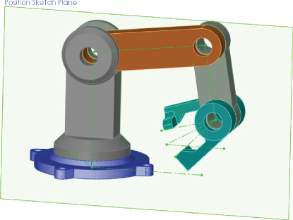
FIGURE 19.8 Positioning assembly components with sketches
This particular assembly is driven by two sketches on different planes to govern the position of the parts. Keep in mind that this assembly has been used for all the other techniques as well; this means that all these techniques can exist together simultaneously and are controlled by configurations.
Examine the assembly to see how the parts are mated to the sketches. This is important. The first time you create a part such as this, you may be tempted to mate part planes to the sketch lines.
Applying Configurations for Product Variations
In this case, product variations are variations in size or part replacement. Some examples are a 4-foot cabinet and an 8-foot cabinet, or a two-button mouse and a three-button mouse.
As a simple example, Figure 19.9 shows the familiar robotic arm assembly, but with a variation: one of the arms has been replaced with a subassembly. The subassembly is made of the original replaced part using configurations, and there are configurations of the subassembly, which is again being used as a flexible subassembly.

FIGURE 19.9 A part that is replaced by a subassembly
Through the course of this chapter, the robot arm assembly has greatly increased in complexity, but it has retained the original information that was in the first version. Maintaining valid assembly data through manually managed configurations is difficult, and all it takes is a simple mistake to wipe out lots of assembly configuration data. Appropriately, the next section discusses assembly design tables.
Using Design Tables for Assembly Configurations
This chapter augments information that you need to know to use design tables effectively in assemblies. Assembly design tables can do everything that part design tables can do, except for selecting configurations of base parts and split parts, which are not valid assembly functions. Assembly design tables can also do some things that a part design table cannot, including the following:
- Suppressing the state of a part (R for Resolved or S for Suppressed)
- Assigning the component configuration for the assembly configuration
- Enabling you to activate the Never Expand In BOM option
Figure 19.10 shows the design table results from auto-creation using the robot arm assembly. Some columns have been hidden to make it small enough to fit on the page. If you want to see the entire table, you must open the assembly. If you edit the design table, you will probably want to use the Open In Separate Window option, which is easier to navigate and control.
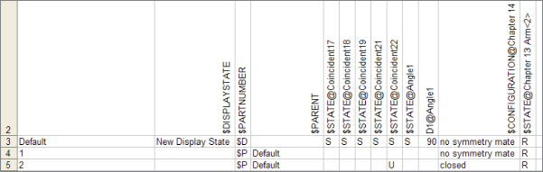
FIGURE 19.10 A design table automatically created from the robot arm assembly
Working with Modify Configurations and the Configuration Publisher
The Modify Configuration interface is a dialog box where you can create configurations to configure dimensions, features, and custom properties in parts; you can use it in assemblies as well. It is sometimes used in place of design tables when you do not need the advanced functionality of Excel.
The Configuration Publisher is used to create a PropertyManager that pops up when the part is placed into an assembly. The PropertyManager enables you to select a configuration to go into the assembly. You can also create new configurations on demand, inside the constraints defined in the Configuration Publisher. It is a great tool for assemblies with zillions of possible variations (for example, the catalog of a crane vendor). The Configuration Publisher is also available in assemblies; this means you can use a pop-up PropertyManager when assemblies are placed into other assemblies as well. Library subassemblies may be less common than library parts, where the pop-up PropertyManager would be used to best effect.
Both tools are useful for managing assembly configurations. Design tables offer the most complete control, but they also have some drawbacks associated with being tied to Microsoft Excel. Both Modify Configurations and the Configuration Publisher are internal to SolidWorks, regardless of the level of the software you have purchased, so if you use one of them, you can be sure that whomever you send data to can access all the functionality.
Looking at Assembly Configuration Dos and Don'ts
Assembly configurations have some potential pitfalls that you can avoid if you pay attention to some of these dos and don'ts.
- Avoid using Delete as an editing option when working with configurations. Delete is forever and removes items from all configurations.
- Avoid the use of in-context relations to size parts when you are also using configurations to size parts. A nonconfigured part driven by a configured part only causes confusion.
- Avoid using configurations to represent document control-type revisions. When people attempt to do this, it ultimately limits the kinds of edits they can make to their parts and assemblies, and it is far too easy to make a mistake that wipes out all their work. In the end, this is not a viable technique.
- If you are working with manually created configurations, you should create a new configuration and activate it before making the changes. Otherwise, you will end up trying to set the original configuration back to the way it was.
- Remember to select the This Configuration Only option for changed dimensions instead of leaving it at the default All Configurations setting.
Tutorial: Working with Assembly Configurations
To begin this tutorial, open the assembly named Chapter 19 -Bike start tutorial.sldasm. This file contains all the aspects that you need to work with in this chapter, including subassemblies, motion configurations, and part configurations.
To learn how to work with assembly configurations, follow these steps:
- Prepare to use configurations by splitting the FeatureManager window into upper and lower panes. Place the FeatureManager on the top and the ConfigurationManager on the bottom.
- Before starting to make changes to this assembly, add the top-level configurations that you will need, as follows:
- Small Tires
- Motion Configuration
- Skeleton Driven Positions
- Mate Driven Positions
- Make sure the Advanced options for each configuration are set to suppress new features and mates and suppress new components.
- Activate the Small Tires configuration. Figure 19.11 shows the FeatureManager up to this point.
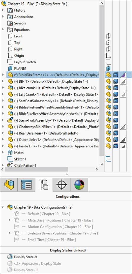
FIGURE 19.11 The FeatureManager and ConfigurationManager up to step 4
- Open the Front Wheel Assembly in its own window, and switch to the ConfigurationManager. Add a configuration called Small Tires, and change the tire to the configuration called Small Tires, which has already been created.
- Switch back to the main assembly window (Ctrl+Tab), right-click the Front Wheel Assembly in the FeatureManager, and select Component Properties. Select the Small Tires configuration for the Front Wheel assembly, as shown in Figure 19.12.
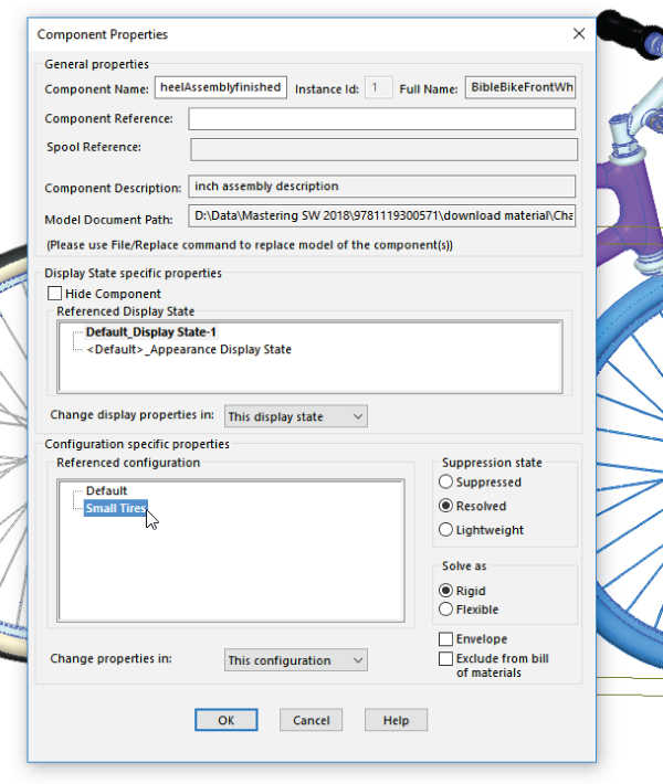
FIGURE 19.12 Changing the tires in the Component Properties dialog box
- Repeat steps 4 through 6 for the Rear Wheel assembly.
- Double-click another configuration from the list, and watch the assembly change from small to fat tires.
- Change to the Motion configuration. Right-click the Stem-Fork assembly, select Component Properties, and set the assembly to be solved as Flexible.
- Exit the dialog box, and check to see that the fork linkage mechanism moves by dragging the fork. Notice that the fork works but the front wheel does not move with it. The bike design is not yet complete, so you do not need to worry about that at this point. Putting the front wheel in the fork assembly could be used to make the wheel move with the fork.
- Switch to the Skeleton Driven Positions configuration.
- Display the assembly layout sketch at the top of the FeatureManager.
- Create two new derived configurations under the Skeleton Driven Positions configuration, one called Default Position and the other called Compressed Position.
- Activate the Default Position configuration, and make a coincident mate between the Top plane of the Chainstay part and the sketch line indicated in Figure 19.13. Again, the wheel does not move at this time.
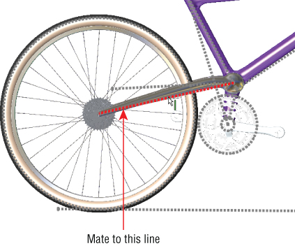
FIGURE 19.13 Positioning the rear of the bike
- Activate the Compressed Position configuration, and make a coincident mate between the same plane and the line that is angled up at 10 degrees.
- Switch to the Mate Driven Position configuration. Change the stem-fork assembly to a flexible subassembly (right-click and choose Component Properties ➢ Solve As Flexible).
- Add new derived configurations called 1, 2, and 3. While creating the new configurations, ensure that the Suppress New Features And Mates and the Suppress New Components options are selected. Leave the 1 configuration activated.
- Make an angle mate between the Bike assembly Top plane and the face of the link, as shown in Figure 19.14.
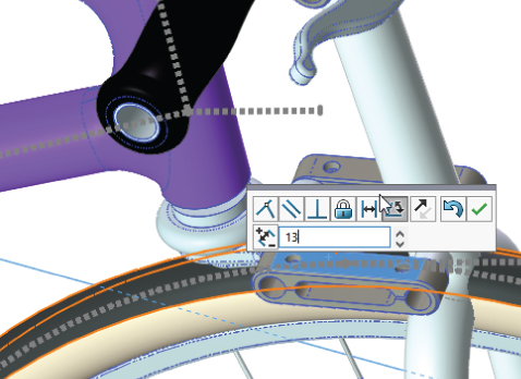
FIGURE 19.14 Using angles to position the fork
- After the mate is complete, double-click the angle dimension (you may have to double-click the angle mate to get it to display and then zoom out to see it), and change the value to 18 degrees. Again, with the change, the fork may fly to an unexpected location. Pressing Ctrl+Q brings it back.
- Switch to the configuration 2, unsuppress the angle mate that you made in step 18 and change the value to 25 degrees. You may have to change the configuration 2 to Flexible, although it should inherit this property from the parent configuration.
The Bottom Line
Display states in the assembly can save you lots of time because they change faster than configurations and offer more options for visualization, including mixed display modes. Assembly design tables can select display states and drive many other parameters in assemblies. Remember also that Modify Configurations and the Configuration Publisher work in assemblies as well as in parts. Assembly configurations are very powerful tools for product variations and performance, especially when combined with a SpeedPak.
- Master It List at least three of the reasons or conditions under which to use display states instead of configurations.
- Master It List at least three reasons to use design tables when you're working with assembly configurations.
- Master It Explain the difference between Hidden and Lightweight model states.