
Chapter 3
Working with Sketches and Reference Geometry
The first step to learning how to create models in SolidWorks is to learn how to sketch. If you are coming from another history-based modeling program, many of your skills are transferable to SolidWorks. If you have never used CAD before, think of the sketch-feature relationship as creating a simplified 2D drawing that represents a portion of the part that you can make with some sort of process such as extruding or revolving.
So far in this book, you have looked mainly at concepts, settings, and setup, which are necessary but mundane. In this chapter, you'll begin to learn how to control parametric relationships in sketches. Then in later chapters, you'll begin to build models—simple at first, but gaining in complexity and always demonstrating new techniques and features that build your modeling vocabulary. Beyond this, you'll use the parts to create assemblies and drawings.
This chapter deals entirely with sketches in parts. However, you can apply many of the topics covered here to sketches in assemblies and drawings. Some related topics, such as layout sketches, have functionality that is exclusive to assemblies, and these topics will be covered in later chapters.
Creating a New Part
Before you can create a sketch, you must create a new part. To create a new part, you must follow these two simple steps:
- Click the New tool.
- Select a part template from the list. The part template will have the units and drafting standards already set.
Each new part will start with some basic items. The items you need to focus on about right now are the base planes and the origin (shown in Figure 3.1 in the FeatureManager of a brand new blank part made from a template). The planes can be named anything you want: X, Y, and Z; Front, Top, and Right; Larry, Moe, and Curly; or whatever. The naming scheme is determined by the person who saved the template.

FIGURE 3.1 The FeatureManager of a new part
Chapter 1, “Introducing SolidWorks,” has more detailed information on part templates and setting up SolidWorks to use existing templates. Several templates are included with the downloadable materials for this book.
Creating a Sketch
Best practice for sketching in SolidWorks dictates that you should keep a few things in mind while creating and editing sketches:
- Sketches need to be clean and precise, with no gaps or overlaps and no stray sketch entities.
- It is best to keep each sketch simple. Complex sketches tend to fail or cause problems later.
- You should create sketches with the general “design intent” (for example, a horizontal rectangle) and then add the details later (for example, precise dimensions).
- It is best if you can pick up the desired automatic relationships as you sketch rather than waiting to create them manually later. At the same time, you need to be able to avoid extraneous and unwanted automatic relationships you may get from careless sketching.
- The use of reference geometry can save you from unwanted parent/child relationships between features.
SolidWorks allows several workflows you can use to create a sketch. To try to simplify it, think of it this way. You have the Sketch tool that opens a sketch, and you have tools such as Line, Arc, Circle, and so on. You also have planes and planar faces, straight line segments, and straight edges. To create a new sketch, you have to make two selections. One selection must be a tool that tells SolidWorks you want to make a sketch, such as the Sketch tool, or Line, Arc, Circle, etc. The second selection has to be where you want the sketch to be located, such as a plane, a planar face, or an edge on which a perpendicular plane will be created.
Here's one way to create a new sketch:
 Click the Sketch tool. Notice the prompts in the FeatureManager area.
 Click the Front plane in the FeatureManager.
Here's another way:
 Right-click on a plane (either in the FeatureManager or in the graphics window if they are shown). As an alternative, you can click a plane to call the context-sensitive toolbar.
- Select Sketch from the context bar (on top of the RMB menu).
Here is yet another way:
- Click the Line tool. Notice the FeatureManager disappears and the PropertyManager shows up in its place. The flyout FeatureManager has actually moved over into the graphics window and has collapsed.
 Click the down arrow next to the Part1 symbol.
- Click a plane in the tree. Clicking a straight edge creates a plane perpendicular to the end of the edge closest to where you clicked. The plane will show up in the FeatureManager automatically. (This is an obscure trick that a lot of existing users have forgotten.)
When you create a sketch, several tools become available, specifically all the sketch entities and tools. Open sketches and selection filters are two very common sources of frustration for new users. If you are having difficulty selecting items that you want because the software won't allow you to select specific items or because items are grayed out, you could have an open sketch. Several indicators will let you know when you are in Sketch mode:
- The title bar of the SolidWorks window displays the text “Sketch X of Part Y.”
- The lower-right corner of the status bar displays the text “Editing Sketch X.”
- The Confirmation Corner displays a Sketch icon in the upper-right corner of the graphics window.
- The Sketch toolbar button displays the text “Exit Sketch.”
- The red sketch origin is displayed.
- If you are using the grid, is displayed only in Sketch mode.
While most users find the sketch grid annoying or distracting, some new users use it as a reminder that they are in Sketch mode. If you tend to forget or would like a visual cue, the sketch grid is a useful option. You can find the settings for displaying the grid in Sketch mode at Tools ➢ Options ➢ Document Properties ➢ Grid/Snap.
A sketch can be edited only when it is open (unless Instant 3D is off—I recommend you turn it off, except when you intend to use it). You can have only one sketch open at a time. SolidWorks uses many indicators to show the state of a sketch, including the Confirmation Corner and the taskbar.
Just as you can create sketches in several ways, you can also open existing sketches several ways:
- Right-click a sketch in the FeatureManager or graphics window and select Sketch.
- Select a sketch from the FeatureManager or graphics window, and click the Sketch icon on the Sketch toolbar.
- Left-click a sketch or feature and click the Sketch icon from the context toolbar.
 Double-click a sketch with the Instant 3D tool active.
Identifying Sketch Entities
SolidWorks sketching tools include many types of entities. Some you will use all the time, and others you may never use, even if you spend years working with the software. In this section, I offer tips for using each entity.
Using the Sketch Toolbar
In the following section, I first identify the default buttons on the Sketch toolbar, followed by the rest of the entities that you can access by choosing Tools ➢ Customize ➢ Commands ➢ Sketch.
Take a minute and hover your cursor over the buttons on the Sketch toolbar. Let the tooltips come up. When a button has a triangle to the right of it, the triangle is a flyout button that provides access to additional tools. For example the Line flyout allows you to also select the centerline (also used as construction line) and the midpoint line. As shown in Figure 3.2.
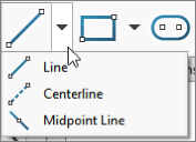
FIGURE 3.2 Options with the Line flyout toolbar
![]() The Sketch tool opens and closes sketches. You may notice that the name of the button changes depending on whether the sketch is open or closed. If you preselect a plane or planar face and then click the Sketch button, SolidWorks opens a new sketch on the plane or face. If you preselect a sketch before clicking the Sketch button, SolidWorks opens this sketch. If you preselect an edge or curve feature before clicking the Sketch button, SolidWorks automatically makes a plane perpendicular to the nearest end of the curve. If you do not use preselection and click the Sketch tool with nothing selected, SolidWorks prompts you to select a plane or planar face on which you want to put a new sketch, or an existing sketch to edit.
The Sketch tool opens and closes sketches. You may notice that the name of the button changes depending on whether the sketch is open or closed. If you preselect a plane or planar face and then click the Sketch button, SolidWorks opens a new sketch on the plane or face. If you preselect a sketch before clicking the Sketch button, SolidWorks opens this sketch. If you preselect an edge or curve feature before clicking the Sketch button, SolidWorks automatically makes a plane perpendicular to the nearest end of the curve. If you do not use preselection and click the Sketch tool with nothing selected, SolidWorks prompts you to select a plane or planar face on which you want to put a new sketch, or an existing sketch to edit.
![]() The 3D Sketch tool opens and closes 3D sketches with no preselection required. 3D Sketch is covered in more detail in Chapter 6, “Getting More from Your Sketches.”
The 3D Sketch tool opens and closes 3D sketches with no preselection required. 3D Sketch is covered in more detail in Chapter 6, “Getting More from Your Sketches.”
![]() The Smart Dimension tool can create all types of dimensions used in SolidWorks, such as horizontal, vertical, aligned, radial, diameter, angle, and arc length. You can create dimensions several ways, as shown in Figure 3.3. The dimensions shown were created by selecting the line itself and moving the cursor to different locations to get horizontal, vertical, or aligned dimensions
The Smart Dimension tool can create all types of dimensions used in SolidWorks, such as horizontal, vertical, aligned, radial, diameter, angle, and arc length. You can create dimensions several ways, as shown in Figure 3.3. The dimensions shown were created by selecting the line itself and moving the cursor to different locations to get horizontal, vertical, or aligned dimensions

FIGURE 3.3 The Insert Line PropertyManager interface
We will return to smart dimensions later in this chapter.
![]() The Line tool creates straight lines using one of two methods. You should practice these two methods to determine which one you prefer. If you have used other CAD products, you probably already have a preference.
The Line tool creates straight lines using one of two methods. You should practice these two methods to determine which one you prefer. If you have used other CAD products, you probably already have a preference.
- Click+click: This method is used for drawing multiple connected end-to-end lines. Click and release the left mouse button to start the line; each click and release ends the previous line and starts a new one. Double-click (to cancel the first click point but remain in the Line command), press Esc (to exit the Line command altogether), or deselect the Line tool to end.
- Click-and-drag: This method is used to draw individual or unconnected lines. Click, drag, and drop. The first click initiates the line, and the drop ends it.
Alternative methods exist for drawing lines that include horizontal, vertical, angle, and infinite lines. The interface for these options appears in the PropertyManager, as shown in Figure 3.3.
- Horizontal, Vertical: These settings require you to select a starting point and an ending vertical or horizontal position. I see no compelling reason to use this setting instead of the regular Line command. It is useful in a strictly 2D world, but I can't see what I would use it for here.
- Angle: This setting enables you to specify an angle and drag a line at this angle. Again, I can find no compelling reason to use this tool.
- Infinite Length: SolidWorks parts have a working space limited to 1000 meters on a side, centered on the origin. Infinite lines extend well beyond this, although you cannot draw or dimension a regular line outside of this box. This feature would be most useful if you are working with parts with vastly divergent scales of features (some very large, some very small).
![]() When you select the Corner Rectangle tool, you can create a rectangle by clicking one corner and dragging to the diagonal corner. This action creates four lines with Horizontal and Vertical sketch relations, as appropriate. The Corner Rectangle is also available as a flyout icon with a Corner Rectangle, Center Rectangle, 3 Point Corner Rectangle (rectangle at an angle), 3 Point Center Rectangle, and Parallelogram. Figure 3.4 shows the flyout and flyout icons, as well as the PropertyManager for the Rectangle, which also enables you to switch types of rectangles easily. Remember that the shortcut shown on the right cycles through all of the rectangle options in the PropertyManager.
When you select the Corner Rectangle tool, you can create a rectangle by clicking one corner and dragging to the diagonal corner. This action creates four lines with Horizontal and Vertical sketch relations, as appropriate. The Corner Rectangle is also available as a flyout icon with a Corner Rectangle, Center Rectangle, 3 Point Corner Rectangle (rectangle at an angle), 3 Point Center Rectangle, and Parallelogram. Figure 3.4 shows the flyout and flyout icons, as well as the PropertyManager for the Rectangle, which also enables you to switch types of rectangles easily. Remember that the shortcut shown on the right cycles through all of the rectangle options in the PropertyManager.
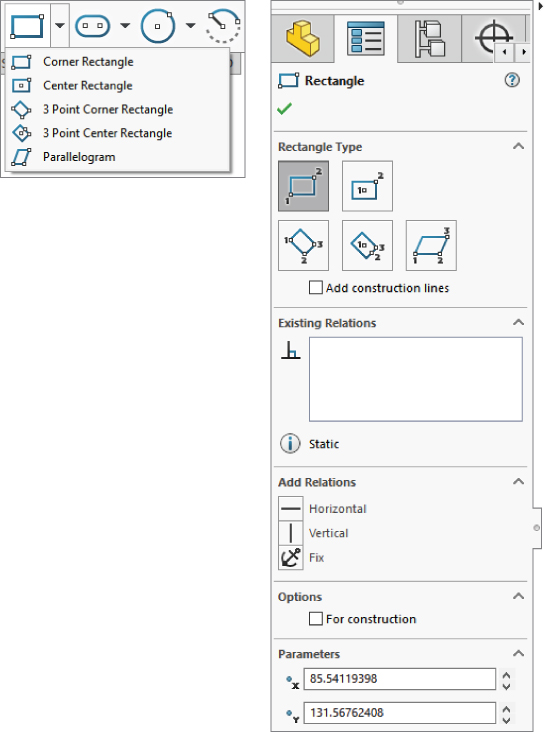
FIGURE 3.4 The Rectangle flyout with associated icons
If you have activated any of the items under the Rectangle flyout, you can press the A key to cycle through the rest of the items. If you have already started sketching the rectangle but haven't yet finished, pressing the A key will cancel out of the current rectangle and cycle to the next type. This may be faster than actually using the flyout; just click the first icon and cycle to the one you want. The cursor icon changes to show which type of rectangle it will presently sketch.
Notice the Add Dimensions check box in the PropertyManager. Selecting this box while creating a rectangle causes the software to add dimensions aligned with the sides of the rectangle. This option is also available for lines, arcs, and circles.
Note that if you use this option in conjunction with the Enable On-Screen Numeric Input On Entity Creation setting, found at Tools ➢ Options ➢ Sketch, it makes creating sketch entities to the correct size immediately much easier.
![]() The Parallelogram tool is used to draw a parallelogram (adjacent sides are not perpendicular, and opposite sides are parallel). Click one corner of the parallelogram, and then click the second and third corners. It works like the 3 Point Rectangle except that adjacent sides are not perpendicular.
The Parallelogram tool is used to draw a parallelogram (adjacent sides are not perpendicular, and opposite sides are parallel). Click one corner of the parallelogram, and then click the second and third corners. It works like the 3 Point Rectangle except that adjacent sides are not perpendicular.
![]() The Circle tool creates a circle using one of two methods, which are available from either the flyout icon or the Circle PropertyManager:
The Circle tool creates a circle using one of two methods, which are available from either the flyout icon or the Circle PropertyManager:
- Center Creation: Click the center of the circle and drag the radius. The Circle PropertyManager calls this function center creation.
- Perimeter Creation: To create a circle using this technique, you must select the Perimeter Creation option from the Circle PropertyManager window after clicking the Circle tool. There is also a separate Perimeter Creation toolbar button and a menu selection for Tools ➢ Sketch Entities ➢ Perimeter Circle. This creates only tangent relations with other entities in the current sketch; if you are building a circle from model edges or entities in other sketches, you need to apply the relations manually. SolidWorks calls these functions perimeter creation.
- Tangent to Two Entities: Start the circle with the cursor near one line in the sketch. A Tangent symbol appears by the cursor with a yellow background. Click and drag the diameter to the second tangent entity, where a similar cursor symbol should appear. Release the mouse button and right-click the green checkmark icon. This process is shown in Figure 3.5.
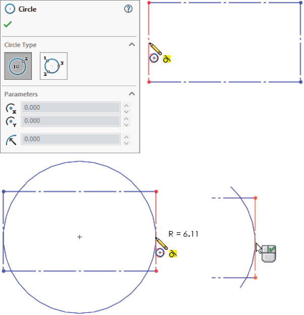
FIGURE 3.5 Creating a circle
- Tangent to Three Entities: Use the same process used for Tangent to Two Entities, but omit the right-click of the green checkmark icon. After dropping on the second tangent, drag again to the third tangent entity.
- Tangent to Two Entities: Start the circle with the cursor near one line in the sketch. A Tangent symbol appears by the cursor with a yellow background. Click and drag the diameter to the second tangent entity, where a similar cursor symbol should appear. Release the mouse button and right-click the green checkmark icon. This process is shown in Figure 3.5.
![]() When you select the Centerpoint Arc tool, you can create arc by clicking the center, dragging the radius, and then clicking and dragging the included angle of the arc. The first two steps are exactly like those for the Center-Radius circle.
When you select the Centerpoint Arc tool, you can create arc by clicking the center, dragging the radius, and then clicking and dragging the included angle of the arc. The first two steps are exactly like those for the Center-Radius circle.
![]() The Tangent Arc tool creates an arc tangent to an existing sketch entity. Depending on how you move the cursor away from the end of the existing sketch entity, the arc can be tangent, reverse tangent, or perpendicular, as shown in Figure 3.6.
The Tangent Arc tool creates an arc tangent to an existing sketch entity. Depending on how you move the cursor away from the end of the existing sketch entity, the arc can be tangent, reverse tangent, or perpendicular, as shown in Figure 3.6.
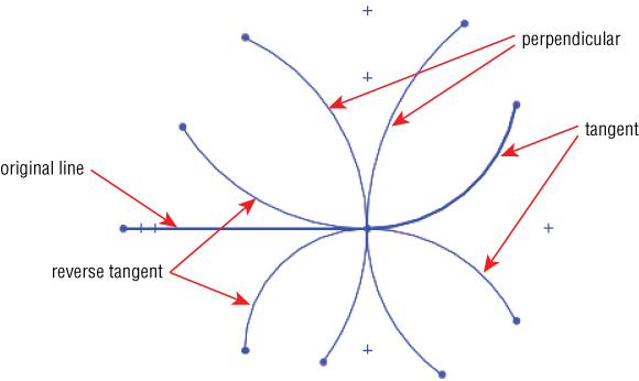
FIGURE 3.6 Using the Tangent Arc feature
Another way to create a tangent arc (called auto-transitioning) is to start drawing a line from the end of another sketch entity, and while holding down the left mouse button, press the A key; or return the cursor to the starting point and drag it out again. This second method can be difficult to master, but it saves time compared to any of the techniques for switching sketch tools.
![]() The 3 Point Arc tool creates an arc by first establishing endpoints and then establishing the included arc, as shown in Figure 3.7. Again, this tool also works using the Click+click or click-and-drag methods.
The 3 Point Arc tool creates an arc by first establishing endpoints and then establishing the included arc, as shown in Figure 3.7. Again, this tool also works using the Click+click or click-and-drag methods.
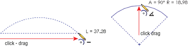
FIGURE 3.7 Creating a three-point arc
![]() The Sketch Fillet tool creates a sketch fillet in two ways. Either you can select the endpoint where the sketch entities intersect, or you can select the lines themselves, selecting the portion that you want to keep. Figure 3.8 illustrates both techniques.
The Sketch Fillet tool creates a sketch fillet in two ways. Either you can select the endpoint where the sketch entities intersect, or you can select the lines themselves, selecting the portion that you want to keep. Figure 3.8 illustrates both techniques.
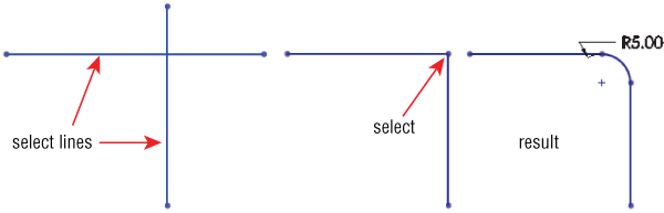
FIGURE 3.8 Creating a sketch fillet
![]() The Sketch Chamfer tool is on the same flyout as the Sketch Fillet by default. Sketch Chamfer does not have a list selection box the way that fillet does, and it does not use a preview like the fillet.
The Sketch Chamfer tool is on the same flyout as the Sketch Fillet by default. Sketch Chamfer does not have a list selection box the way that fillet does, and it does not use a preview like the fillet.
![]() The Centerline tool follows the same methods as regular lines and is called a construction line in some cases. Other construction entities, such as construction circles, are not available directly, but you can create them by selecting the For Construction option in the PropertyManager for any entity.
The Centerline tool follows the same methods as regular lines and is called a construction line in some cases. Other construction entities, such as construction circles, are not available directly, but you can create them by selecting the For Construction option in the PropertyManager for any entity.
![]() The Spline tool draws a freeform curve. Splines may form either a single closed loop or an open loop. In either case, the spline is not allowed to cross itself. You can draw a spline by clicking each location where you want to add a control point. Figure 3.9 identifies the elements of a spline. The detail image shows the structure of a spline handle.
The Spline tool draws a freeform curve. Splines may form either a single closed loop or an open loop. In either case, the spline is not allowed to cross itself. You can draw a spline by clicking each location where you want to add a control point. Figure 3.9 identifies the elements of a spline. The detail image shows the structure of a spline handle.

FIGURE 3.9 The structure of a spline and spline handles
Splines are used mainly for freeform complex shapes in 2D and 3D sketches, although you can also use them for anything in which you would use other sketch elements. If you need more information on splines and complex shape modeling, refer to the SolidWorks Surfacing and Complex Shape Modeling Bible (Wiley, 2008).
![]() The Point tool creates a sketch point. Aside from limited cases of lofting to a point or using a point as a constraint sketch in a Fill feature, sketch points are usually used for reference, in patterns, or for the location of the centerpoint of Hole Wizard features.
The Point tool creates a sketch point. Aside from limited cases of lofting to a point or using a point as a constraint sketch in a Fill feature, sketch points are usually used for reference, in patterns, or for the location of the centerpoint of Hole Wizard features.
You can also use the sketch point as a virtual sharp. If two sketch entities do not actually intersect because of a fillet or chamfer, selecting the two entities and clicking the Point tool creates a point at the location where they would intersect if they were extended. This is useful for dimensioning to the sharp. Virtual sharp display is controlled by a Document Property setting.
![]() The 3D Sketch Plane tool creates a plane in a 3D sketch. I discuss 3D sketches in more detail in Chapter 6. By sketching on planes within a 3D sketch, you get most of the benefits and usage of 2D sketches, and you do not have to deal with history between sketches. Before committing too much work to this course, you should look into some of the shortcomings of 3D planes. The planes are treated just like any other entity in the 3D sketch, which means you can assign sketch relations to them, but it also means that they can move around within the sketch the way sketch entities do.
The 3D Sketch Plane tool creates a plane in a 3D sketch. I discuss 3D sketches in more detail in Chapter 6. By sketching on planes within a 3D sketch, you get most of the benefits and usage of 2D sketches, and you do not have to deal with history between sketches. Before committing too much work to this course, you should look into some of the shortcomings of 3D planes. The planes are treated just like any other entity in the 3D sketch, which means you can assign sketch relations to them, but it also means that they can move around within the sketch the way sketch entities do.
![]() The Add Relation tool displays a PropertyManager window that enables you to apply sketch relations. This interface appears to be obsolete, because it is easier to simply select sketch items and apply relations via the context toolbar or in the PropertyManager window that appears automatically when you select them; however, there are some subtle workflow-related reasons for using this tool.
The Add Relation tool displays a PropertyManager window that enables you to apply sketch relations. This interface appears to be obsolete, because it is easier to simply select sketch items and apply relations via the context toolbar or in the PropertyManager window that appears automatically when you select them; however, there are some subtle workflow-related reasons for using this tool.
Using the Add Relations dialog box has two advantages over simply selecting sketch entities and adding relations. When the Add Relation PropertyManager is active, you do not need to use the Ctrl key to select multiple entities. You also do not need to clear a selection before making a new selection for the next relation. These two reasons sound minor, but if you have a large number of sketch relations to apply, the workflow goes much more smoothly using this tool than the default method.
![]() The Display/Delete Relations tool enables you to look through the relations in a sketch and sort them according to several categories. From this window, you can delete or suppress relations and replace entities in relations.
The Display/Delete Relations tool enables you to look through the relations in a sketch and sort them according to several categories. From this window, you can delete or suppress relations and replace entities in relations.
![]() The Quick Snaps flyout enables you to quickly filter types of entities that sketch elements will snap to when you move or create them. To access the tools, click the drop-down arrow to the right of the toolbar button.
The Quick Snaps flyout enables you to quickly filter types of entities that sketch elements will snap to when you move or create them. To access the tools, click the drop-down arrow to the right of the toolbar button.
![]() The Mirror Entities tool mirrors selected sketch entities about a single selected centerline and applies a Symmetric sketch relation. In addition, a Dynamic Mirror function is described later in this chapter.
The Mirror Entities tool mirrors selected sketch entities about a single selected centerline and applies a Symmetric sketch relation. In addition, a Dynamic Mirror function is described later in this chapter.
![]() The Convert Entities tool converts edges, curves, and sketch elements from other sketches into entities in the current sketch. When edges are not parallel to the sketch plane, the Convert Entities feature projects them into the sketch plane. Some elements may be impossible to convert—for example, a helix, which would produce a projection that overlaps itself. Sketch entities created using Convert Entities get an On-Edge sketch relation.
The Convert Entities tool converts edges, curves, and sketch elements from other sketches into entities in the current sketch. When edges are not parallel to the sketch plane, the Convert Entities feature projects them into the sketch plane. Some elements may be impossible to convert—for example, a helix, which would produce a projection that overlaps itself. Sketch entities created using Convert Entities get an On-Edge sketch relation.
![]() The Offset Entities command works like the Convert Entities feature, except that it offsets the sketch to one side or the other of the projection of the original edge, sketch, or curve, and Offset Entities doesn't have a selection box. Figure 3.10 shows the PropertyManager interface for this command.
The Offset Entities command works like the Convert Entities feature, except that it offsets the sketch to one side or the other of the projection of the original edge, sketch, or curve, and Offset Entities doesn't have a selection box. Figure 3.10 shows the PropertyManager interface for this command.

FIGURE 3.10 The Offset Entities interface
The options available in the Offset Entities interface are as follows:
- Add Dimensions: This option constrains offset sketch entities. Instead of the On-Edge relations, Offset Entities creates an Offset sketch relation that cannot be re-created manually.
- Reverse: This option changes the direction of the offset.
- Select Chain: This option selects continuous end-to-end sketch entities.
- Bi-directional: This option offsets to both sides simultaneously.
- Cap Ends: This is available only when you have selected the Bi-directional option. Capping the ends with arcs is an easy way to create a slot from a sketch of the centerline. This function works with all sketch entities; it is not limited to straight slots. Figure 3.11 shows examples of the Cap ends option.
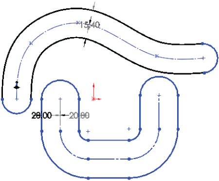
FIGURE 3.11 The Offset Entities interface
- Construction Geometry: This option enables you to select which geometry (if any) you would like to make into construction geometry—the original selection, or the entities that are offset.
In addition to the bidirectional offset with capped ends, SolidWorks also has slot sketch entities for straight and curved slots, which are covered later in this chapter. Composite slots (made of a combination of straight and curved sections) still require the offset method.
![]() The Trim tool is actually several functions rolled into one, including extending and deleting sketch entities. Figure 3.12 shows the PropertyManager interface for this function.
The Trim tool is actually several functions rolled into one, including extending and deleting sketch entities. Figure 3.12 shows the PropertyManager interface for this function.

FIGURE 3.12 The Trim interface
- Power Trim: This trims by dragging a cursor trail over multiple entities. The entities that you drag the cursor over are trimmed back to (or extend up to, when using the Shift key) the next intersecting sketch entity. Each time you trim an entity, a red box remains until you trim the next entity. If you backtrack with the cursor and touch the red box, this trim is undone. This option is best used when you need to trim a large number of entities that are easy to hit with a moving cursor. Figure 3.13 shows the Power Trim feature in action. You can also use Power Trim to extend sketch entities along their paths by dragging the endpoints. Regular dragging can also change the position or orientation of the rest of the entity, but by using the Power Trim feature, you affect only the length.
FIGURE 3.13 Power Trim in action
- Corner: This trims or extends two selected entities to their next intersection. When you use the Corner option to trim, the selected portion of the sketch entities is kept, and anything on the other side of the corner is discarded. Figure 3.14 shows two ways that the Corner option can work.

FIGURE 3.14 Using the Corner option
- Trim Away Inside: This trims away selected entities inside a selected boundary. The boundary may consist of a pair of sketch entities or a model face (edges of the face are used as the boundary). Only entities that cross both selected boundaries (or cross the closed loop of the face boundary twice) can be trimmed. This option does not trim a closed loop such as a circle, an ellipse, or a closed spline.
- Trim Away Outside: This functions exactly like the Trim Away Inside option, except that sketch entities outside of the boundary are discarded. The Trim Away Inside and Trim Away Outside options are illustrated in Figure 3.15.
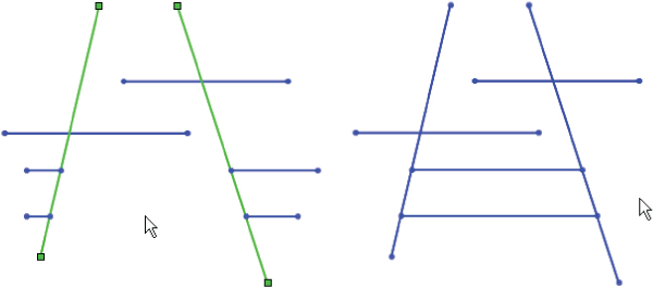
FIGURE 3.15 Using the Trim Away Inside and Trim Away Outside options
- Trim To Closest: This is the default setting. Clicking a sketch entity:
- Trims it back to the next entity if there is only one crossing entity.
- Trims between two crossing entities if there is more than one.
- Deletes the entity if there are no crossing entities.
- In all cases, the selected section of the entity is removed. The Trim To Closest option can also extend when you drag one entity to another; if an intersection is possible, the first entity is extended to the second entity. Figure 3.16 illustrates how the Trim To Closest option functions.
FIGURE 3.16 Using Trim To Closest to extend
![]() The Construction Geometry tool toggles between regular sketch entities and construction entities. Construction sketch entities are not used to create solid or surface faces directly; they are used only for reference—for example, revolve centerlines, extrude and pattern directions, and so forth. Be careful with the icon for this function, because it looks almost identical to the No Solve Move icon, especially as printed here in grayscale.
The Construction Geometry tool toggles between regular sketch entities and construction entities. Construction sketch entities are not used to create solid or surface faces directly; they are used only for reference—for example, revolve centerlines, extrude and pattern directions, and so forth. Be careful with the icon for this function, because it looks almost identical to the No Solve Move icon, especially as printed here in grayscale.
![]() The Stretch sketch tool is intended for use in sketches where there are enough dimensions to make a particular change difficult by changing dimensions only. Stretch enables you to specify a change that will change several dimensions simultaneously. Figure 3.17 shows the sketch being stretched. Notice one of the lines is not selected at the top, so the top vertical line becomes angled and loses its vertical relation.
The Stretch sketch tool is intended for use in sketches where there are enough dimensions to make a particular change difficult by changing dimensions only. Stretch enables you to specify a change that will change several dimensions simultaneously. Figure 3.17 shows the sketch being stretched. Notice one of the lines is not selected at the top, so the top vertical line becomes angled and loses its vertical relation.
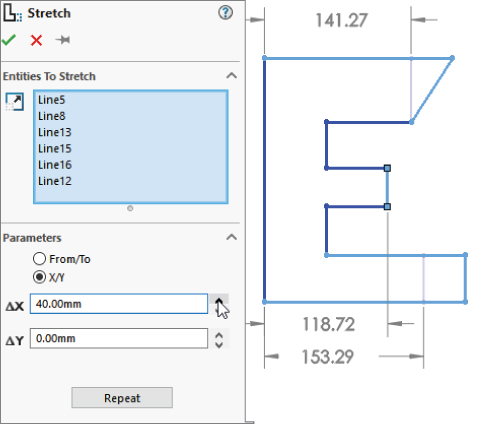
FIGURE 3.17 Using the Stretch sketch tool
![]() The Move, Rotate, Copy, and Scale sketch tools operate on selections within a sketch. You can use these tools with pre- or post-selection methods. These tools delete existing sketch relations when necessary to accomplish the task. For example, if you want to move a rectangle connected to the origin, the Move tool deletes the coincident relation between the sketch endpoint and the origin. If you want to rotate a rectangle, the Rotate tool deletes all the horizontal and vertical relations on the entities being rotated. This operation may result in a completely underdefined sketch. SolidWorks does not warn you that sketch relations are being deleted.
The Move, Rotate, Copy, and Scale sketch tools operate on selections within a sketch. You can use these tools with pre- or post-selection methods. These tools delete existing sketch relations when necessary to accomplish the task. For example, if you want to move a rectangle connected to the origin, the Move tool deletes the coincident relation between the sketch endpoint and the origin. If you want to rotate a rectangle, the Rotate tool deletes all the horizontal and vertical relations on the entities being rotated. This operation may result in a completely underdefined sketch. SolidWorks does not warn you that sketch relations are being deleted.
If you use the Scale tool on a fully defined sketch, SolidWorks scales the position of the selected entities, deleting sketch relations if necessary to do so, but no dimensions are scaled or deleted.
These sketch tools were originally put in the software to avoid some of the complexities and limitations of the Modify Sketch tool, which can also move, copy, rotate, and scale sketches. Figure 3.18 shows the simple interface for the Move Entities command. Select the entities to move in the upper box and the method to move them from the Parameters box.
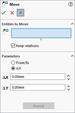
FIGURE 3.18 The Move Entities interface
![]() The Select tool is usually used to turn off the previous command and return the cursor to its default state. It is not found on toolbars in the default interface.
The Select tool is usually used to turn off the previous command and return the cursor to its default state. It is not found on toolbars in the default interface.
![]() The Grid/Snap tool is used to open the Grid/Snap section of Tools ➢ Options ➢ Document Properties.
The Grid/Snap tool is used to open the Grid/Snap section of Tools ➢ Options ➢ Document Properties.
![]() The Polygon tool creates a regular n-sided polygon in the same way as a circle. Click the center and drag the radius. You need to set the number of sides in the PropertyManager before clicking in the graphics window.
The Polygon tool creates a regular n-sided polygon in the same way as a circle. Click the center and drag the radius. You need to set the number of sides in the PropertyManager before clicking in the graphics window.
![]() An ellipse is created by clicking the center, dragging one axis, and then dragging the other axis.
An ellipse is created by clicking the center, dragging one axis, and then dragging the other axis.
![]() A partial ellipse is created by clicking the center, dragging one axis, dragging the other axis, and then clicking and dragging the included angle of the partial ellipse. The Partial Ellipse feature works like the Centerpoint Arc command.
A partial ellipse is created by clicking the center, dragging one axis, dragging the other axis, and then clicking and dragging the included angle of the partial ellipse. The Partial Ellipse feature works like the Centerpoint Arc command.
![]() A parabola is created by clicking the location for the focus and then dragging the position of the apex. You then click and drag the included angle of the parabola. This is a rarely used sketch entity and is often difficult to control with sketch relations or dimensions.
A parabola is created by clicking the location for the focus and then dragging the position of the apex. You then click and drag the included angle of the parabola. This is a rarely used sketch entity and is often difficult to control with sketch relations or dimensions.
![]() A conic is a special curve that is used to create smooth shapes that are limited to convexity on one side. A spline can have a point of inflection, but a conic cannot. It is similar to a partial ellipse, but it has an additional point called a top vertex in the PropertyManager. To create a conic, place the two end points, then place the top vertex, and finally place the shoulder. (See Figure 3.19.) If you are familiar with systems that use a rho (ρ) value, you can specify the value in the PropertyManager.
A conic is a special curve that is used to create smooth shapes that are limited to convexity on one side. A spline can have a point of inflection, but a conic cannot. It is similar to a partial ellipse, but it has an additional point called a top vertex in the PropertyManager. To create a conic, place the two end points, then place the top vertex, and finally place the shoulder. (See Figure 3.19.) If you are familiar with systems that use a rho (ρ) value, you can specify the value in the PropertyManager.
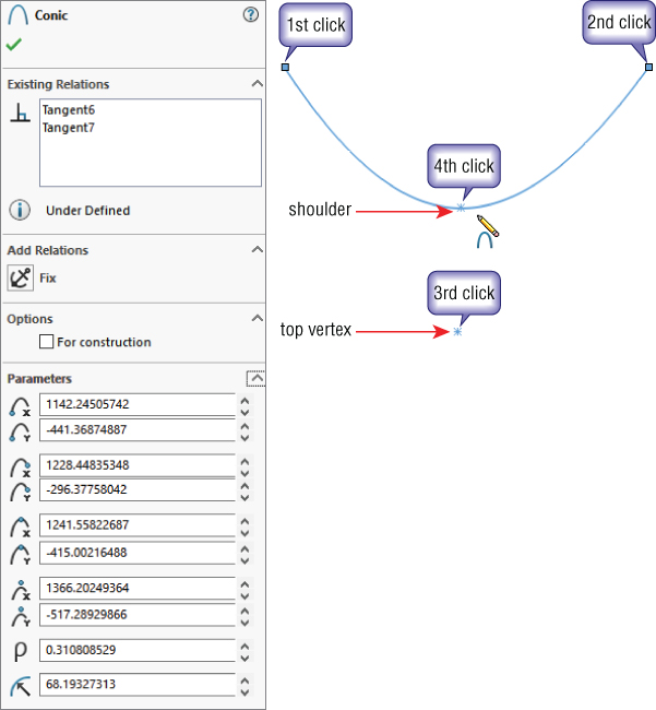
FIGURE 3.19 Drawing a conic
![]() The Spline On Surface tool is used in 3D sketches to draw a freeform spline on any 3D surface. The Spline On Surface feature can cross face boundaries as long as the faces are at least tangent (ideally curvature continuous) across the edge. Spline On Surface can be used to trim surfaces or create split lines.
The Spline On Surface tool is used in 3D sketches to draw a freeform spline on any 3D surface. The Spline On Surface feature can cross face boundaries as long as the faces are at least tangent (ideally curvature continuous) across the edge. Spline On Surface can be used to trim surfaces or create split lines.
![]() The Sketch Text tool creates editable text in sketches using TrueType fonts installed in your Windows Fonts folder. Some fonts produce sketches that are unusable for solid features, due to violating sketch rules with overlapping or zero thickness. You need to be careful which fonts you select, but I have had success with a wide variety of fonts I have found on the Internet. Sketch Text may be dissolved into lines and arcs so that you can edit them manually. Dissolve is available on the RMB menu. Figure 3.20 points out the key elements of the Sketch Text interface.
The Sketch Text tool creates editable text in sketches using TrueType fonts installed in your Windows Fonts folder. Some fonts produce sketches that are unusable for solid features, due to violating sketch rules with overlapping or zero thickness. You need to be careful which fonts you select, but I have had success with a wide variety of fonts I have found on the Internet. Sketch Text may be dissolved into lines and arcs so that you can edit them manually. Dissolve is available on the RMB menu. Figure 3.20 points out the key elements of the Sketch Text interface.
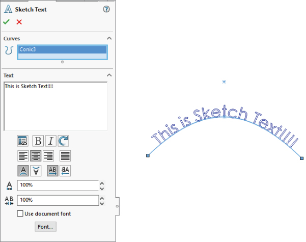
FIGURE 3.20 The text has been attached to a curve, created within the current sketch.
For some machine scribing functions, you will want single line or stick fonts. In SolidWorks, the default for that functionality would be OLF SimpleSansOC.
![]() The Intersection Curve tool creates sketch entities in 2D sketches, where the sketch plane intersects selected faces. In 3D sketches, the Intersection Curve sketch tool creates sketch entities where any types of selected faces intersect. This can be an extremely useful tool in many situations.
The Intersection Curve tool creates sketch entities in 2D sketches, where the sketch plane intersects selected faces. In 3D sketches, the Intersection Curve sketch tool creates sketch entities where any types of selected faces intersect. This can be an extremely useful tool in many situations.
![]() The Face Curves tool applies the underlying U-V isoparameter mesh to a selected face. It is most commonly used as an evaluation tool for complex surfaces, but you can also use it to create curves to rebuild faces. Accepting the results by clicking OK creates a separate 3D sketch for each spline (unless you have a 3D sketch open before clicking Face Curves, in which case you get a single 3D sketch with all of the curves). Figure 3.21 shows the original surface and the results of using face curves on a complex lofted surface.
The Face Curves tool applies the underlying U-V isoparameter mesh to a selected face. It is most commonly used as an evaluation tool for complex surfaces, but you can also use it to create curves to rebuild faces. Accepting the results by clicking OK creates a separate 3D sketch for each spline (unless you have a 3D sketch open before clicking Face Curves, in which case you get a single 3D sketch with all of the curves). Figure 3.21 shows the original surface and the results of using face curves on a complex lofted surface.
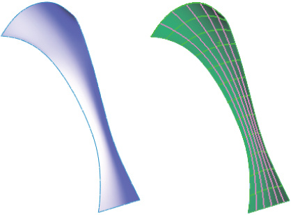
FIGURE 3.21 Using face curves on a complex surface
![]() The Extend tool extends a sketch entity up to its next intersection with another sketch entity. This is not to be confused with the Extend for surface entities. The Power Trim tool mentioned earlier can be used to extend if you hold down the Shift key while dragging the cursor over sketch entities to be extended.
The Extend tool extends a sketch entity up to its next intersection with another sketch entity. This is not to be confused with the Extend for surface entities. The Power Trim tool mentioned earlier can be used to extend if you hold down the Shift key while dragging the cursor over sketch entities to be extended.
![]() The Split Entities tool splits a sketch entity into two segments, automatically adding appropriate sketch relations and automatically adding colinear, coradial, or tangent relations for lines, arcs, and splines. You can also delete it later to rejoin the entity back into a single segment. You should be aware that the rejoining works only if there is a colinear relation between line segments, a coradial relation between arcs, or a tangent or Equal Curvature relation between splines. If you split the entity and delete these relations, they cannot be rejoined. Closed-loop entities require at least two split points.
The Split Entities tool splits a sketch entity into two segments, automatically adding appropriate sketch relations and automatically adding colinear, coradial, or tangent relations for lines, arcs, and splines. You can also delete it later to rejoin the entity back into a single segment. You should be aware that the rejoining works only if there is a colinear relation between line segments, a coradial relation between arcs, or a tangent or Equal Curvature relation between splines. If you split the entity and delete these relations, they cannot be rejoined. Closed-loop entities require at least two split points.
![]() The Dynamic Mirror command can be used when you preselect a centerline and Dynamic Mirror is turned on. Any new sketch entity that you draw is automatically mirrored to the other side of the centerline. The ends of the mirror line have hatch marks on them to remind you that you have mirroring turned on. A word of caution: If a line is drawn normal to the centerline with the endpoint on the centerline, it will just be doubled in size.
The Dynamic Mirror command can be used when you preselect a centerline and Dynamic Mirror is turned on. Any new sketch entity that you draw is automatically mirrored to the other side of the centerline. The ends of the mirror line have hatch marks on them to remind you that you have mirroring turned on. A word of caution: If a line is drawn normal to the centerline with the endpoint on the centerline, it will just be doubled in size.
![]() The Segment tool either places equally spaced sketch points along an existing sketch entity or breaks the entity up into a number of equal length segments. It acts as a pattern along a curve. The resulting segment is editable, so you can delete or add points, and they will autospace dynamically. This is an excellent tool for the Hole Wizard or for Sketch Driven Patterns.
The Segment tool either places equally spaced sketch points along an existing sketch entity or breaks the entity up into a number of equal length segments. It acts as a pattern along a curve. The resulting segment is editable, so you can delete or add points, and they will autospace dynamically. This is an excellent tool for the Hole Wizard or for Sketch Driven Patterns.
![]() The Linear Sketch Pattern tool creates a one- or two-directional pattern of sketch entities. You can define spacing and angles.
The Linear Sketch Pattern tool creates a one- or two-directional pattern of sketch entities. You can define spacing and angles.
![]() The Circular Sketch Pattern tool creates a circular pattern of sketch entities.
The Circular Sketch Pattern tool creates a circular pattern of sketch entities.
![]() The Make Path function is intended to help create machine-design motion in sketches, in particular, cam-type motion. Although it is helpful, you do not need to make a block of the cam first. You can then right-click the block and select Make Path. A tangent relation to a path enables a follower to roll around the entire perimeter.
The Make Path function is intended to help create machine-design motion in sketches, in particular, cam-type motion. Although it is helpful, you do not need to make a block of the cam first. You can then right-click the block and select Make Path. A tangent relation to a path enables a follower to roll around the entire perimeter.
![]() The Modify Sketch tool is one of the few remaining dialog box interfaces in the software that doesn't use the PropertyManager. It enables you to move, rotate, and scale the sketch, as well as mirror about a horizontal or vertical axis or about both axes simultaneously. Figure 3.22 shows the interface, which consists of a dialog box, a special origin-like symbol, and a context-sensitive cursor.
The Modify Sketch tool is one of the few remaining dialog box interfaces in the software that doesn't use the PropertyManager. It enables you to move, rotate, and scale the sketch, as well as mirror about a horizontal or vertical axis or about both axes simultaneously. Figure 3.22 shows the interface, which consists of a dialog box, a special origin-like symbol, and a context-sensitive cursor.
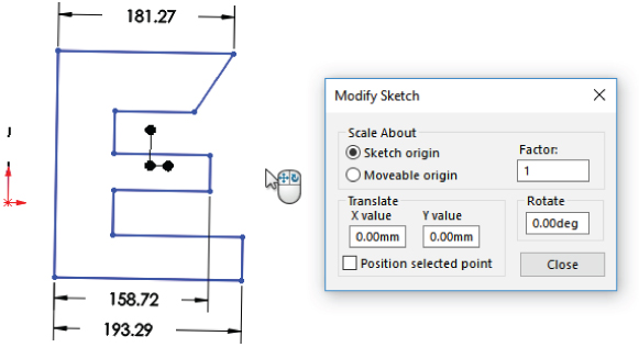
FIGURE 3.22 The Modify Sketch interface
Both the left and right mouse buttons have special functions, which change when the cursor is moved over the three knots on the special Modify Sketch origin. The RMB enables you to mirror or rotate the sketch, and the left mouse button (LMB) enables you to move the origin or move the sketch.
This function has some limitations when you use it with sketches that have external relations. Certain functions may be disabled or a warning message may appear, saying that you need to remove external relations to get a particular function to work correctly. It is best used for controlling the orientation of Derived Sketches that by default cannot have internal relations.
![]() The No Solve Move option enables the moving of sketch entities without solving any relations in the sketch. If you select this option and you move an entity with relations that would otherwise not allow it to be dragged (such as a collinear relation), you are prompted with a choice to delete the existing relation and continue or copy the entity without the relation.
The No Solve Move option enables the moving of sketch entities without solving any relations in the sketch. If you select this option and you move an entity with relations that would otherwise not allow it to be dragged (such as a collinear relation), you are prompted with a choice to delete the existing relation and continue or copy the entity without the relation.
![]() A sketch picture is a picture that is placed in the sketch, lies on the sketch plane, and is listed in the FeatureManager indented under the sketch as a child. The sketch picture may be suppressed independently from the rest of the sketch, and when the sketch is hidden, the picture is not visible. You can easily move, resize, and rotate sketch pictures, as well as apply a transparent background color to them. Sketch pictures are usually used for tracing over or as a planar decal without the need for rendering.
A sketch picture is a picture that is placed in the sketch, lies on the sketch plane, and is listed in the FeatureManager indented under the sketch as a child. The sketch picture may be suppressed independently from the rest of the sketch, and when the sketch is hidden, the picture is not visible. You can easily move, resize, and rotate sketch pictures, as well as apply a transparent background color to them. Sketch pictures are usually used for tracing over or as a planar decal without the need for rendering.
![]() The Equation Driven Curve tool creates a sketch spline driven by either an explicit or a parametric equation, as shown in Figure 3.23. An explicit equation is in the form y = f(x), while a parametric equation uses multiple equations driven by a common parameter value of the form, such as
The Equation Driven Curve tool creates a sketch spline driven by either an explicit or a parametric equation, as shown in Figure 3.23. An explicit equation is in the form y = f(x), while a parametric equation uses multiple equations driven by a common parameter value of the form, such as
- x = cos(t)
- y = sin(t)
- 0 > t > pi
where t is a number in radians.
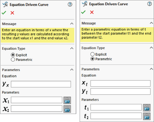
FIGURE 3.23 The Equation Driven Curve PropertyManager
The result is a proportional spline in a sketch, not a curve feature as the name suggests. You can drag the spline itself, or its endpoints, in 2D or 3D, and SolidWorks calculates the new transformation. To reposition a sketch, use sketch relations and dimensions.
If you start an equation-driven curve in a 2D sketch, you get the form for a 2D curve equation. If you start in a 3D sketch, you get the form for a 3D curve. After these splines are created, you cannot remove the relation to the equation and manually edit the spline; they are tied to the equation until you delete the entire spline.
One way to get around this limitation would be to create an equation-driven curve in one sketch and then open another sketch and use Convert Entities to copy the spline, delete the On Edge relation, and use Simplify Spline to add control points to it. This is a technique commonly used with other types of curves; it does not enable you to update the overall size or shape of the spline through the equation, but you can manually adjust sections of a curve originally created from equations. Examples of where this might be useful would be a lead-in or lead-out on a cut thread, a special attachment loop in the middle of a spring, or a flare around the edge of a lens or reflector dish for mounting.
![]() The Straight Slot and Curved Slot tools draw slots of a given width and length with full rounds on the ends. All the Slot sketch entities can be seen in the PropertyManager shown in Figure 3.24. If you need to draw a composite slot or a slot with multiple entities, you need to use the bidirectional sketch offset with capped ends mentioned earlier.
The Straight Slot and Curved Slot tools draw slots of a given width and length with full rounds on the ends. All the Slot sketch entities can be seen in the PropertyManager shown in Figure 3.24. If you need to draw a composite slot or a slot with multiple entities, you need to use the bidirectional sketch offset with capped ends mentioned earlier.
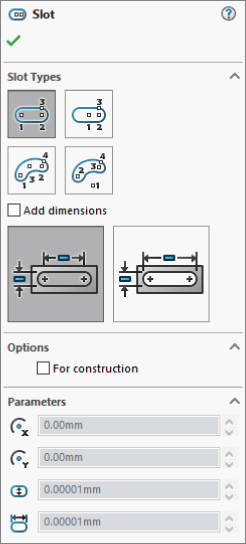
FIGURE 3.24 The PropertyManager for the Slot sketch entities
Driving Sketches with Smart Dimensions
All dimensions in SolidWorks sketches can be created with a single tool, the Smart Dimension. Dimensions are half of what you can use to drive changes in sketches with precision, the other half being sketch relations.
The Smart Dimension tool can be used to create length, point to point, aligned, angular, radial, diameter, arc length dimensions, and even reference (nondriving) dimensions.
![]() By default, SolidWorks installs with a setting called Instant2D activated. Instant2D is relatively new and has some advantages and disadvantages. One of the advantages is that it enables you to drag dimensions by the handle as shown in Figure 3.25. One disadvantage is that it disables the Modify box, shown in Figure 3.26.
By default, SolidWorks installs with a setting called Instant2D activated. Instant2D is relatively new and has some advantages and disadvantages. One of the advantages is that it enables you to drag dimensions by the handle as shown in Figure 3.25. One disadvantage is that it disables the Modify box, shown in Figure 3.26.

FIGURE 3.25 Dragging a dimension with Instant2D activated
SolidWorks sometimes forces you to use new functionality by activating it by default, instead of allowing you to decide. This is done in order for you to quickly discover new functionality. Then if you like the new functionality, you keep it; if not, you can turn it off. The downside can be a bit of initial confusion. I think in the case of Instant2D, they should allow users to turn it on if they want. The new setting adds ease-of-use at the expense of precision dimensions. If you wanted to drag type precision, you wouldn't have put a dimension on it. You can turn off Instant2D by deselecting the Instant2D tool on the Sketch CommandManager tab. The rest of the book will assume that this option is turned off.
When you place a dimension you just created, SolidWorks automatically puts you into the Modify box, which enables you to edit the dimension in several ways. You can disable this option by removing the check from the setting at Tools ➢ Options ➢ General ➢ Input Dimension Value. With that setting off, when you place the dimension, it will not display the Modify box.
You can change Smart Dimension values in several ways using the Modify box, shown in Figure 3.25. The most direct method is to key in a value such as 4.052. The software assumes document units unless you key in something specific. You can also key in an expression, even with mixed units, such as 8.5 mm/2+.125 or 25.4+.625 in. You can also key in negative dimensions, which function the same as the Change Dimension Direction button in the Modify box.

FIGURE 3.26 Using the Modify Dimension box
To the right of the drop-down arrow is a pair of up and down spin arrows that enable you to change the value in the Modify box by a set increment amount. You set the increment in Tools ➢ Options ➢ System Options ➢ Spin Box Increments. You can also store multiple increment values within the Increment Value icon on the Modify box.
The final way to change the value in the Modify box is by using the wheel underneath the value field. The wheel uses the default increment value. Pressing Ctrl while using the wheel multiplies the increment by 10, and pressing Alt while using the wheel divides the increment by 10. Once you have created the dimension and determined that you do not need the Modify box again, you can click on an existing dimension, and the Modify box will reappear with the value of the new selected dimension. Sketch dimensions can be displayed in dual units (for example, inch and millimeter), using the Dual Dimension panel of the Dimension PropertyManager. Here's a look at the Dimension Properties interface (Figure 3.27).

FIGURE 3.27 The Dimension PropertyManager tabs
- Radial: You create the dimension by selecting an arc and placing the dimension. If you want a radial dimension of a complete circle, you must right-click the dimension after you create it, select Display Options, and select the Display As Radius/Display As Diameter toggle. Alternatively, you could use the Radius or Diameter leader display options on the Leaders tab of the Dimension PropertyManager.
- Diameter: You can create the dimension by selecting a complete circle and placing the dimension. If you want a diameter dimension for an arc, use the RMB menu or Dimension Properties dialog box and select the Diameter Dimension option.
- Angle: You can create the angle dimension in two ways. If the angle to be driven is between two straight lines, simply select the two straight lines and place the dimension. If you are creating an included angle dimension for an arc where there are not necessarily any straight lines drawn, then make the Smart Dimension tool active, select the vertex of the angle, and then select the two outlying points, as shown in Figure 3.28. You can also create an angle dimension between a line and an orthogonal direction. To do this, with the Smart Dimension tool active, click on the line, and then click on the end point of a line. Four orthogonal arrows will appear. Click one of these arrows as a direction to complete the angle dimension.
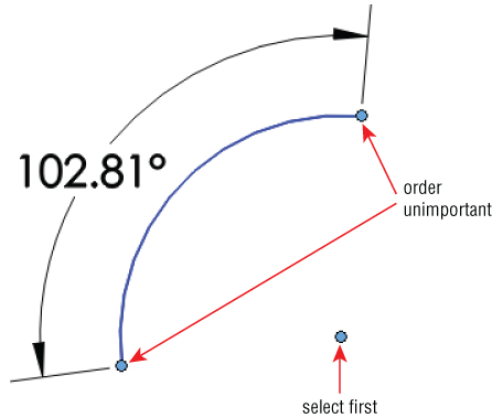
FIGURE 3.28 Dimensioning an included angle without lines
- Arc Length: You can create the dimension by selecting an arc and its endpoints with the Smart Dimension tool. This displays the actual linear length of the arc.
Using Tools on the Dimensions/Relations Toolbar
The Dimensions/Relations toolbar has a few tools that you have already seen; but as the name suggests, it also contains tools that help you to either create or investigate dimensions and sketch relations. Figure 3.29 shows the default toolbar; but in the following pages, you'll look at all the tools available at Tools ➢ Customize ➢ Commands ➢ Dimensions/Relations. These tools are available on the Dimensions/Relations toolbar:

FIGURE 3.29 The Dimensions/Relations toolbar
 Smart Dimension: Lets you dimension the sketch entity and combines several dimensioning methods into a single tool, such as horizontal, vertical, aligned, radial, diameter, and so on.
 Auto Insert Dimension: Automatically adds dimensions appropriate for selected sketch entities.
 Horizontal Dimension: Applies a dimension to a sketch entity that drives the horizontal distance between the selected points or parallel lines.
 Vertical Dimension: Works like a horizontal dimension but vertically.
 Baseline Dimensions: Creates dimensions in drawing documents only. The Baseline Dimensions tool is different from most of the dimension tools that you find on the Dimensions/Relations toolbar in that it can create driven dimensions on view geometry or driving dimensions on sketch geometry in a drawing, but the dimensions cannot be used on sketch geometry in parts. Baseline dimensions originate from a single reference; then as you select additional references, their dimensions are stacked, as shown in Figure 3.30.

FIGURE 3.30 Baseline dimension on a drawing
- Ordinate Dimensions: Drives dimensions where a set of ordinate dimensions originate from a common zero point. To use these dimensions, simply click a zero location, place the zero dimension, and then click additional points. The dimensions are placed and are automatically aligned to the rest of the dimensions.
- You can remove ordinate dimensions from the common alignment by right-clicking the dimension and selecting Break Alignment. Ordinate dimensions jog automatically if SolidWorks senses that the dimensions are getting too close to one another. You can also jog them manually. After you create the Ordinate Dimension set, you can add to it by accessing the Add To Ordinate command through the RMB menu. All the options for ordinate dimensions are shown in Figure 3.31.
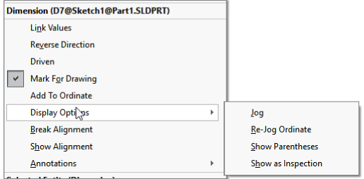
FIGURE 3.31 Options for baseline dimension
- Not all the listed options are available in the model sketch environment; some are available only in drawings.
- You can remove ordinate dimensions from the common alignment by right-clicking the dimension and selecting Break Alignment. Ordinate dimensions jog automatically if SolidWorks senses that the dimensions are getting too close to one another. You can also jog them manually. After you create the Ordinate Dimension set, you can add to it by accessing the Add To Ordinate command through the RMB menu. All the options for ordinate dimensions are shown in Figure 3.31.
![]() A chamfer dimension is another type of dimension that is only driven and only applied in drawing documents. It works by first selecting the chamfered edge and then selecting the angle reference edge.
A chamfer dimension is another type of dimension that is only driven and only applied in drawing documents. It works by first selecting the chamfered edge and then selecting the angle reference edge.
However, there is a Sketch Chamfer tool that adds dimensions to the chamfer in the sketch when the chamfer is created.
![]() The Automatic Relations toggle enables and disables the automatic creation of sketch relations while sketching. This toggle is also available through Tools ➢ Sketch Settings ➢ Automatic Relations. Automatic relations help you to create intelligent sketches with less manual intervention. Although using them takes a little practice, it is well worth the effort.
The Automatic Relations toggle enables and disables the automatic creation of sketch relations while sketching. This toggle is also available through Tools ➢ Sketch Settings ➢ Automatic Relations. Automatic relations help you to create intelligent sketches with less manual intervention. Although using them takes a little practice, it is well worth the effort.
While sketching, symbols appear on the cursor to show that a relation will automatically be created. These symbols have a yellow background and apply horizontal, vertical, coincident, tangent, parallel, and perpendicular relations. Figure 3.32 shows two situations where automatic relations are applied: a horizontal and a tangent relation.

FIGURE 3.32 Automatic relations appear on the cursor.
![]() Fully Define Sketch is a tool that can add relations and dimensions to lock down any open degrees of freedom in a sketch when the option for All Entitities In Sketch is enabled. This sounds like a better idea than it is. Although you can control how the sketch and even portions of the sketch are defined, this tool is used mainly to overcome a fear of underdefined sketches. Sketches that are just randomly fully defined are worse to work with than undefined sketches. You are better off to fully define a sketch manually. Although it may seem odd for someone in my position to say this, you are better off with a fully undefined sketch than a large sketch that is fully defined with random dimensions in it. (See Figure 3.33.) Troubleshooting something that goes wrong with a very large sketch can take a lot of time, while a fully undefined sketch can never go wrong unless you move it with the cursor. If your sketch is large, consider breaking it up in multiple features. If it has a lot of small entities, try using sketch relations, which are more flexible than dimensions.
Fully Define Sketch is a tool that can add relations and dimensions to lock down any open degrees of freedom in a sketch when the option for All Entitities In Sketch is enabled. This sounds like a better idea than it is. Although you can control how the sketch and even portions of the sketch are defined, this tool is used mainly to overcome a fear of underdefined sketches. Sketches that are just randomly fully defined are worse to work with than undefined sketches. You are better off to fully define a sketch manually. Although it may seem odd for someone in my position to say this, you are better off with a fully undefined sketch than a large sketch that is fully defined with random dimensions in it. (See Figure 3.33.) Troubleshooting something that goes wrong with a very large sketch can take a lot of time, while a fully undefined sketch can never go wrong unless you move it with the cursor. If your sketch is large, consider breaking it up in multiple features. If it has a lot of small entities, try using sketch relations, which are more flexible than dimensions.

FIGURE 3.33 Fully defining a sketch automatically can make a mess.
![]() The Add Relations tool is for those times when you have to manually add relations to sketch elements. It is generally better to use the Automatic Sketch Relations tool; but when you're editing, this is not always possible. (See Figure 3.34.) Select the sketch entity and pick the relation.
The Add Relations tool is for those times when you have to manually add relations to sketch elements. It is generally better to use the Automatic Sketch Relations tool; but when you're editing, this is not always possible. (See Figure 3.34.) Select the sketch entity and pick the relation.
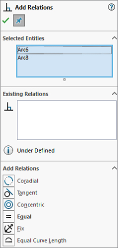
FIGURE 3.34 Manually adding sketch relations to selected entities
![]() Automatic Relations is a setting that is turned on by default. When you are sketching, it displays relations that are suggested by the sketch (such as tangent or coincident) as small yellow icons attached to the cursor (inferences are separate and are covered in the next section of this chapter) and adds those relations to the current sketch entity. Some relations displayed as small icons on the cursor do not have the yellow background, and they are not added as relations to the sketch. Figure 3.32 shows examples of automatic relations being added as sketch entities are created.
Automatic Relations is a setting that is turned on by default. When you are sketching, it displays relations that are suggested by the sketch (such as tangent or coincident) as small yellow icons attached to the cursor (inferences are separate and are covered in the next section of this chapter) and adds those relations to the current sketch entity. Some relations displayed as small icons on the cursor do not have the yellow background, and they are not added as relations to the sketch. Figure 3.32 shows examples of automatic relations being added as sketch entities are created.
![]() The Scan Equal tool searches an active drawing sketch for entities of equal length or radius. It will then set Equal sketch relations for those entities.
The Scan Equal tool searches an active drawing sketch for entities of equal length or radius. It will then set Equal sketch relations for those entities.
![]() Again, the Isolate Changed Dimensions tool is used only in drawings. This identifies any dimensions that have changed since the drawing was last saved. This will be covered in a later chapter.
Again, the Isolate Changed Dimensions tool is used only in drawings. This identifies any dimensions that have changed since the drawing was last saved. This will be covered in a later chapter.
Inferencing in Sketch
Inferencing refers to the blue dotted lines that display in Sketch mode when the cursor aligns with endpoints, centerpoints, or the origin. Inferencing creates sketch relations only when the symbol shown on the sketch cursor has a yellow background.
When the cursor displays a small sketch-relation symbol with a yellow background, an automatic relation will be applied. If the relation symbol has a white background, the relation is inferenced, but not applied, as an actual sketch relation. The symbols with the blue background are relations that have been applied to existing sketch entities. Be aware that differences in versions and differences in color schemes can cause these colors to be different on your system. (The color may be green in SolidWorks 2008 or later. The symbols look the same, regardless of background color.)
Table 3.1 shows the symbols for the various inferences, automatic relation cursors, and applied sketch relations. The difference among the three types is simply the background colors: white, yellow, and blue, respectively.
TABLE 3.1: Symbols and Their Meanings
| SYMBOL | MEANING | SYMBOL | MEANING | SYMBOL | MEANING |
| Along X | Along Y | Along Z | |||
| At Intersection of Two Faces | Coincident | Collinear | |||
| Concentric | Coradial | Equal | |||
| Equal Curvature | Fix | Horizontal | |||
| Intersection | Midpoint | Offset | |||
| On Edge | On Surface | Parallel | |||
| Perpendicular | Pierce | Symmetric | |||
| Tangent | Vertical | Display/Delete Relations | |||
| Fully Define Sketch |
Exploring Sketch Settings
In addition to sketch tools, sketch settings also control sketches. Sketch settings are found in two locations. The first location is at Tools ➢ Options ➢ Sketch. In this chapter, I cover the settings found at the second location, Tools ➢ Sketch Settings, shown in Figure 3.35. These settings mainly affect sketch relations.

FIGURE 3.35 Tools ➢ Sketch Settings
- Automatic Relations: As described earlier, it is on by default. It adds relations to newly sketched entities.
- Automatic Solve: It is also turned on by default. As you make changes to a sketch by adding relations or changing dimensions, SolidWorks automatically and immediately updates the sketch to reflect the changes. When the Automatic Solve setting is turned off, these changes are deferred until you exit the sketch or turn the Automatic Solve setting back on. The setting can be useful to prevent intermediate solutions (for example, when half of the changes are made) that may cause problems with the sketch. It can also be useful when you are confident that the outcome will be correct. It is a rarely used option, and you could probably exist just fine without even knowing this option was there at all.
- If you import a large drawing from the DXF or DWG format, these drawings import as sketch entities into either a SolidWorks sketch or a drawing. SolidWorks may automatically turn off the Automatic Solve setting for performance (speed) reasons on files of this type.
- Enable Snapping: It is also turned on by default. It enables the cursor to snap to the endpoints of existing sketch entities to help you make cleaner sketches. When you turn this setting off, Automatic Relations is also disabled (although the icon for the setting remains depressed; Automatic Relations are not created). Holding down the Ctrl key while sketching disables snapping. Holding down the Ctrl key while dragging sketch entities functions like copying sketch geometry. No Solve Move is discussed in the Sketch toolbar section.
- Shaded Sketch Contours: As described earlier, it is turned on by default. It adds shading inside of enclosed sketch areas. It enables one-click selection of all entities in the contour and moving of the contour just by dragging the shaded area.
- No Solve Move: It is also turned off by default. This rarely used option is mainly useful when moving entities within a large sketch where there are a lot of existing relations that prevent moving.
- Detach Segment On Drag: This setting is also turned off by default. When you turn it on, the Detach Segment on Drag feature enables you to pull a single sketch element away from a chain of elements. For example, if you had a rectangle and you wanted to detach one of the lines from the rest of the rectangle without using this setting, you would have to draw extra geometry and then trim and delete lines in order to release the endpoints.
- Override Dims On Drag: This setting is off by default. When you turn it on, it enables you to drag fully defined sketch geometry, and the dimensions update to match the dragged size. This is another setting that you should use sparingly. It can be useful for doing concept work, but you should leave it off when working with production data for obvious reasons.
- Pen Settings: These are covered later in this chapter in the section “Sketching with Touch Interface.”
Using Sketch Blocks
Sketch blocks are collections of sketch entities that can be treated as a single entity and can be reused within a single document or shared between documents. You can use sketch blocks in parts, assemblies, and drawings. To create a sketch block, select a group of sketch entities and click the Make Block button on the Blocks toolbar, or select Tools ➢ Blocks ➢ Make. Preselection is not necessary; you also can select the entities after you invoke the command.
Blocks may be internal to a particular document, or they may be saved as an external file. The externally saved block may be linked to each document where it is used so that if the block is changed, it updates in the documents where it is used.
You can use blocks in conjunction with the Make Path function mentioned earlier in this chapter to create functional layouts for mechanisms. You also can use blocks in an assembly to build parts in context.
Refer to Chapter 16, “Working with Assembly Sketches and Layouts,” for a more in-depth examination of the assemblies aspects of blocks in SolidWorks and to Chapter 26, “Using Annotations and Symbols,” for the use of blocks in 2D drawings.
These tools are available on the Blocks toolbar:
 Make Block: Creates a sketch block from selected sketch entities. You can position a manipulator to denote the insertion point for the block. Blocks may attach at any entity endpoint, but the insertion point follows the cursor.
 Edit Block: Enables you to edit an existing block as if it were a regular sketch.
 Insert Block: Enables you to select from a list of open blocks or browse to a location where blocks are stored. You can edit the insertion point by using the Edit Block function.
 Add/Remove: Enables you to add or remove sketch entities from the block without deleting them from the sketch while editing a block.
 Rebuild Block: Allows changes to a block to be reflected in any external relations without exiting the block. For example, if you have a block in a sketch and a sketch line is coincident to one of the endpoints in the block, you may edit the block such that the referenced endpoint moves. As a result, the line in the sketch will not move until you exit the block or use the Rebuild Block function.
 Save Block/Save Sketch As Block: Saves a selected block to an external file (with the
 *.sldblkextension) or saves the selected sketch as a block. Explode Block: Removes all the sketch entities from a block and brings them into the current sketch.
 Belt/Chain: Enables you to make a belt or chain around a set of pulleys. Each pulley must be a block. After activating the command (by right-clicking a sketch or block), you can select each pulley and use the arrow on the pulley to switch the side of the pulley to which the belt goes. You can also compensate for the thickness of the belt (this is important when both sides of the belt are in contact with pulleys) and drive the pulley arrangement using the length of the belt.
Working with Reference Geometry
Reference geometry in SolidWorks is used to help establish locations for geometry that you can't physically touch, such as planes, axes, coordinate systems, and points. (See Figure 3.36.) You often use reference geometry to establish a characteristic of the finished solid model before the model is created or to include an item that you may want to mate another part to in an assembly later. Mate references are also classified as reference geometry and are dealt with in the assembly chapters.

FIGURE 3.36 The Reference Geometry toolbar
The importance of working with reference geometry becomes obvious in situations where you need to create geometry that doesn't line up with the standard planes. You might use planes to represent faces and axes to represent the centers of holes. Axes are often used to establish a direction, such as in plastic parts where, because of draft, you never truly have any vertical edges; an axis is frequently used to establish the direction of pull for the mold.
Coordinate systems come in handy, especially when translating a part from one system to another for the purpose of machining or some type of analysis. SolidWorks users usually model in such a way that the modeling work is made simpler by the choice of how the part origin is positioned relative to features of the part; however, rapid prototyping, machining, mold building, and sheet metal manufacturing applications may have different requirements. As a part modeler, you cannot account for the needs of all downstream applications with your initial choice of origin placement, but you can always create a reference coordinate system for those downstream applications to use. Coordinate systems are fantastic as input for mates (especially for defining smart mates). They have the same functionality as origins, offering the option to define the location and the orientation with only one mate.
Creating Planes
![]() Planes are the most commonly used type of reference geometry because they are used for sketching and cutting, as extrude end conditions, and more. The Plane PropertyManager is shown in Figure 3.37. You start by selecting model items (faces, edges, points, vertices, or other sketch or reference geometry) that you want to have some relationship to the new plane. The new plane uses constraints like sketch relations from the selected references. For example, in Figure 3.37, the new plane is tangent to the selected First Reference cylindrical face and at an angle to the selected Second Reference of a plane.
Planes are the most commonly used type of reference geometry because they are used for sketching and cutting, as extrude end conditions, and more. The Plane PropertyManager is shown in Figure 3.37. You start by selecting model items (faces, edges, points, vertices, or other sketch or reference geometry) that you want to have some relationship to the new plane. The new plane uses constraints like sketch relations from the selected references. For example, in Figure 3.37, the new plane is tangent to the selected First Reference cylindrical face and at an angle to the selected Second Reference of a plane.
FIGURE 3.37 Creating a new plane from a set of selections and constraints
The good news about this method is that there are a lot more options for creating planes than in the previous method; the bad news is that the options are not all spelled out anywhere. You have to make a selection before it shows you the available constraints. You may need to experiment with this interface to see what works best for the type of modeling you do.
One of the options in the Plane PropertyManager is Flip Normal. This option has little application until you start getting into heavy parametric editing. Keep the existence of this option in the back of your head, because you will someday run into a situation where you make a change and a sketch or feature flips in an unexpected way. That will be the time to use this option.
A newer function of the Plane feature is that it will allow you to make a plane parallel to the display at a selected point. This is a somewhat hidden functionality. To enable it, you have to start the Plane command; and select a point, origin, or vertex; and then click the Parallel To Screen option.
Working with Axes
![]() You can use axes to create pivot points in a part where you do not have any hole-type geometry for mating with other parts. You can also use them as a direction of pull for plastic parts or molds. Axes are frequently used to establish direction for rotation, draft, or a number of other things. Figure 3.38 shows that the first three features in a plastic part are axes established from the standard planes.
You can use axes to create pivot points in a part where you do not have any hole-type geometry for mating with other parts. You can also use them as a direction of pull for plastic parts or molds. Axes are frequently used to establish direction for rotation, draft, or a number of other things. Figure 3.38 shows that the first three features in a plastic part are axes established from the standard planes.
FIGURE 3.38 Creating an axis to establish direction
Consider using axes set up in this way as standard features in your template files (X-, Y-, and Z-direction axes). They can be effective in assemblies for moving parts in orthogonal directions and in parts for pattern or draft directions.
Using Coordinate Systems
![]() Coordinate systems in SolidWorks are primarily used for import and export, but they also can be used for mates, mass properties, and other purposes. Coordinate systems are usually positioned by selecting a point or a set of edges to determine direction. Figure 3.39 shows the PropertyManager for assigning a coordinate system, along with the Export Options dialog box, which you can access from the Save As dialog box when the Files of Type dropdown is set to an export format.
Coordinate systems in SolidWorks are primarily used for import and export, but they also can be used for mates, mass properties, and other purposes. Coordinate systems are usually positioned by selecting a point or a set of edges to determine direction. Figure 3.39 shows the PropertyManager for assigning a coordinate system, along with the Export Options dialog box, which you can access from the Save As dialog box when the Files of Type dropdown is set to an export format.
FIGURE 3.39 Use Coordinate Systems to export parts and assemblies with a new origin location.
To use the coordinate system when saving as a translated file type such as IGES or Parasolid, click the Options button (in the Save As dialog box, after setting the translation file type). At the bottom of the Export Options dialog box, a selection box for the Output coordinate system appears.
To use the coordinate system with mass properties, choose Tools ➢ Evaluate ➢ Mass Properties from the menu, and then select the Output coordinate system, as shown in Figure 3.40.

FIGURE 3.40 Assigning the coordinate system for mass properties
Using Points as Reference Geometry
![]() The Point reference geometry feature is infrequently used; however, in some situations, nothing else does the job quite as well. This is not the same as a sketch point and does not require a sketch to be open. It is just a reference point that you can place in space. Figure 3.41 shows the PropertyManager for the Point reference geometry feature. An excellent use of this capability is to mark the center of a face.
The Point reference geometry feature is infrequently used; however, in some situations, nothing else does the job quite as well. This is not the same as a sketch point and does not require a sketch to be open. It is just a reference point that you can place in space. Figure 3.41 shows the PropertyManager for the Point reference geometry feature. An excellent use of this capability is to mark the center of a face.
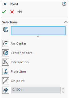
FIGURE 3.41 The Point reference geometry feature has several modes of point creation you won't find elsewhere.
The reference point and the sketch point are somewhat different in that you can use sketch points in 2D or 3D sketches, and they can be dragged or driven by dimensions and sketch relations.
Sketching with Touch Interface
Sketching with the touch interface is limited to hardware specifically developed for that purpose. You can use small Wacom tablets for the touch input, but I'm referring to large touch monitors in this case. In some cases, the touch display is able to distinguish between the use of a pen (stylus) for input and your finger. Typically, fingers are used for manipulating the view, rotation, and zoom. The pen is used for tasks that require more precision, such as selecting interface elements and sketching.
You can find special settings for Touch interface in Tools ➢ Options ➢ Touch, as shown in Figure 3.42.

FIGURE 3.42 The settings for Touch interface
Beyond the settings, SolidWorks also makes available a Sketch Ink toolbar specifically for use with the pen. This is automatically available on the CommandManager of a touch-enabled device. The Sketch Ink toolbar is shown in Figure 3.43.

FIGURE 3.43 The Sketch Ink tab of the CommandManager
The Pen tool enables you to change color and width of what is shown on the screen. If you have Auto Sketch Entities turned on, it will take your pen sketch and convert it into lines or arcs, and add an entry called Pen Sketch under the regular sketch feature in the FeatureManager. If Auto Sketch Entities is not turned on, then you will get on the screen whatever squiggle you entered with your pen. The Pen Sketch and squiggle are shown in Figure 3.44.
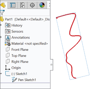
FIGURE 3.44 Pen Sketch entry in the FeatureManager and a pen-drawn squiggle on the screen
Tutorial: Learning to Use Sketch Relations
This tutorial makes sure that you get to know all the major functions in SolidWorks sketches. Almost every part that you build will start with a sketch, so this is a skill worth mastering. Follow these steps to learn about sketch relations:
- Create a folder on your hard drive called
D:LibraryBibleTemplates. You can put it where you like, but I recommend a nonsystem drive in a location where it is unlikely to be overwritten or lost. - Go to Tools ➢ Options ➢ File Locations and add a path to the Document Templates list for the location of the templates folder you just created.
 Click the New icon. In the New SolidWorks Document dialog box, make sure you see the Advanced interface. (The button in the lower-left corner should say Novice. If the button is labeled Advanced, click it to open the Advanced interface.) Click the tab in the interface that has the name of the new templates folder you just created.
- Open a new part using the template you just set up.
- If the planes are showing in the graphics window, turn them off. Go to View ➢ Hide/Show ➢ Planes. This turns off all planes. If you want to turn off a single plane, right-click the plane in the graphics window or in the FeatureManager, and select Hide.
- Select the Front plane in the FeatureManager, and click the Sketch button on the Sketch tab of the CommandManager (or right-click the plane and select Insert Sketch). Click the Line tool from the Sketch tab of the CommandManager.
- Move the cursor near the origin untill the yellow Coincident symbol appears.
 Draw a line horizontal from the origin. Remember that you can sketch the line in two ways: Click+click or click-and-drag. Make sure that the line snaps to the horizontal and that there is a yellow Horizontal relation symbol. The PropertyManager for the line should show that the line has a Horizontal relation. Also notice that the line is black, but the free endpoint is blue (after you press Esc to clear the tool). This means that the line is fully defined except for its length. You can test this by dragging the blue endpoint.
- Click the Smart Dimension tool on the Sketch toolbar; use it to click the line that you just drew, and place the dimension. If you are prompted for a dimension, type 1.000. If not, then double-click the dimension; the Modify dialog box will appear, enabling you to change the dimension. The setting to prompt for a dimension is found at Tools ➢ Options ➢ General, Input Dimension Value.
- Draw two more lines to create a right triangle to look like Figure 3.45. If the sketch relations symbols do not show in the display, turn them on by clicking View ➢ Sketch Relations. You may want to set up a hotkey for this, because sketch relations are useful but often get in the way. When you enclose the triangular area, SolidWorks will shade the triangle if the Shade Sketch Contours is active. This tool is by default on the right end of the Sketch CommandManager tab.
FIGURE 3.45 Draw a right triangle.
 Drag the blue endpoint of the triangle. Dragging endpoints is the most direct way to change the geometry. Dragging the line directly will also work by causing the angle of the line to change. The sketch leaves a ghost when dragging so that you can see where you started. Note that the setting for leaving a ghost when dragging a sketch is found at Tools ➢ Options ➢ Sketch, Ghost Image On Drag.
- Click the Smart Dimension tool, and then click the horizontal line and the angled line. This produces an angle dimension. Place the angle dimension and give it a value of 30 degrees.
 Click the Sketch Fillet tool, set the radius value to 0.10 inches, and click each of the three corner points. Press OK in the PropertyManager, OK in the RMB menu, or Enter on the keyboard to accept the preview of the fillet. SolidWorks creates a virtual sharp at the ends of the horizontal line to preserve the connection points for the 1.00 dimension. Figure 3.46 shows the sketch at this point. You may now want to turn off the Sketch Relations display because the screen is getting pretty busy. You can find this setting at View ➢ Hide/Show ➢ Sketch Relations, or use the Heads Up View toolbar for quicker access.
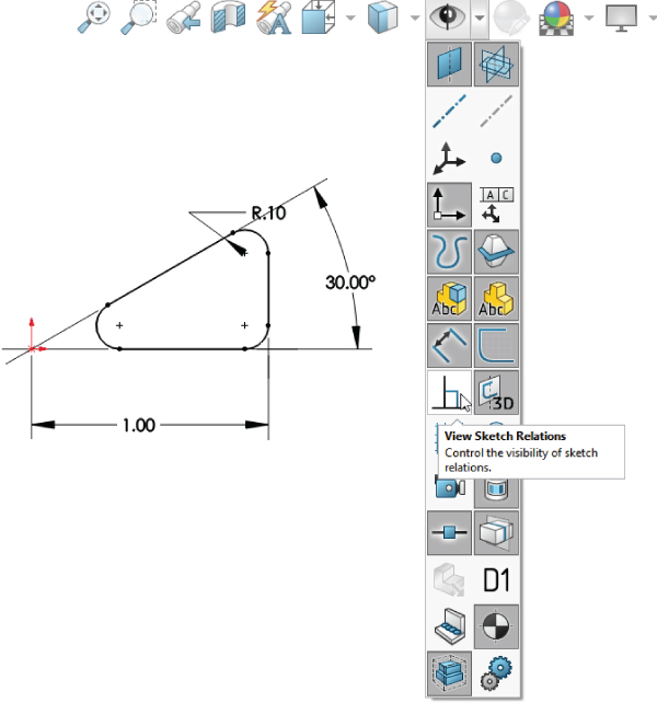
FIGURE 3.46 Add a sketch fillet.
- Draw a line starting from the midpoint of the angled line. The midpoint should highlight when you move the cursor close to it. Draw the line perpendicular to the angled line. A dotted yellow line appears, showing where the perpendicular lies. When you follow this line, the yellow perpendicular symbol appears on the cursor. Make this line approximately 0.12 inches long. Feedback on the cursor also shows the length of the line as you draw it.
- Draw two more lines ending at the endpoint of the sketch fillet, as shown in Figure 3.47. Use the Inferencing lines to line up the second angled line with the end of the arc.

FIGURE 3.47 Add some lines.
 Click the Trim tool from the Sketch toolbar. Make sure that the Trim option is set to Closest. Click the angled line of the triangle between the two lines sketched in step 15. This trims out that section and makes the sketch a single closed loop. A warning may appear because you have a midpoint relation to the line being trimmed; you no longer want this relation, but you want the lines to intersect at their endpoints. Select Yes at the prompt.
 Add a sketch relation. Click on one of the two parallel lines and then Ctrl+click on the other. Now click Equal in the PropertyManager to make these two lines equal length.
- Add smart dimensions. Click the Smart Dimension tool and add an aligned dimension to one of the lines just set as Equal. Make this line 0.125 inches. This turns one line black, so add a dimension to the black line to make it 0.25 inches. The result is a fully defined sketch, as shown in Figure 3.48.

FIGURE 3.48 A fully defined sketch
 Save the part with the name
 Sketch Relations Tutorial1.sldprt. Close the part.
Tutorial: Using Blocks and Belts
Sometimes I am amazed at the things that can be done in SolidWorks, even with fairly simple tools. This is one of those times. If you design machines, this tutorial has some extra meaning for you. Blocks and Belts are a valuable toolset for various situations. Follow these steps to learn about using Blocks and Belts.
- Open a new part with inches as the units.
- Draw and dimension a sketch on the Front plane connected to the origin as shown in Figure 3.49. Exit the sketch and rename it Layout Sketch, either by clicking twice (slow double-click) on the name of the sketch in the FeatureManager or by selecting it and pressing F2.
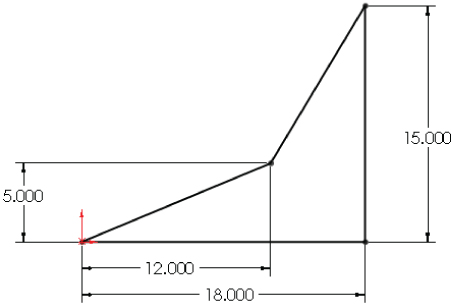
FIGURE 3.49 The layout sketch
 Exit the sketch by clicking the Confirmation Corner Exit Sketch symbol in the upper-right corner of the graphics window (not the red X).
- Open a second sketch on the Front plane and draw a circle with a 6-inch diameter centered on the origin. This needs to be a second sketch, not just reopening the first sketch.
 Inside the circle, draw a Centerpoint rectangle centered on the origin.
 Select two adjacent sides of the rectangle and make an Equal sketch relation between them. This makes the rectangle into a square, but still doesn't define its size.
- Click the Smart Dimension tool and apply a 1.000-inch dimension to one side of the square. Turn off the Smart Dimension tool by clicking it again on the toolbar or pressing Esc.
- If the Blocks toolbar is not active, activate it and then select Make Block. You also can access this command through Tools ➢ Block ➢ Make.
 Window select the circle and the square by clicking and dragging a box that includes all the items in the sketch. The PropertyManager to the left displays a circle and six lines that are to be made into a block. SolidWorks by default forces you into using the Lasso selection. You can switch to Box selection in the Tools menu, or in Tools ➢ Options ➢ Selection, Box. This would be a good tool to put on a hotkey.
- Expand the Insertion Point panel in the PropertyManager. This causes a blue manipulator origin to appear in the graphics window. Click this origin and drag it onto the center of the circle. Then click the green checkmark icon to exit the Make Block dialog box, as shown in Figure 3.50.
FIGURE 3.50 Making a block
- The items in the block now turn gray. Click anywhere on the block and drag it out of the way. Then drag the center of the circle and drop it on the part origin.
- Click the Insert Block tool on the Blocks toolbar. There should be only a single block named Block1 in the Open Blocks box. Place the block on the opposite sharp corner of the layout sketch.
- Create another block that is identical to the first one, except with a diameter of 3 inches instead of 6 inches. You can do this by selecting the first block, clicking Edit Block from the toolbar, and copying (Window select and Ctrl+C). Then exit the Edit Block and paste (Ctrl+V) in the regular sketch. Make sure to also change the insertion point for this second block to the center of the circle
- Insert a second instance of this second block, and make sure that both of them have the center of the circle at the two remaining intersection points of the four-sided shape of the layout sketch. At this point, your sketch should look like Figure 3.51.

FIGURE 3.51 Block placement
- Click the Belt/Chain tool on the Blocks toolbar. Select the blocks in counterclockwise order, starting at the top pulley so that they go in the Belt Members selection box, as shown in Figure 3.52. On the last pulley, you will have to click the Flip Bent Side arrow to get the belt to go the correct way around the pulley. If this doesn't work for you, clear the selection box and try to select the pulleys in a different order. Press F on the keyboard to get the display to Zoom to Fit.
FIGURE 3.52 Belt placement
- Make sure that the Engage Belt option is selected. This will enable you to make the pulleys move in the same way that they would in a real belt-driven mechanism. This will help you calculate the required length of the belt.
- Click the Use Belt Thickness option and assign 0.25 inches for the thickness. The belt should be offset from the pulleys.
- Click the green checkmark icon.
- Click and drag one of the corners of the square in a pulley. All the pulleys should turn as if they were real mechanisms. The ratios are also observed because the small pulleys rotate faster than the large ones.
- Save this part as
Blocks and Belts Tutorial.sldprt. Exit the part.
Tutorial: Creating Reference Geometry
This tutorial steps you through creating reference geometry on an existing part in preparation for locating 3D features.
- Open the file from the download materials in the Chapter 3 folder called
Chapter 3 Reference Geometry - start.sldprt.  In the FeatureManager filter, type plane1. Double-click Plane1 in the FeatureManager. Double-click the 3.25-inch dimension on the screen and change it to 3.35 inches. Click the rebuild symbol (traffic light) and watch the update. This plane locates the mounting base of the part. Click the green check mark to accept the change and exit the Modify box.
 Click the Axis toolbar button from the Reference Geometry flyout menu (on the Features tab of the CommandManager in a default install).
- Select the inside face of a hole on the part, as shown in Figure 3.53. This creates an axis on the centerline of the hole. You should note that temporary axes are automatically created for all cylindrical faces, but making a true axis feature helps this one stand out as different from the other holes on the part. The selection of the Cylindrical/Conical Face option is automatically activated by your selection of the cylindrical face of the hole. Accept the result with the green check mark when the selections and settings are complete.

FIGURE 3.53 Creating an axis
 Click the Plane toolbar button from the Reference Geometry flyout on the Features tab of the CommandManager.
- Select the large cylindrical face of the part as the First Reference and the axis you just created as the Second Reference. (Go to View ➢ Hide/Show ➢ Axes if you cannot see the axis.) Make sure the First Reference uses the Tangent constraint and the Second Reference uses the Coincident constraint. This makes a plane tangent to the main cylinder in the part that goes through the patterned hole, as shown in Figure 3.54. Click the green check mark to accept the result.
FIGURE 3.54 Creating a plane
- Open a new sketch on the new plane.
- Click the View ➢ Hide/Show menu and activate the Temporary Axes option. You should now see blue axes (without names) appear along the centerlines of every conical or cylindrical face on the model (except for faces created by fillet or chamfer features).
 Select the sketch plane either from the graphics window or the FeatureManager. Press the spacebar on the keyboard and double-click Normal To. You can click the pushpin to keep this box available. There are other ways to access this command, but this is the method that works regardless of your interface setup.
- Use the Centerpoint Rectangle to create a rectangle centered around the temporary axis of the large cylindrical face. Make sure that the centerpoint, which is the first click you make, picks up a coincident automatic relation with the temporary axis. Make sure the second click to place the corner of the rectangle does not pick up any automatic relations. This is shown in Figure 3.55.
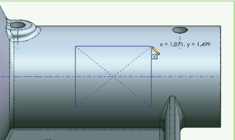
FIGURE 3.55 Creating a rectangle centered on the temporary axis
You can tell if any relations have been applied if you go to the View ➢ Hide/Show menu and activate Sketch Relations. Make sure the centerpoint has a coincident relation and that none of the corners has any relations.
- Use the Smart Dimension tool to apply dimensions, as shown in Figure 3.56. Note that the 3.450-inch dimension goes to the part origin on the left. You can select this from either the graphics window or the FeatureManager.
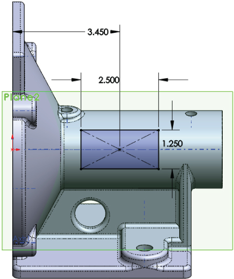
FIGURE 3.56 Creating a rectangle centered on the temporary axis
 Click the Extrude toolbar button on the Features tab of the CommandManager. Rotate the model (by dragging with the mouse wheel depressed) slightly so you can see the side of the extrusion preview, as shown in Figure 3.57.
 You may have to adjust the direction of the extrude using the icon with the arrows just below the Direction1 heading in the Boss-Extrude PropertyManager.
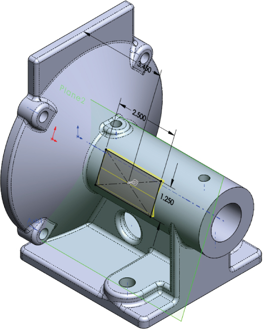
FIGURE 3.57 Creating the extrusion
- Use the Up To Next end condition, which makes the extruded solid go up to the next solid that it encounters.
- Use the View menu to turn off the display of Axes, Temporary Axes, and Planes.
The Bottom Line
- Create new sketches and edit existing ones. In SolidWorks, each sketch is named and must be on a plane or planar face. You can edit only one sketch at a time, and there are things you cannot do while in a sketch.
- Master It Practice creating new sketches and using the various sketch entities on the Sketch toolbar to familiarize yourself with the range of tools that are available and how they work.
- Create new reference geometry and use the planes to create new sketches. As you get deeper into this book, you will learn more uses for the Reference Geometry tools. For now, the primary function is to establish planes for sketches without relying on adding relationships to solid geometry.
- Master It Practice moving or redefining planes to see how the change affects the resulting 3D geometry. Also build your skills by creating planes using the available options. If you can imagine a way to define a plane, use the three selection boxes and available constraints to see how many different types you can create.
- Use a range of sketch entities. While you can often get by using just lines and arcs, there are times when more advanced sketch entities are more appropriate. Ellipses, parabolas, conics, splines, even slots, polygons, and sketch text are all valid sketch entities that are very useful in certain situations.
- Master It Practice using some of the more advanced sketch entities on the Sketch toolbar.