
Chapter 35
Creating Sheet Metal Drawings
After you create your sheet metal models, you will need to make drawings to use to get them manufactured. Fortunately, SolidWorks provides some nice tools to document, dimension, and annotate your parts in 2D.
Depending on whether your company does its own sheet metal manufacturing, you may or may not actually make flat pattern drawings. Many companies that use outside manufacturing for their sheet metal parts may just send their suppliers a drawing with views of a dimensioned part in the folded state. This is because the final formed dimensions are what you want the shop to be responsible for, and if they use different flat dimensions to achieve that, it doesn't really matter.
Many users may think that providing a fully dimensioned flat pattern is very valuable to the sheet metal shop. If your sheet metal shop is a professional outfit, they probably have their own software and their own way of doing things; in which case, a flat pattern is redundant information and may create more confusion than clarity.
On the other hand, if you are the sheet metal shop, or you specifically create drawings for the sheet metal shop, then creating the flat pattern is actually your business. This chapter gives you all the information you need to know to make sheet metal drawings, regardless of your role and without trying to tell you how to do your job. It's best to work out with the shop what data will make the process the fastest and cheapest with the fewest errors.
Making Sheet Metal Drawings
Sheet metal drawings can take on various roles in your product development process—anything from general “make me a part that looks like this” to actually specifying how the work is to be done. Some drawings may need only the flat pattern or only the formed part. Here I'll assume that a sheet metal drawing requires both the formed and flat part, just to cover as much ground as possible.
If you need a drawing with both formed and flat geometry, you might consider making a two-page drawing—one page with the flat pattern and the other page with views of the 3D part. You might use one drawing sheet for the press operator and the other sheet for inspection. If you need only the flat pattern, you might consider using an isometric view of the part just for reference.
If your sheet metal parts are welded together with other sheet metal, structural, cast, stamped, or plate parts, you might want to refer to the section later in this chapter on multibody sheet metal drawings. You can accomplish the same things with an assembly (and in some cases, the assembly will be the better option), but many people think that modeling in multibodies is easier. Sheet metal multibody techniques are a little different—and in my opinion, they don't offer as many advantages as normal multibody techniques. If you must work in this mode, be careful to leave room on your drawing for exploded views and a weld list. Flat patterns require some extra thought if you have multiple sheet metal bodies in a single part.
You may also want to make a special drawing template for sheet metal drawings. The special template can contain custom blocks, title blocks, or table anchors.
Getting the Flat Pattern
When you need to make a drawing to use for building a sheet metal part, getting the flat pattern is an essential part of the process. SolidWorks provides several ways to develop the flattened bend sections in the K-Factor, bend allowance, bend deduction, and bend calculation tables. Getting these values or equations correct is key in making the flat pattern the correct size to produce the finished part accurately. Chapter 34, “Using SolidWorks Sheet Metal Tools,” covers how to use these methods, but you should obtain the actual values from your sheet metal shop.
You create the drawing of a sheet metal part in the same way that you would create one for any other type of part. You can use one of several methods, including using the Create Drawing From Part command or dragging and dropping the part onto a drawing. Sheet metal drawings may serve different purposes. Usually, a sheet metal drawing requires dimensioned orthogonal views of the finished part, and sometimes, it also requires a flat pattern describing the blank from which the finished part is to be formed.
To show a view of the flat pattern on a drawing where you already have a sheet metal part, select the view from the FeatureManager or the graphics window, and in the list of views below the Standard Views area of the Orientation panel of the PropertyManager, select Flat Pattern from the list. The Drawing View PropertyManager is shown in Figure 35.1.

FIGURE 35.1 Converting a view of a sheet metal part to a flat pattern
This won't work from a projected view, and if you have placed a named view, SolidWorks may change the view of the part to lay the flat pattern down on the sheet.
Understanding Flat Patterns and Configurations
When a sheet metal part is put onto a drawing, SolidWorks automatically creates a derived configuration called SM-FLAT-PATTERN. The configuration doesn't exist until the part is put onto a drawing. For a part made with the Base Flange Sheet Metal method, the derived configuration in Figure 35.2 shows the default arrangement.
![Selected Configurations button displaying the default arrangement with icons for Chapter 35 – Sheet metal 1 Configurations(s) (Default), Configurations Comments, and Default [ Chapter 35 – Sheet metal 1 ].](http://images-20200215.ebookreading.net/2/1/1/9781119300571/9781119300571__mastering-solidworks__9781119300571__images__c35f002.jpg)
FIGURE 35.2 Automatically created derived configuration for the flat pattern
If your part already had multiple configurations, only the configuration that’s shown on the drawing would display a derived flat pattern. If you later show another configuration on the drawing, the derived flat pattern won't automatically be created until you show a flat pattern of that configuration.
There's a second way to get a flat pattern of a sheet metal part on the drawing. If you use the drop-down list in the Reference Configuration panel of the Drawing View PropertyManager, you can select the derived-flat-pattern configuration from there. The flat patterns that you get using these two methods may be oriented differently, and if you use the Flat Pattern selection from the More Views options, you also will get bend lines and annotations marking the direction, angle, and inside radius of the bend. The difference between the resulting views of these two methods is illustrated in Figure 35.3.
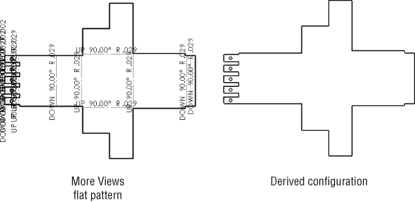
FIGURE 35.3 Comparing flat pattern views placed by using the More Views options or by showing the derived-flat-pattern configuration
The PropertyManager for the flat pattern view contains many settings that are not shown or discussed here. You may find it useful to explore the entire contents of the PropertyManager for the view to see other items you can control, which include rotation of view, scale, quality of view and cosmetic threads, and many others.
Showing Bend Lines and Bend Notes
If you show the derived configuration, the bend lines are not included in that view. To turn on the bend lines, you need to go to the FeatureManager for that view, scroll to the Flat Pattern feature, expand it, right-click the Bend Lines sketch, and select Show.
Figure 35.4 shows the Drawing FeatureManager with the Bend Lines sketch highlighted.
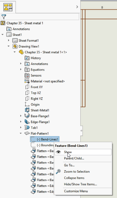
FIGURE 35.4 Turning on the bend lines for a flat pattern view
To get the bend notes to show up, you need to use the Drawing View PropertyManager Bend Notes panel, shown in Figure 35.5.

FIGURE 35.5 Showing the bend notes for a flat pattern
You can configure the content of the bend notes using the Text Box and the Syntax buttons. These buttons, located at the bottom of the screen, represent, in order from left to right:
- Bend Direction
- Supplementary Angle
- Complementary Angle
- Bend Radius
- Bend Order
- Bend Allowance
Other options for the display of bend notes are also available. Select Tools ➢ Options ➢ Document Properties ➢ Sheet Metal ➢ Bend Notes ➢ Style, and you can choose from the following options:
- Above Bend Line
- Below Bend Line
- With Leader
When the notes are above or below the bend lines, they are aligned with the bend line, so the notes could be horizontal, vertical, or angled. If there's a succession of bends, interrupted in some way but close to one another, these notes can be on top of one another and difficult to read.
If you use the With Leader option, all notes are horizontal with respect to the drawing sheet, and a leader points to the bend line.
You should explore the settings at the above-mentioned Tools ➢ Options location, as there are several in this location that can help you control the appearance of the bend notes, including Layer, Color, Line Type, Font, Border, and so on. Notice, too, that you have the powerful functionality that covers the insertion of Cut List Properties in the drawing.
Showing the Bounding Box for the Flat Pattern
SolidWorks automatically calculates a bounding box for your sheet metal flat pattern. This is the smallest rectangle into which the flat pattern will fit. This can be useful if your manufacturing process cuts the flat pattern from individual blanks rather than a bigger sheet with nested flat patterns. Generally, the bigger sheet allows you greater material efficiency, but it may also be difficult to manage if you don't have the equipment, and it may be unnecessary if you are making low volumes of certain parts.
The bounding box may not be aligned the way you might expect, but it represents the smallest rectangle that SolidWorks calculates will include your flat pattern. Many shops have separate nesting software that may allow for custom fits or some additional options. If you're not sure if your shop would benefit from a bounding box on the drawing, you may want to ask directly.
You can have some control over the bounding box. If you specify a grain direction in the Flat Pattern PropertyManager, the bounding box will align with the grain direction. You can use an edge, an axis, or a sketch to define the grain direction. The grain direction is the pattern of streaks on the face of the sheet metal that indicates the direction the sheets were processed in fabrication. Sheet metal properties can vary somewhat if measured with and against the grain. Sometimes, the grain is specified in a certain orientation for aesthetic reasons.
The bounding box is stored in the sheet metal part as a sketch, which you can see right below the Bend Lines sketch shown in Figure 35.4. You can show this sketch, and the drawing will display it as a construction line. Figure 35.6 shows a flat pattern with a bounding box.
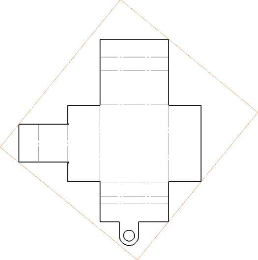
FIGURE 35.6 Showing a bounding box on a drawing
Showing Bend Areas on the Part
If you want to show or hide the bend areas for all bends on the flattened part, open the part in its own window and edit the Flat Pattern feature. You cannot edit the feature from the drawing; you must do it from the part's own window. In the Flat Pattern PropertyManager, make sure the Merge Faces option is turned off.
Figure 35.6 shows the bend lines (Merge Faces) turned off, and Figure 35.7 shows the bend lines (Merge Faces) turned on. Figure 35.7 also shows the Bend Area setting that's available from the model. In Figure 35.7, the Tangent Edges are set to use a font. You can find this setting at View ➢ Display ➢ Tangent Edges With Font or on the RMB menu for the view.

FIGURE 35.7 Showing the tangent bend lines on a flat pattern
As a note, when showing a flat pattern of a part using welded corners, the welded corners must be suppressed before the flat pattern can be shown. This is the case with the part used in the Figure 35.7.
Making Drawings of Multibody Sheet Metal Parts
You cannot flatten multiple sheet metal bodies simultaneously within a single sheet metal part. However, SolidWorks is adding more capabilities for drawings of multibody parts. You might do best to use them as a bridge to a single body, or when other parts such as small welded bits or PEM fasteners are pressed into a sheet metal part, creating an inseparable subassembly.
Figure 35.8 shows two different part scenarios that this chapter addresses. The part on the left is a simple sheet metal part with PEM standoffs from the SolidWorks Toolbox pressed into holes. The part on the right is a sheet metal part with multiple sheet metal parts and a simple plate, intended to be welded together.
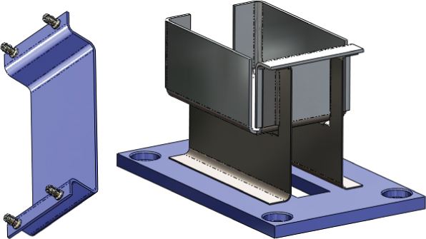
FIGURE 35.8 Two multibody sheet metal scenarios
Both methods are valid uses of multibody sheet metal parts.
Displaying Bodies on the Sheet Metal Drawing
SolidWorks allows you to hide bodies within a drawing view. To do this, click inside the view. At the top of the PropertyManager for the view in the Reference Configuration panel is a button labeled Select Bodies; use this button to change the bodies that are visible in the drawing view. The Select Bodies button and the Body Selection list are shown in Figure 35.9.
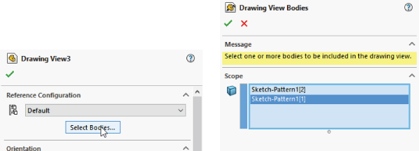
FIGURE 35.9 Selecting the bodies to show on the drawing
The functionality that allows you to use the part color on the drawing doesn't apply to bodies. If you use this setting, all the bodies use the part color. If your part uses an appearance, a color is always part of the appearance assignment, although the part may not display the color. For example, a steel appearance may still have a blue color assigned. You will see the texture-like appearance when the part is shaded, but you will see the associated color when the part is shown in Wireframe mode.
Using a Cut List in a Sheet Metal Part
When you create a new sheet metal part, the FeatureManager automatically gets a new item called a cut list. The cut list is technically called a “Weldment Cut List,” but it's used in sheet metal as well as in weldments to keep track of the parts modeled as bodies. The cut list is not very interesting until you have multiple pieces to list, and this happens in a part file only when you have multiple bodies. Beyond using multibodies as an interim condition where you're bridging between bodies, the cut list is used when the final model is intended to have multiple bodies. The real use of the cut list is to list on the drawing each of the individual pieces that go together to make the finished part. These pieces can be purchased hardware, other sheet metal parts, or welded plate parts, among other items.
You can add several types of values to the cut list. It's essentially a Bill of Materials for welded assemblies. To access the interface for Cut List Properties, right-click the Cut List folder and select Properties. Figure 35.10 shows a default Cut List Properties table.

FIGURE 35.10 Managing the properties for a sheet metal cut list
Managing Cut List Properties
To fill out the Cut List Properties, use the Cut List Summary the same way that you would use the Custom Properties data entry. Notice also that several properties already exist for the cut list. These include sheet metal–specific items like Bounding Box Length, Sheet Metal Thickness, the number of bends, material, or a special cut-list-specific description. You can add more custom properties as well.
Notice that on the left in Figure 35.10 is a list of all the cut-list items. This enables you to set the properties for each item. Although most of the values use automated syntax, others, like the Description or any custom properties you might add, require manual data entry.
The next step after arranging all your Cut List Properties is to create a drawing and add the cut list to a view.
When you create a drawing of a multibody sheet metal part, you can place the cut list on the drawing.
Placing the Cut List on the Drawing
After you create the multibody sheet metal part, filled out the Cut List Properties, and created at least one drawing view of the part (flat or formed), you'll be ready to put a cut list on the drawing. I will assume you're placing a default cut list and then need to create a customized one later. The next section also describes how to create a cut list template after you have made one to suit your needs.
With the multibody sheet metal drawing active, select Insert ➢ Tables ➢ Weldment Cut List. The Weldment Cut List PropertyManager is shown in Figure 35.11.

FIGURE 35.11 Configuring a Weldment Cut List for a multibody sheet metal part
The first option in the Weldment Cut List PropertyManager is to select the template. By default, there's only the single sample table, which you probably need to customize somewhat to suit your needs. You'll do that shortly.
After you have set the options to your satisfaction, place the cut list on the drawing by clicking where you want to place the table. Notice that as you drag the table around, it snaps to the drawing format border. You can place it at one of these snap locations or just place it in a blank area on the drawing.
When you select a column header (labeled with a letter), a Column PropertyManager will appear, along with a text-formatting bar. This is all shown in Figure 35.12.
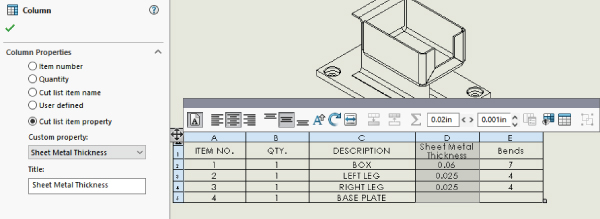
FIGURE 35.12 Customizing the Cut List column
From there, you can change the information in the selected column. The first three column properties are built-in properties: Item Number, Quantity, and Description (cut-list item name). The User Defined option lets you manually enter whatever text you want. The Cut List Item Property option allows you to select from a list of automated values, shown in Figure 35.12.
You can add additional columns by right-clicking a column and selecting Insert ➢ Column Right or Column Left. The additional columns can be formatted like the others.
Saving a Cut List Template
After you have customized the cut list the way you like it—with the automated or manual entry fields set up to save you time the next time you need to use a similar table—you can save the table as a template. Right-click the table and choose the Save As option. The file type that is assigned is *.sldwldtbt. This long-file extension presumably stands for “Weld Table Template.” Although a weld table and a cut list are not necessarily the same thing, they do use the same templates.
Save the template file in the location established for your Weldment Table templates. You can find them at Tools ➢ Options ➢ File Locations ➢ Weldment Cut List Templates, which by default points to C:Program FilesSolidWorks CorpSolidWorkslangenglish, but you can (and should) keep all your custom templates in a path that won't be overwritten by reinstalling or uninstalling the software—and a place that multiple users can share if necessary.
The next time you need to use this template, you can select it using the Table Template drop-down list in the Weldment Cut List PropertyManager.
The Bottom Line
SolidWorks has lots of special drawing functionality built around sheet metal parts. You may want to create a special template or format for sheet metal drawings or even use multipage drawings for including both flat and formed views of the part.
Multibody modeling in sheet metal opens another range of possibilities in documenting inseparable subassemblies and small weldments using sheet metal parts. The use of a cut list is similar to the use of a BOM, and though originally intended for weldments, it's also useful for sheet metal parts.
- Master It Create a blank drawing using a B-size template that has a second page (for example, the
Mastering 2pg B size.drwdot). Remove any predefined views.Create a flat-pattern-drawing view of the part
Chapter 35 - Master It 1 start.sldprt.Apply bend notes to the view.
Show bend lines without bend areas,
Show the bounding box on the flat pattern view.
On the second page, place an isometric view of the part, in Shaded With Edges mode.
Make sure the custom properties from the part have filled out the title block information.
Scale the isometric view at 2:1.
- Master It Apply ordinate dimensions in horizontal direction for the major edges and baseline dimensions vertically.
- Master It On the second page, place an isometric view of the part, in Shaded With Edges mode.
Make sure the custom properties from the part have filled out the title block information.
Scale the isometric view at 2:1.