
Chapter 16
Working with Assembly Sketches and Layouts
When you're working on parts or assemblies, design work will often begin with 2D sketches. In the previous chapter, we used assembly sketches to drive patterns. You can follow through to 3D with data created in this phase by laying out the design as a sketch in the assembly before you start making actual 3D parts. When you use a single sketch or multiple sketches either as a visual guide or as a functional framework for a model, the visual guide is called a layout. Two-dimensional sketches are easy to produce and easy to use as the first step in design or modeling work. SolidWorks provides both formal and informal techniques for achieving this sort of effect.
The topic of layout sketches involves other topics, such as in-context modeling and master model techniques, which are covered in more detail later in this book. These topics are introduced here at a conceptual level to prepare you for the detailed information later.
In-context modeling involves the creation of relationships between parts in an assembly such that one part drives features on another part. Layout concepts apply to in-context modeling because you can use an assembly-level sketch to drive geometry within individual parts.
Looking at the Techniques
An informal technique called an assembly layout sketch has existed since early versions of SolidWorks. This technique has been included in the SolidWorks official training materials for many years, and it simply allows an assembly-level sketch. You can do one of several things with the sketch: build parts in place on it, use it to drive component patterns, mate parts to it, or use it to cut up a single part into multiple pieces. You can also adapt the assembly layout sketch technique for use as a single point of reference when you need to change multiple features within a single, highly complex part.
![]() The formal assembly feature is called the Layout. The Layout is an assembly-level 3D sketch that displays a specific icon and has some special properties. Although the formal feature and the informal technique have similar names, they have very different functions.
The formal assembly feature is called the Layout. The Layout is an assembly-level 3D sketch that displays a specific icon and has some special properties. Although the formal feature and the informal technique have similar names, they have very different functions.
In this book, the word layout is used with a lowercase “l” to refer to the informal assembly-based sketch layout method. The formal assembly-based 3D sketch with special properties is referred to with a capital “L” as a Layout. The Layout icon from SolidWorks may also accompany the formal feature.
Using the Assembly Layout Sketch
In SolidWorks, layout sketches are a great way to simulate mechanisms or to locate the major components of an assembly. Figure 16.1 shows three examples of assemblies created with the assistance of an assembly layout sketch.

FIGURE 16.1 Assembly layout sketches can be used in a wide range of applications.
The bicycle example is used throughout this book, and the layout sketch was instrumental in establishing the geometry of the frame, wheels, and fork. Most of the components of a bicycle are purchased as off-the-shelf items that may come in different sizes but are not custom-created for individual bikes. The only parts that are generally custom-built for a particular size are the frame and possibly the fork. Therefore, to design the frame, you must lay out all the data that you are given for the individual components, such as wheels, stem, crank set, and seat. When you put everything together, additional pieces of information determine the frame geometry before the detail design of the frame can be started. You need to know the following:
- The size of the wheels
- The wheelbase (distance between the wheel centers)
- The length of the pedal arm
- The necessary clearance between the bottom of the pedal and the ground
- The head angle (effective pivot angle of the front fork)
- The distance between the center of the crank and the center of the rear wheel
The workflow for using an assembly layout sketch is as follows:
- Open a new assembly.
- Create sketches on the standard planes, or create new reference planes (you cannot use sketch pictures in assembly sketches).
- Mate existing parts to the sketch and reference geometry (bottom-up method).
As previously mentioned, the assembly-level sketches from Chapter 15, “Patterning and Mirroring Components,” that we used to create chain patterns were assembly layout sketches used in a slightly different way. Alternatively, you can build parts in place using the layout sketches as references (top-down or in-context method).
First, you start with the wheels. In this example, you want to design an urban utility bike based on mountain bike components, with dual suspension, but using narrow tires, and that means 26-inch wheels. You need a certain amount of ground clearance as the pedals rotate, and you need clearance between the rider's toes and the back side of the front wheel. You will design the frame to fit a rider who is about 5-feet, 8-inches tall.
The size information is important because the distance between the wheel centers (wheelbase) creates certain characteristics for riders of different heights. A longer wheelbase generally means a more stable and comfortable ride, but the bike is less maneuverable and heavier. In this case, based on other research, you want the wheelbase to be 41 inches.
Those specifications allow you to create the sketch shown in Figure 16.2.

FIGURE 16.2 Starting the bicycle layout sketch
The next set of information you can put into the sketch has to do with the height of the top bar (which is important when you stand over the bike with your feet on the ground) and clearance between the frame and front wheel for the travel of the front suspension fork. This establishes most of what you need to know to design the frame, but you still have to work out the rear suspension arm.
With this information, the layout sketch looks like Figure 16.3.
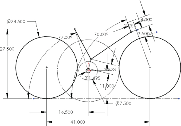
FIGURE 16.3 Adding information to the layout sketch
With this data, you have all the critical point locations to design the actual frame. The first step in creating the frame is to place reference geometry (sketch planes) from which to make sketches for the individual tubes of the frame. The frame will be a carbon fiber monocoque, but it still relies on tubular geometry, with smooth blends between the tubes to reduce stress concentrations. The layout with the planes and the initial tubes is shown in Figure 16.4.
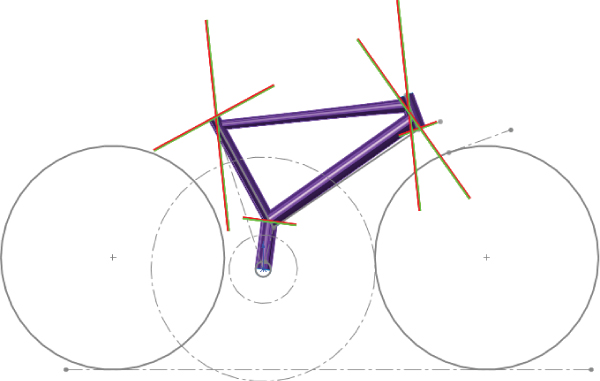
FIGURE 16.4 Building the tubes for the frame
When all the tubes are created in-place in the assembly from the assembly layout sketch, the top of the assembly FeatureManager looks like Figure 16.5.

FIGURE 16.5 Examining the features built from the assembly layout sketch
The arrow symbol (→) indicates that there is an external reference from the part to the assembly sketch. (External references are covered in more detail in Chapter 21, “Editing, Evaluating, and Troubleshooting Assemblies.”) Using the assembly layout sketch technique, an external reference is made every time a relationship is made from the part to the assembly sketch. Many users prefer to avoid external references, mainly because of the file management issues they cause, the difficulty in repairing them when broken, and rebuild speed performance issues. However, references to an assembly sketch are more stable than references between two parts in an assembly.
When you use an assembly layout sketch for either the in-context part building or simply part positioning, the main advantage that it offers is to give you a single driving sketch that enables you to change the size, shape, and position of the parts. You can use as many layout sketches as you want, and you can make them on different sketch planes. This enables you to control parts in all directions.
One of the drawbacks of this technique is that you give up dynamic assembly motion. When you create the parts in the context of the assembly and create relationships between sketches or features and the assembly sketch, you cannot move the parts by just dragging them with the cursor. To move the parts, you must move the sketch and rebuild. The part does not move until the sketch is updated. If you need to combine layout functionality with dynamic assembly motion, you can add more instances of the in-context parts that are mated in the traditional way. However, when using this method, be very careful about which instance you make your edits to, because in-context relations are driven by the original instance.
![]() Another drawback of the assembly-level sketch in general is that you cannot use a sketch picture inside the sketch. Sketch pictures can contain important reference information for building a model. The lack of this capability is certainly noticeable. You can put your sketch picture in a part or even a virtual component.
Another drawback of the assembly-level sketch in general is that you cannot use a sketch picture inside the sketch. Sketch pictures can contain important reference information for building a model. The lack of this capability is certainly noticeable. You can put your sketch picture in a part or even a virtual component.
Using Master Model
The master model technique is covered in depth in Chapter 33, “Employing Master Model Techniques,” but it is mentioned here because it works as an alternative method with the layout idea. The term master model can mean a couple of different things: It could be a single part where multiple bodies are created and then later split into multiple parts. Also, it is sometimes used as the name for inserting a single part with sketches and reference geometry into one or more other parts to have a single reference without creating that reference in the assembly.
This still creates an external reference, but it creates only a single external reference instead of possibly dozens, and updates of the inserted part can be locked. Performance problems with this technique are less serious. Also, if the file management fails and SolidWorks cannot find the inserted part, you can still keep working. SolidWorks keeps enough data in the child part that it does not need to constantly access the parent part.
The master model technique seems to have more advantages and fewer disadvantages than the methods that use assemblies. The dynamic assembly motion problem doesn't exist in a master model arrangement, nor does the lack of sketch picture functionality.
An example of this kind of work is shown in the derailleur assembly in Figure 16.6.
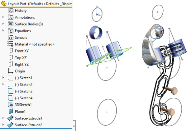
FIGURE 16.6 Using a master model to drive the individual parts of an assembly
The part shown on the left is the master model. Notice that it contains sketch, plane, and surface data. The image on the right shows some parts superimposed on the master model part.
Using the Layout Feature
Due to some quirky behavior, the Layout feature is not generally employed by users. Most people who have been using the layout techniques described earlier in this chapter haven't switched to that method, even though it has replaced older methods in the official SolidWorks assemblies training manuals.
![]() The Layout feature is a 3D sketch that is given special treatment within an assembly. It works best with sketch blocks. These are the special properties of the Layout feature when compared to a 2D assembly sketch:
The Layout feature is a 3D sketch that is given special treatment within an assembly. It works best with sketch blocks. These are the special properties of the Layout feature when compared to a 2D assembly sketch:
- Uses a 3D sketch
- Works best when actively sketching on a plane
- Works best when the sketch making up a part is made into a sketch block
- Enables you to extrude the first feature of a part directly from the sketch block
- Enables sketch relations between blocks to turn into mates
- Permits unlimited dynamic assembly motion—parts move with the motion of blocks in the Layout
To initiate a Layout, click the Layout button on the Layout tab of the assembly CommandManager or activate it from the Insert menu. After you are in a Layout, SolidWorks puts you into a 3D sketch with the Front (XY) plane activated, so it displays a small grid.
For now, you should treat the 3D sketch as much like a set of 2D sketches as possible. The main difference is that you can double-click a different plane to start sketching on the new plane, and you always see this small grid when a plane is active.
You may find that 3D sketches have some limitations when you are working with Layouts. For example, they lack the capabilities to use sketch patterns and sketch pictures.
Using the Layout Workflow
With most functions in software of any type, you tend to get better results when you can use the software in the way it was intended. Generally, developers have a workflow in mind when they design the function itself and the interface. Working with the software is usually easier than working against the software.
Here is the general workflow for using the Layout feature:
- Open a new or existing assembly.
- Click the Layout toolbar button on the Layout tab of the CommandManager.
- Sketch on the plane in the 3D sketch to create 2D sketches representing parts of a mechanism or other assembly.
- Make selections of the sketch into blocks representing individual parts.
- Insert multiple instances of the blocks to represent multiple instances of the parts.
- Use sketch relations to put the blocks together like mating parts in an assembly.
- Test the mechanism by dragging sketches. (Blocks function as a single sketch entity, so you can drag them within the sketch like parts in an assembly.)
- Right-click the block (from inside or outside the Layout), and select Make Part From Block (also a button on the Layout toolbar).
Working with Virtual Components
Virtual components always exist with in-context workflows and frequently with the Layout workflow. Virtual components are parts or subassemblies that are created within the assembly. You can save a virtual component externally, and you can make an externally saved part into a virtual component. The advantages of virtual components are that you don't have to worry about saving out additional files and that the assembly will never lose track of any virtual component.
Some SolidWorks users use virtual components to represent non-geometric parts such as glue or paint. Anytime you choose Insert ➢ Component ➢ New Part from the menus and select a template and a plane to put the part on, the part is placed immediately into the assembly, and you can start working without worrying about having to save the assembly and the part. This saves lots of time initially. Later, when you save the assembly, SolidWorks will prompt you to save the parts externally and name them as well, or you may choose to leave the parts internal to the assembly.
Virtual components are named Part1 Assem1, where Part1 and Assem1 are default names. You can easily rename the part by clicking the RMB menu and selecting Rename Part. You cannot do this for external parts (unless this option is enabled). If you make an external part virtual, the name in the assembly becomes Copy offilename Assem1, where filename is the name of the external file. The name of the assembly is always included (and cannot be removed) to ensure that if you have subassemblies that also have virtual components, you always have unique filenames for all the parts.
Virtual components can also be accessed in their own window, which makes them easier to edit for some purposes. Bills of Materials (BOMs) and numbered balloons work correctly with virtual components, but they cannot have their own drawings.
Balancing Advantages and Limitations
In theory, the Layout feature has several advantages:
- You can make parts from blocks within the Layout.
- You can move parts by moving blocks in the Layout.
- It is a great way to structure your relations within an assembly.
- A single 3D sketch doesn't have the history concerns that multiple 2D sketches have.
- It is useful for motion analysis studies in 2D, using stick sketches, before any 3D components are created.
In practice, this feature needs some enhancements before it is ready for use on real assemblies. Using 2D sketches as assembly layout sketches may still be a better idea than trying to avoid the following limitations of the formal Layout feature:
- The 3D sketch used for Layout has all the limitations that come with 3D sketches.
- Sketch relations are listed in the Mates folder.
- Gaining access to edit the Layout after it has been closed requires a method you don't expect from a sketch: You click the Layout button on the toolbar rather than right-click and edit an icon in the FeatureManager.
- It requires that you use blocks to access all the functionality.
- A fully defined 3D sketch with blocks is very unstable.
- Part creation from blocks doesn't save time.
- You cannot paste copied sketch entities from a 2D sketch into the Layout.
- You cannot use sketch pictures in the Layout.
- You cannot use auto-dimension (or polygons or ellipses) in the Layout.
Although the formal Layout feature has serious advantages over regular layout sketches, at this time, the limitations outweigh the advantages. The rest of the discussion on layouts addresses the generic layout technique rather than the formal feature.
Tutorial: Working with a Layout
In this tutorial, you will use regular assembly sketches to lay out and build a tooling die.
- Open the
Chapter 16 tutorial layout start.sldasmassembly from the download material. Notice that three layout sketches and some of the parts have been added already. The existing parts are virtual components, saved inside the assembly, so there are no referenced part files.  Click Add New Part under the Insert Components dropdown on the Assembly tab. The cursor appears with a green check mark; in the lower-left corner, the taskbar prompts you to select a plane on which to place the Front plane of the part. A sketch automatically opens on that plane. Click the Front plane of the assembly in the FeatureManager.
 Click the Corner Rectangle sketch tool from the Sketch toolbar. Create a rectangle from the two corners indicated in Figure 16.7. It may be helpful to switch to the Front view before drawing.
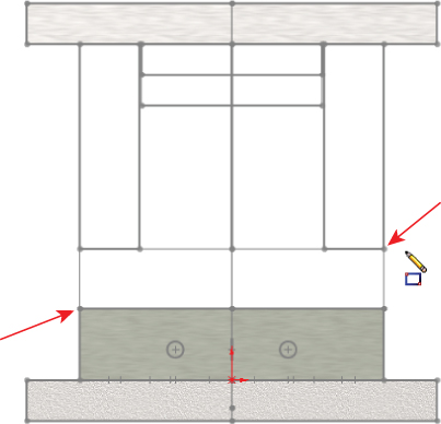
FIGURE 16.7 Creating a new plate in the context of an assembly with layout sketches
 Extrude the rectangle using the Up To Vertex end condition for both Direction 1 and Direction 2. Select sketch endpoints in the Plane Depth Layout sketch for both directions so the new plate matches the other existing plates. You will need to rotate out of the Front view to make these selections. Be careful not to click model faces, edges, or vertices when creating these depth references. Make sure that all your selections are sketch entities, and not solid geometry.
 Click the Exit Edit Part icon in the Confirmation Corner (the upper-right corner of the SolidWorks graphics window). Right-click the new part in the FeatureManager, and select Rename Part. Rename it Plate4. You can also use the Windows standard method of slowly double-clicking (or pressing F2) to rename parts. The “Chapter 16 tutorial layout start” part of the name is automatically added because this is still a virtual part. Assign a material from the Appearances tab for the new plate.
- Follow the procedure outlined in steps 2 through 5 for the four remaining plates, as shown in Figure 16.8. To summarize the steps again, you add the new part, create a sketch, and extrude the block.
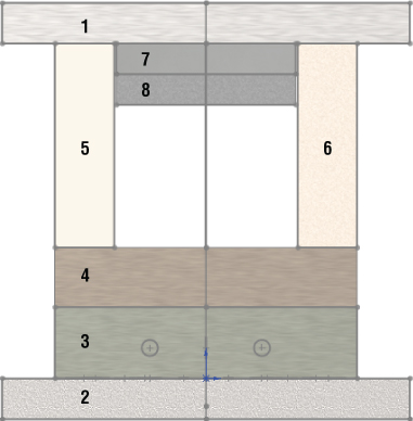
FIGURE 16.8 All the plates controlled by the layout sketches
- Reorient the view to the Top view (Ctrl+5), and make sure you can see the Pin Layout sketch.
 Select the top face of Plate 1, and click the Hole Series toolbar. The Hole Series may be hidden under the Assembly Features flyout on the Assembly tab of the CommandManager.
- Place two sketch points at the centers of the circles, as shown in Figure 16.9. Make sure that the two points are both over the same plate, 5 or 6. You cannot cut both plate 5 and plate 6 in the same Hole Series feature. Use the settings shown in Figure 16.9.
Make sure the holes are Counterbored, ANSI Metric, Socket Head Cap Screw, M10, with a head clearance of 0.10 inch. All other conditions should follow Figure 16.9.

FIGURE 16.9 Placing screw holes through multiple parts in the die
- Place two more new holes on the other side. Make the parts transparent so that you can see how the holes have been placed.
 Create a Plane feature. Make the new plane parallel to the Top plane of the assembly, and coincident to the line indicated in the Plate Depth Layout sketch in Figure 16.10 (best displayed in Right view). Rename the new plane Sprue Bushing Seat.
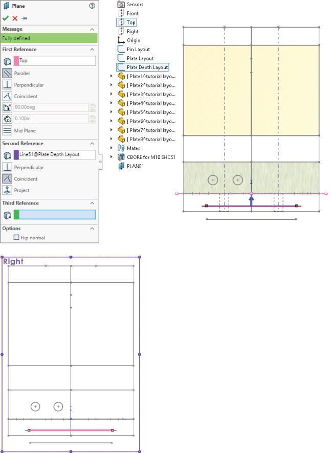
FIGURE 16.10 Creating a plane in the assembly driven by the layout sketch
 Create a new part on the Sprue Bushing Seat plane.
- Activate the Convert Entities sketch tool, select the large (approximately 4-inch diameter) circle from the Pin Layout sketch, and convert it into the sketch plane of the new part.
- Draw a ½-inch circle in the center (at the origin). Extrude the sketch 0.875 inch so it protrudes from Plate 2.
- Exit the Edit Part mode (using the Confirmation Corner). Rename the new part Sprue Bushing.
- Click Plate2, and select Edit Part from the shortcut toolbar.
- Open a new sketch on the Sprue Bushing Seat plane (which is part of the assembly, not part of the part).
- Select the large circle used in step 13, and use the Offset sketch tool to offset the circle 0.005 inch to the outside. Create a Through All cut that comes out the exposed side of Plate2, clearing an area for the Sprue Bushing. You may need to switch to Wireframe display to accomplish this.
- Apply a chamfer to the outer edge of the new cut, 0.010 inch.
- Exit Edit Part mode, and save the assembly to a new folder by choosing File ➢ Save As. Click the Save All button, and then select the Save Externally option, as shown in Figure 16.11.
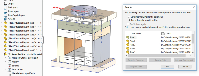
FIGURE 16.11 Saving the internal virtual components to external parts
- Double-click the Plate Layout sketch, and change the 5.836-inch dimension to 6 inches. Change the 7.244-inch dimension to 7 inches. Make sure the model rebuilds, and watch the individual parts update. Figure 16.12 shows these dimensions for reference.

FIGURE 16.12 Editing layout sketch dimensions to drive the size of the individual parts
The Bottom Line
Laying out an assembly with reference sketches is a more disciplined way of working that can help you avoid some of the complications of external references and in-context design work. It is up to you to decide whether the informal 2D layout sketches are preferable to the formal 3D sketch-based Layout feature. Both offer tools to control positions of parts and even features of parts within an assembly.
Traditional assembly-modeling methods where each part is located by mates from another part do not stand up well against changes in the parts themselves. The main goals of the layout methods are centralization of control and stability of changes. I invite you to explore some of these methods using the tools you have learned in this chapter.
- Master It Use an assembly Layout to create a four-bar link and assign parts to the blocks in the Layout sketch. To remind you, the workflow for Layout is like this:
- Open the assembly.
- Click the Layout tool.
- Sketch three bars of differing lengths.
- Create three separate sketch blocks, one using each bar.
- Assemble the bars to create a four-bar link mechanism. (Yes, a four-bar link can have only three bars, the fourth bar is ground.) If you cannot see how to do this in a 3D sketch, refer to the downloaded example for this chapter for hints.
- Test the motion of the assembled link blocks.
- Exit the Layout.
- Create parts on each of the blocks.
- Use the sketches in the parts to create solid geometry for the bars.
- In the assembly, test the motion using dynamic assembly motion (dragging parts).
- Master It Use the assembly you created (or the downloaded example named
4-bar Link Layout solution.sldasm) to first rename and then save out the internal virtual parts so they are external, stand-alone parts. - Master It Edit the Layout from the previous exercise. Change the length of one of the links. This will involve first clicking the Layout tool, and then editing one of the blocks. When you exit the block, the layout sketch and then the solid geometry should both update. Perform a test by exiting the layout and making sure the motion is still correct.