
Chapter 11
Working with Part Configurations
Configurations, also known as simply configs, are variations of a part in which dimensions are changed, features are suppressed (turned off), and other items such as color or custom properties may be controlled. Configurations enable you to have these variations within a single part file, which is both convenient and efficient.
This chapter deals only with part configurations, but assemblies can also have configurations. Assembly configurations can use different part configurations, among other things. This will mean more to you as you learn about part configurations. Assembly configurations are discussed in Chapter 19, “Controlling Assembly Configurations and Display States”.
One example of configurations is having many sizes of a fastener within a single part file. For example, socket-head cap screws can come in thousands of sizes, and you can very efficiently reuse the same sketches and features to create all of those sizes based on a table. Configured parts can also have features that you can turn off and on (suppress and unsuppress, respectively), such as a cross drive or a slotted drive. Changing dimensions and suppressing or unsuppressing features are the most commonly used techniques available through configurations.
There is some overlap between the topics of configurations and display states, with colors and hide/show states being controlled by both methods. When you have the option, always control visual properties using display states, because they require fewer resources, which means they'll be faster. Display states for part documents are covered in more detail in Chapter 5, “Using Visualization Techniques,” and Chapter 19, “Controlling Assembly Configurations and Display States.”
Controlling Items with Configurations
With every new release of SolidWorks software, it seems that more items become “configurable”—that is, able to be driven by configurations. Configurable items for parts include the following:
- Feature dimensions, tolerances, and driving/driven state
- Suppression of features, equations, sketch relations, and feature start and end conditions
- Sketch planes used by a sketch
- Materials
- Configuration-specific custom properties
- Parts, bodies, features, and face colors
- Derived configurations
- Properties that can be assigned, such as mass and center of gravity
- Base or split parts
- Sketch pattern instances
- Sketch text
- Scale feature sizes
- Cosmetic threads
- Equations
- Global variables
- Helix feature parameters
- Size of Hole Wizard holes
You can control configurations in several ways:
- Making changes manually to dimensions and features
- Using the Configure Feature/Modify Configurations table
- Using an Excel-based design table
- Using the Configuration Publisher
Finding Configurations
![]() SolidWorks configurations are listed in the ConfigurationManager. This is a tab at the top of the FeatureManager area, shown in Figure 11.1.
SolidWorks configurations are listed in the ConfigurationManager. This is a tab at the top of the FeatureManager area, shown in Figure 11.1.
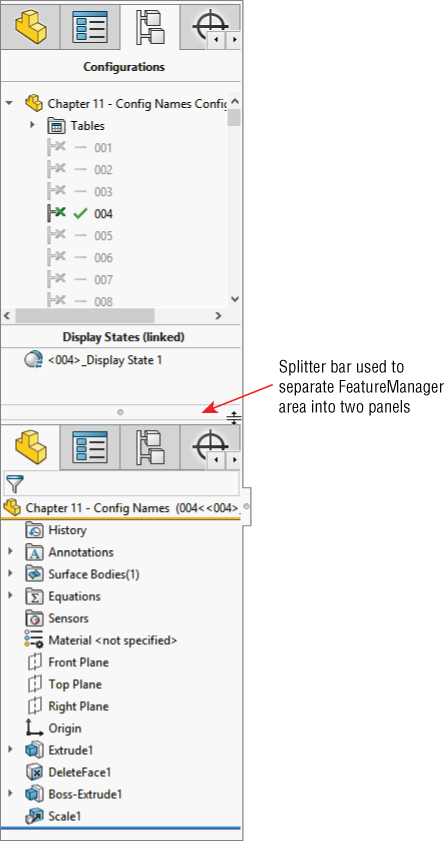
FIGURE 11.1 Locating the ConfigurationManager tab
Deleting Configs
When you're using a standard template, each part has a default config named “Default.” There is nothing special about this config; you can rename it and even delete it. At least one config must always remain in the tree, and you cannot delete the configuration that is currently active. If you want to remove a config, switch to another config (by double-clicking the other configuration in the ConfigurationManager) and then delete the one you want to remove.
If you try to delete a part configuration being used by an open assembly, SolidWorks will simply issue the message “None of the selected entities could be deleted” without explanation.
If you delete a configuration of a part that is used in an assembly, but the assembly is not currently open, the next time the assembly is opened, it will issue the message “The following component configurations could not be found [component configuration name]. If the configuration was renamed the same configuration will be used, otherwise the last active configuration will be substituted for each instance.”
You can delete groups of configs using Windows select tools (Shift+select or Ctrl+select) in the ConfigurationManager. You can also use the right mouse button (RMB) menu, much like regular features in the FeatureManager. None of the configurations selected for deletion may be active or referenced by other open and resolved documents.
Sorting Configs
In the ConfigurationManager, configs can be listed in one of five ways:
- Numeric: Sorts in ascending numeric order
- Literal: Sorts ascending alphabetical order
- Manual: Allows you to determine the order by drag-and-drop
- History-based: Sorts by creation date
- Design Table: Sorts by the order in which they are found in the design table
To control which sorting option is used, right-click on the name of the part in the ConfigurationManager tab and select Tree Order.
ENHANCING ALPHABETIZATION
This alphabetized order is significant because many other sections of the SolidWorks interface are not alphabetized, which causes problems when you are browsing for items in larger lists. Sections that are not alphabetized include Help/Contents, Files Of Type lists in Open and Save dialog boxes, the File Locations settings (Tools ➢ Options ➢ File Locations), Entity Color lists, and several others. If you are inclined to submit an Enhancement Request to SolidWorks, alphabetization of lists is one topic that would benefit everyone and should be easy for SolidWorks to implement.
NAMING CONFIGS
In order for this sorting and alphabetizing to work, you must first properly name the configs. For example, if you have a list of sizes or config names from 1 to 100, then you should use 001, 002 … 100 as your syntax. This makes it easier to browse the config names. Syntax becomes most important when you place a part with many configs into an assembly, because you must select a config from the list, and typing the first few numbers is often faster and easier than scrolling to it.
To understand this technique better, you can open the part called Chapter 11 Config Names.sldprt from the download files, split the FeatureManager area, and change one of the panes to display the ConfigurationManager. Click one of the configuration names and type a number between 001 and 100. The highlight will scroll to the number that you typed. By thoughtfully selecting the configuration names, you can save yourself and your coworkers lots of time when inserting select configs into an assembly.
Activating Configurations
Within a part file, to change the display from one configuration to another, you must first switch to the ConfigurationManager panel, and then either double-click the desired config or right-click it and select Show Configuration.
Alternatively, you can right-click the config in the ConfigurationManager and select Show Preview, as shown in Figure 11.2. A small preview thumbnail will display in the PropertyManager panel. However, not all configurations have previews. For example, in a part with many configs that have been generated automatically by a design table, the configurations may not have previews because the config itself has never actually been rebuilt. Previews exist only when the configuration has been activated at least once, the image on the screen generated, and the part saved. SolidWorks stores both the body (geometry) and the preview image of the part so that next time you access the configuration, the software does not have to rebuild everything again. Storage space is cheaper than rebuild time.
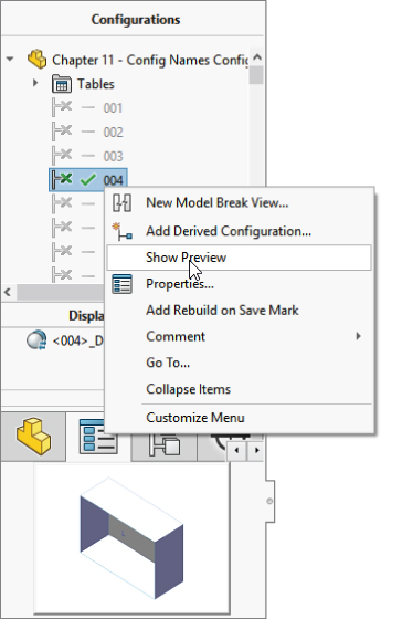
FIGURE 11.2 Showing a configuration preview
You can even select a configuration while opening a file. By doing this, you will save time by not needing to rebuild the model. To take advantage of this option, you must use the File ➢ Open interface, which is shown in Figure 11.3. You can select the config from the lower-left drop-down Configurations list.

FIGURE 11.3 Selecting a configuration from the Open dialog box
Creating Configurations
You can create configs manually using the Modify dialog box, using the Configure Feature/Modify Configurations table (shown in Figure 11.4), or through Excel-driven design tables. Design tables are extremely useful for situations where more than a few configs or more than a few items are being controlled, and as always, the more people who will be working with the data, the more tightly you need to control it. It would be a safe best practice to say that any time you use configurations, and the items being controlled can be handled by a design table, you should use the design table.

FIGURE 11.4 Selecting a configuration from the Modify dialog box
For now, I'm going to focus on creating and manipulating configs manually so you can become familiar with them without also worrying about Excel and design-table syntax. I will talk about design tables near the end of this chapter.
CREATING A NEW CONFIG
To make a new config, you can right-click the top-level icon in the ConfigurationManager, which displays a part symbol and the name of the part, and select Add Configuration. New configurations copy the currently active configuration. If you right-click an existing configuration, SolidWorks makes a derived config, which I will discuss later in this chapter. Figure 11.5 shows the RMB menu and the Properties dialog box that you can use to set up the new config.

FIGURE 11.5 Creating a new configuration
USING CONFIGURATION PROPERTIES AND OPTIONS
The name of the config is important mainly for quick access and organizational purposes. The configuration description is also important, because it can display in the ConfigurationManager and even in the Assembly tree. (You can also use the FeatureManager filter to search configuration descriptions.) This is important when the name of the config is numerical rather than descriptive, and you want to also have a description but not include it in the name. The config description can also appear in place of the filename in the Assembly tree display. Config descriptions can be driven manually through the Configuration Properties dialog box or through a design table if you have very many configs to manage. You can display config descriptions through the RMB menu, as shown in Figure 11.6.

FIGURE 11.6 Enabling configuration descriptions
The Bill Of Materials (BOM) option is set in the Configuration Properties to use the filename, the configuration name, or a custom name that the user specifies. You can save this setting with a template. You achieve control over configurations through the combination of the Configuration Properties and the Advanced Options, which I discuss next.
USING ADVANCED OPTIONS
Three advanced configuration options are found in the bottom panel of the Configuration Properties PropertyManager and are shown in Figure 11.5:
- Suppress New Features And Mates The Suppress option suppresses any new features that are added to other configurations of this part while this option is active. It also suppresses any assembly mates that are added to another active configuration in an assembly. Relying on these options, regardless of the setting, can create problems if you are not using design tables. Manually controlling options in large numbers of configurations can be very error-prone. I personally wish the features and mates options were separated because I like the Suppress Features option to be on, while I would prefer the Suppress Mates option to be off.
- Use Configuration Specific Color Colors are actually driven by display states. Display states in turn can be linked to configurations. If you are driving colors in configured models, you should get into the habit of using display states and just linking them to configurations.
- Add Rebuild On Save Mark When the Add Rebuild On Save Mark option is enabled, the next time your model rebuilds, this configuration will be rebuilt whether it is active or not. Generally, we think of rebuilds as being a good thing, because they keep all the relationships and the geometry up-to-date. But the one problem with rebuilds is that they can take a lot of time. This is especially true if you have a lot of configurations that need to be rebuilt. Be careful how you use this switch. It also can increase the file size. Very often there is a trade-off between options like this and some other variable. You must decide for yourself what is most valuable to you.
USING THE MODIFY DIALOG BOX
The Modify dialog box enables you to change dimensions by just double-clicking the dimension and changing the value. When you change a dimension using the Modify dialog box in a part that has more than one configuration, an additional button, shown in Figure 11.7, appears in the Modify dialog box.

FIGURE 11.7 The Modify dialog box
Modify has three options for configuring dimensions: This Configuration, All Configurations, and Specify Configurations. All Configurations is the default option. Choosing the Specify Configurations option opens a dialog box, which is shown in Figure 11.8.

FIGURE 11.8 Using the Specify Configurations dialog box to change a dimension in multiple configurations
USING NEGATIVE DIMENSIONS
A negative dimension serves only to change the direction of the dimension, and then the negative dimension is discarded; it does not stay with the dimension. An equation that results in a negative dimension flips the sense of the dimension every time it is rebuilt. This may be a useful trick, but in most modeling situations, it’s an annoyance. When you put a negative dimension in a Modify dialog box, the dimension changes sense (direction) and the negative sign disappears after one rebuild. If you put a negative dimension into a Modify Configurations dialog box, it also disappears and changes the direction of the dimension for all configurations. When you enter a negative dimension into a design table, the negative is retained (until the next time you open the design table), and the sense of the dimension is retained only for the configs to which you assigned negative dimension values.
Negative dimensions can be assigned only to sketch dimensions, not to feature dimensions. You cannot change the extrusion direction by making the blind depth negative. Be careful if you use Instant 3D to change the direction of an extrude, because this may change a boss to a cut in addition to making it go in the other direction.
Using the Modify Configurations Dialog Box
The Modify Configurations dialog box, shown in Figure 11.9, enables you to create and modify configured features and dimensions in a more organized way than by using the simple manual methods described earlier, but without getting involved in an Excel-based design table, described later in this chapter. Do not confuse the Modify Configurations dialog box with the Modify dialog box, which is used to change dimensions.
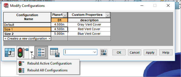
FIGURE 11.9 Using the Modify Configurations dialog box to configure a feature
You can access the Modify Configurations dialog box by right-clicking a dimension or feature you want to drive via configurations and selecting Configure Dimension or Configure Feature.
With the Modify Configurations dialog box active, double-click a dimension to add it to the configured features list. You can add configurations on the fly by typing in the appropriate box, and you can change values or states of features by double-clicking and entering numbers or selecting the check box in the appropriate column (suppressed features will use a check box to define whether the feature is suppressed or not).
I tend to use either the manual or Excel-based techniques. Modify Configurations is valuable for people who want to configure a couple of features without getting involved in a big spreadsheet. It might also be valuable to people who do not have Excel available on their computers but want to create a more structured way to manage configuration data. You can also use it to rename dimensions by following these steps:
- Turn on the Show Feature Dimensions setting in the Annotations folder.
- Select a dimension.
- Use Ctrl+A to select all dimensions.
- Select Configure Dimension from the RMB menu
- Use the Modify Configurations dialog to rename multiple dimensions.
In addition, I should mention that much folklore exists surrounding what is perceived as a problematic relationship between Excel and SolidWorks. Some users claim that Excel often causes SolidWorks to crash. Beyond that, many workplaces may not have Excel available to them, either because of the cost or because they use a non-Microsoft solution for spreadsheet applications. These users still want the functionality of design tables even if Excel is not installed on their machines.
The icons in the lower left of the Modify Configurations dialog box enable you to use the dialog box for more than just dimensions and feature suppression, including custom properties.
The Modify Configurations dialog box does not give you control over everything. Some things, such as part color, Some things that you can configure, such a part color, cannot be driven from this dialog box. Design tables are still the most powerful way to go, but Modify Configurations offers lots of flexibility and immediacy.
USING TABLE VIEWS
![]() The Modify Configurations dialog box adds significantly to your options for creating and editing configurations. Two very nice tools that add to the convenience and power of SolidWorks configurations are called Table Views and Hide/Show Custom Properties.
The Modify Configurations dialog box adds significantly to your options for creating and editing configurations. Two very nice tools that add to the convenience and power of SolidWorks configurations are called Table Views and Hide/Show Custom Properties.
The Table Views tool enables you to keep a small table of only the parameters you want to show. The Parameters drop-down list enables you to select which table view you want to display or to create a new one. Using drop-down lists on the parameter headings, you can suppress the display of any parameter in a new table view.
Dividing what might otherwise be a large design table into several table views helps to keep your data organized and easy to access. Figure 11.10 shows the ConfigurationManager of a part with configurations managed with table views.
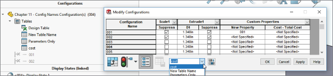
FIGURE 11.10 Displaying table views in the ConfigurationManager of a configured part
ADDING CUSTOM PROPERTIES WITH THE MODIFY CONFIGURATIONS DIALOG BOX
![]() The second nice option in the Modify Configurations dialog box is the Hide/Show Custom Properties option. When this button is depressed, the Modify Configurations dialog box shows columns for existing custom properties, as well as a drop-down list that enables you to add more custom property columns. This makes it very easy to control configuration-specific custom properties within a configured part. You might also try the All Parameters toggle at the bottom of the box to automatically pick up all of the differences between configurations.
The second nice option in the Modify Configurations dialog box is the Hide/Show Custom Properties option. When this button is depressed, the Modify Configurations dialog box shows columns for existing custom properties, as well as a drop-down list that enables you to add more custom property columns. This makes it very easy to control configuration-specific custom properties within a configured part. You might also try the All Parameters toggle at the bottom of the box to automatically pick up all of the differences between configurations.
Using Custom Property Managers
The Property Tab Builder enables an administrator to create special Task pane tabs that are used to control custom properties and configuration-specific custom properties. Configuration-specific custom properties can be controlled through design tables, Custom Property tabs, or the regular SolidWorks configuration-specific custom property interface. Select the method that works best for the way you and your company use the software.
Figure 11.11 shows the Property Tab Builder interface. You can access the Property Tab Builder by clicking the Windows Start button and choosing SolidWorks ➢ SolidWorks Tools from the menu. This is the place where you actually construct the interface that shows up in the Properties tab of the Task pane on the right side of the SolidWorks graphics window.

FIGURE 11.11 Using the Property Tab Builder to construct a Custom Properties tab for the Task pane
Using this type of interface enables the administrator to standardize custom properties values due to spelling or differences in interpretation. The Task Pane interface is easy to use and highly customizable. Notice that you can create regular custom properties or configure custom properties, and that option can be set independently for each property value entered using this interface.
After you create a Property Tab file (called a template), save it to the location indicated at Tools ➢ Options ➢ File Locations ➢ Custom Property Files. If you have only one template for a document type (part, assembly, or drawing), it automatically appears when you display the Custom Properties tab of the Task pane. If you have multiple templates established, the Custom Properties tab lets you choose which one to use. Figure 11.12 shows a Custom Properties tab in use within the SolidWorks Task Pane interface.
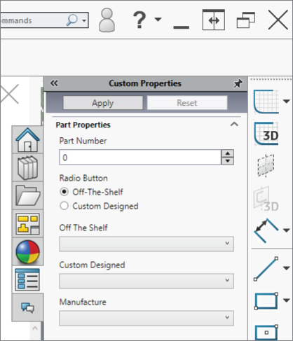
FIGURE 11.12 Using the Custom Properties tab to assign custom properties
Using Derived Configurations
Derived configurations are configs that are dependent on other configs. You can create them from the RMB menu on a configuration, and they appear indented underneath the parent config. Figure 11.13 shows the RMB menu and the position of the derived config in the tree.
![2 Configurations dialog boxes displaying list box with arrow on Add Derived Configuration on highlighted option on the tree. The dialog box on the right also displays list box with highlights on 004 and option 007.05 [007].](http://images-20200215.ebookreading.net/2/1/1/9781119300571/9781119300571__mastering-solidworks__9781119300571__images__c11f013.jpg)
FIGURE 11.13 Creating and placing the derived config
Derived configurations maintain the same values and properties of the parent config unless you break the link to the child (derived) config by explicitly changing a value in the child config. For all other configurable items, the child config value changes when the parent config value changes.
One very nice application of derived configs is to use them for simplified configurations and to set the properties so that any features added to the parent config are also added to the derived config. You can do this by deselecting the Advanced Option Suppress Features (turn it off) in the PropertyManager for the configuration. This causes the derived config to inherit only features that are added to the parent, not to other configs. You can use the simplified configs for Finite Element Analysis (FEA), making drawings of models where all the edge breaks have actually been modeled, or simplified large assemblies. You can also use them for the reverse (a complex config rather than a simple one) to have a config that includes fillets for rendering purposes that are otherwise not used in the manufacturing or documentation processes. In addition, you can create and maintain derived configs using design tables, which are discussed in the next section.
Understanding How File Size Affects Speed
A long-standing dispute has raged over the effects of file size on speed. Here are the facts: When SolidWorks creates a configuration, it can store information about the 3D geometry and a preview thumbnail of the configuration inside the part file. While this is not the default (sometimes only the active configuration data is saved), it can make it faster to access the configuration the next time because it has only to read the stored display data, rather than read parameters and then recalculate new display data. As a result, saving the stored data makes the file larger but also enables you to avoid recalculating.
Many people assign more importance to file size than I do, and they use it as a criterion on which to base decisions about which features or techniques to use or not use. If I have a choice between using a single file instead of multiple files by using configurations, I prefer the single-file technique, even though it is guaranteed to produce larger files—and in some cases, much larger files. This is true especially when the choice is between larger files or longer calculation time. Libraries of parts can often be made more manageable by using configured parts rather than many individual parts. Storage space is cheaper and easier to upgrade than processors. In the end, reading stored data rather than recalculating it is faster, hence cheaper. This is why when SolidWorks can store data that will probably be needed again at some point, it’s a good idea to take advantage of the storage. It is useful to take advantage of the single-file technique. Storage space is cheaper than rebuild time. The result is that configurations definitely increase file size. While SolidWorks never loads all of the data by default, larger files take longer to open, save, move, and perform just about any operation.
Fortunately, SolidWorks can work with very large data sets. There are a couple of options that can tip the balance in your favor between saved data and recalculated data. In the ConfigurationManager, right-click the name of the part and select Add Rebuild On Save Mark. Figure 11.14 shows the options available.

FIGURE 11.14 Purging or saving configuration data
Add Mark For This Configuration means that a Rebuild On Save Mark will be added to the current configuration. The next time the part is saved, that configuration (the active one) will be rebuilt and the data saved.
Add Mark For All Configurations will force the software to rebuild and update all configurations the next time the part is saved. Be aware of the time required for an operation like this. It will vary depending on the complexity of your part (the number of features versus the number of configurations).
Add Mark For Specified Configurations presents you with a dialog box to select which configurations to rebuild and for which to save data.
Remove Mark And Purge Data For All Configurations reduces the size of the file by purging all the configuration data. This is great for file size, but it has an adverse effect on performance when SolidWorks must rebuild configurations.
These four options give you the choice of and control over what is important to you. Figure 11.15 shows what happens when you just right-click on a specific configuration. Notice that some of the configs have a floppy disk symbol. These individual configurations have been marked to be rebuilt and saved. The RMB menu shown reflects that the selected configuration is currently marked with the disk symbol, but it can be unmarked.
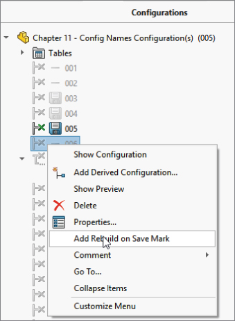
FIGURE 11.15 Marking and unmarking configurations to be rebuilt and saved
To use these options on a larger scale, a new system option purges all cached configuration data. You can find this setting at Tools ➢ Options ➢ Performance ➢ Purge Cached Configuration Data.
Controlling Dimensions
Controlling dimensions with configurations is simple. You need only three things to start: one dimension and two configurations. Because you already know how to create these elements, you are ready to start. Configurations require that you spend some time developing “design intent” for parts. Configurations drive changes in models; if they are properly modeled, you can avoid feature or sketch failures due to dimension changes—or at least you can understand the limits that each dimension needs to remain within.
I will start with the example of a simple block. A fully dimensioned block has three dimensions. Make sure that you have manually created at least two configurations. Double-clicking a model face opens all the dimensions, and double-clicking one of the dimensions opens the familiar Modify dialog box. Figure 11.7 shows that there is a small difference in the Modify dialog box. It now has a drop-down list where you can specify whether this change applies only to this config, to all configs, or to specified configs. If you select specified configs, then a dialog box listing the existing configurations will allow you to select which configurations get the change.
After you're finished, you can toggle back and forth between the configs by double-clicking each of the configs in the ConfigurationManager. Although this is simple, if you forget to change the drop-down list from the All Configurations setting to either the This Configuration or the Specify Configurations setting, you will apply the change to all the configurations. Building a configuration manually is fine for a few simple changes, but it can become unwieldy if you are changing more than a few dimensions or handling only a few configurations in this way. You would then have to remember which dimensions were changed to what in which configurations. As you can see, using design tables is a better method for multiple dimensions.
Controlling Suppression
![]() Suppressing a feature is just like turning it off; the feature appears as grayed-out text in the FeatureManager. With configurations, you can suppress a feature in one config and unsuppress it in another. Also, while a feature may be suppressed, the sketch associated with it is not necessarily suppressed. When you're dealing with manual configuration techniques, there are two methods for controlling suppression: manually suppressing features and creating configurations with the appropriate options for the inclusion of new features, which I discussed previously in this chapter.
Suppressing a feature is just like turning it off; the feature appears as grayed-out text in the FeatureManager. With configurations, you can suppress a feature in one config and unsuppress it in another. Also, while a feature may be suppressed, the sketch associated with it is not necessarily suppressed. When you're dealing with manual configuration techniques, there are two methods for controlling suppression: manually suppressing features and creating configurations with the appropriate options for the inclusion of new features, which I discussed previously in this chapter.
In addition to the Suppress toolbar button, you can also use the Unsuppress and Unsuppress With Dependents functions. When you suppress a feature, any feature that is dependent on it is also suppressed. If you then use the Unsuppress feature, it unsuppresses only the feature itself. However, Unsuppress With Dependents brings back all the dependent features as well.
Generally, SolidWorks users employ a combination of these methods, mainly because configurations are not usually started on a complete model; they are often added when the model is still in progress, so features are added after the users create the configurations.
On the left side of Figure 11.16, you can see a feature that is alternately unsuppressed and suppressed in the tree. The text and icon for the suppressed feature are grayed out. You can suppress features from the RMB menu on the feature, from the Edit menu, or through a tool on a toolbar. The Suppress button is not on a toolbar by default, but you can find it in the Commands dialog box (Tools ➢ Customize ➢ Commands), along with the other buttons for the Features toolbar. Only the Edit menu offers the options of Unsuppress With Dependents and This Configuration, All Configurations, Specify Configurations options for each of the Suppress, Unsuppress, Unsuppress With Dependents functions.
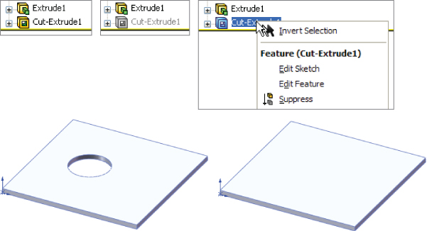
FIGURE 11.16 Suppressing a feature
Using Unsuppress With Dependents can save you lots of time or the hassle of looking for all the features dependent upon a feature that has been suppressed. Because it is not available on the RMB menus, this function is used less than it might otherwise be.
You may also need more control than the use of the simple suppress and unsuppress features. All three options (Suppress, Unsuppress, and Unsuppress With Dependents) have three options: This Configuration, All Configurations, and Specified Configurations. This is a case where the drop-down menu options (Edit ➢ Suppress) offer more detailed functionality than you can find in the RMB menus.
Controlling Custom Properties
Several reasons may compel you to use custom properties, including integration with searches for a Product Data Management system, automatically filling out drawing title blocks, or adding information to the BOM.
When you use custom properties with configurations, you must use the Configuration Specific Custom Properties interface (or an appropriately configured custom property tab or the Modify Configurations dialog box), which enables you to have custom properties that change with each configuration. Standard custom properties apply to the top-level part and keep the same value for all configurations. The configuration-specific functionality is useful for situations such as different part numbers for configurations and many other situations that are limited mostly by your use of configs. The Custom tab of the Summary Information dialog box still applies custom properties that do not change with the configurations to the part.
The interface for managing custom properties manually is shown in Figure 11.17. You can access this dialog box by choosing File ➢ Properties from the menu.
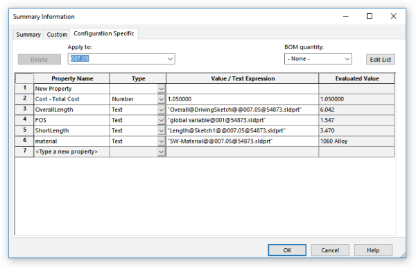
FIGURE 11.17 The Configuration Specific tab in the Summary Information dialog box
You can also link custom properties to mass properties, model dimensions, link values, sketch text, and global variables by selecting from the drop-down list under the Value/Text Expression column, which appears when you select a cell in the column. To link a custom property to a model dimension, simply activate the Value/Text Expression box in the Summary Information interface that you want to populate and click a dimension in the graphics window. Again, managing this data for a single config or only a few configs is easy enough; however, it can quickly become unwieldy, which is where using design tables can make a huge difference.
Controlling Sketch Relations
You can individually suppress or unsuppress sketch relations using configurations. Figure 11.18 shows the Display/Delete Relations PropertyManager interface, at the bottom of which is the Configurations panel. To suppress a relation, select it from the list and select the Suppressed option in the Relations section above the Delete buttons.

FIGURE 11.18 The Display/Delete Relations dialog box for configuring sketch relations
Remember that Display/Delete Relations can be located through the menus at Tools ➢ Relations ➢ Display/Delete, or by double-clicking a sketch relation symbol within a sketch.
Controlling Sketch Planes
You can configure the Offset distance in the From option for extrudes, and you can configure the sketch plane for the sketch that is used in the feature. The Sketch Plane PropertyManager interface expands when configurations are present, as shown in Figure 11.19. To access the Sketch Plane PropertyManager, right-click on a closed sketch and select the Edit Sketch Plane option.

FIGURE 11.19 The Sketch Plane PropertyManager interface for configuring a sketch plane
Controlling Configurations of Inserted Parts
![]() Inserted parts may also be called derived or base parts. However, both of these terms are obsolete. Inserted parts are discussed in detail in Chapter 31, “Modeling Multibodies,” and Chapter 33, “Employing Master Model Techniques”.
Inserted parts may also be called derived or base parts. However, both of these terms are obsolete. Inserted parts are discussed in detail in Chapter 31, “Modeling Multibodies,” and Chapter 33, “Employing Master Model Techniques”.
Inserted parts place the features for one part inside another part. The inserted part becomes a feature in the FeatureManager of the child part. You can insert just the body geometry itself, or you can bring forward reference geometry, sketch data, features, and configuration-specific custom properties and break the link to the original part if you like.
The role of configurations with inserted parts is that the configuration of the inserted part can be controlled from the child component. For example, you may have designed an engine block for an automobile. This engine block is a casting, and using configurations, you have both the six-cylinder and the eight-cylinder blocks in a single-part file. This model represents the “as-cast” engine block. The next step is to make the block with all the secondary machining operations, such as facing mating surfaces, boring cylinders, drilling and tapping holes for threaded connections, and so on. As a result, the as-cast part is inserted into the as-machined part, and the configuration is selected before you add the cut features. As the name suggests, you add inserted parts by choosing Insert ➢ Part from the menu.
The interface for assigning the configuration is shown in Figure 11.20. Simply right-click the inserted part feature, and select List External References. It would seem to make more sense if the configuration could be selected when the part is first inserted, but it does not work this way; you must select the configuration after the part is inserted.

FIGURE 11.20 Assigning the configuration of an inserted part
Using Library Features
Library features can have configurations, and they carry those configurations with them into the part in which they are placed. Unfortunately, part configs cannot reference different library-feature configs. Although library features can be configured, after you drop them into a part and click OK, the configurations will no longer be accessible (unless you have selected Link To Library Part), so a part's configurations cannot select the configuration of a library feature. A part's configurations can change the dimensions of a library feature.
Configurations for library features are created in exactly the same ways that configurations are created for other parts. The technique for saving the configs to the library feature is discussed in Chapter 18, “Using Libraries, Assembly Features, and Hole Wizard.”
Using Design Tables
In addition to describing some of the basic concepts involved with configurations, the first part of this chapter presented reasons for using design tables. For example, while manual configuration management can be haphazard and highly prone to mistakes, design tables lay everything out in an Excel spreadsheet. Although many new users ask whether they can use a different replacement spreadsheet program, you must use Excel for design tables.
Identifying What Can Be Driven by a Design Table
Just because something can be configured does not necessarily mean that it can also be driven by a design table. Here is a small list of items that fit into this category:
- Sketch plane configuration
- Suppressed sketch relations
- Suppressed dimensions (Suppressed dimensions become driven dimensions.)
However, the good news is that many items can be driven by a design table. Table 11.1 lists these items, along with their associated syntax. For the most up-to-date list, check the SolidWorks Help documentation.
TABLE 11.1: Items That Can Be Driven by a Design Table
| ITEM | SYNTAX (GOES IN COLUMN HEADER) | POSSIBLE VALUES (GOES IN FIELD CELL) | DEFAULT VALUE IF FIELD IS BLANK |
| Configs of Inserted Parts | $configuration@<part name> |
<config name> |
not evaluated |
| Configs of Split Parts | $configuration@<split feature name> |
<config name> |
not evaluated |
| Comment Column | $comment |
comment text | blank |
| Configuration Description | $description |
description text | <config name> |
| BOM Part No. | $partnumber |
$d, $document = document name $p, $parent = parent config name $c, $configuration = config name <text>= custom name |
config name |
| Feature Suppression State | $state@<feature name> |
suppressed, sunsuppressed, u |
present suppression state |
| Dimension Value | dimension@<feature name>dimension@<sketch name> |
allowed numerical values | not evaluated |
| Parent Config (creates a derived config) | $parent |
parent config name text | not evaluated |
| Config Specific Custom Property | $prp@<property name> |
property name text | not evaluated |
| Equation State | $state@<equation number>@equations |
suppressed, sunsuppressed, u |
unsuppressed |
| Light Suppression State | $state@<light name> |
suppressed, sunsuppressed, u |
unsuppressed |
| Sketch Relation Suppression | $state@<relation name>@<sketch name> |
suppressed, sunsuppressed, u |
unsuppressed |
| User Notes (same as comment) | $user_notes |
text | blank |
| Part or Feature Color | $color $color@<feature name> |
See SolidWorks Help, Colors, Parameters in design tables. | 0, black |
| Assigned Mass | $sw-mass |
allowed numerical values | value from Mass properties |
| Assigned Center of Gravity X, Y, Z Coordinates | $sw-cog |
allowed numerical values in the format of x, y, z | value from Mass properties |
| Dimension Tolerance | $tolerance@<dimension name> |
See SolidWorks Help, Tolerance Keywords, and Syntax in Design Tables. | none |
Creating a Simple Design Table
When you prepare to create a design table, you generally need to give appropriate names to dimensions, sketches, and features. Remember that although the feature is the most visible item and the easiest to rename, most of the dimensions probably belong to the sketch, which you may also need, or want, to rename. Names should reflect the function or location of the item. It is a good idea to show dimension names when renaming items. (Remember that you can show dimension names by selecting the Dimension Names option by choosing View ➢ Dimension Names.) Figure 11.21 shows the result of renaming the feature and dimension.

FIGURE 11.21 Renamed features and dimensions
You can use one of the following three techniques to add a design table to a SolidWorks part by choosing Insert ➢ Tables ➢ Design Tables from the menus:
- Insert Blank Design Table: This method starts from a blank template that contains the underlying framework, but no values.
- Auto-Create Design Table: This method populates the new design table with any existing configurations and items that are different between the configs.
- From File: This method enables you to create a design table externally and then import it.
Although I prefer the Auto-Create method, it is most appropriate when you have existing configurations. The From File method is best when a design table has been exported from another part, saved externally, and brought into the current part. For the following example, I used the Insert Blank Design Table method.
Figure 11.22 shows the results of starting with the new blank design table. You may notice that the window title bar at the top says SolidWorks, but the toolbars look very much like the Excel interface. This is because Excel is actually running inside of SolidWorks. Clicking outside of the Excel window can cause the Excel window to close; however, there are several items outside of the Excel window that you can select without the window closing, such as features in the FeatureManager and dimensions in the graphics window. You can also rotate and pan the view in the graphics window without closing the Design Table window. If you are very careful, you can also drag the thin hatched border of the Excel window to adjust its size or location.
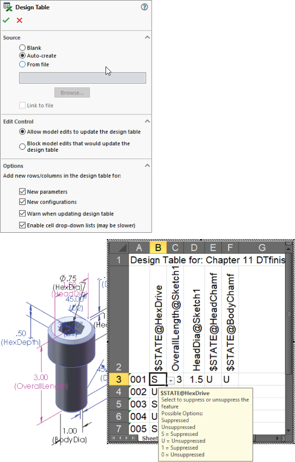
FIGURE 11.22 The interface to create the design table and the resulting blank design table
You can also edit design tables in a separate window, which makes editing easier but makes adding dimension and feature names more difficult. To edit the table in its own window, right-click the design table in the FeatureManager and select Edit Table In New Window.
Figure 11.23 shows a fully developed design table, with some complexity. Although your first design table doesn't need to be this complex, this example demonstrates what you can do with this feature.
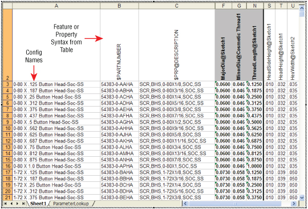
FIGURE 11.23 A fully populated design table
The config names go in the first column, and the feature or property names go in the second row. The first row is reserved for the name of the table. All of this is automatically set up by SolidWorks.
In a new design table, the next step is to type some configuration names. Because you are working in Excel, all the fill functionality is available. To populate the configuration names column, I typed the first three values of 001, 002, and 003, and then window-selected the cells and dragged the fill handle on the selection window to fill the number pattern to populate a larger area. To find more information about this technique, look for “Fill” or “Automatically Number Rows” in the Excel Help files.
The next step is to fill in some feature and dimension names in the second row. The first thing to do is suppress the HexDrive feature. To make this the first feature in the list, click in cell B2 and then double-click the HexDrive feature in the FeatureManager. The name of the feature and its current suppression state are added to the design table with all the necessary syntax and correct spelling.
To rotate the text in this row vertically, right-click row number 2, select Format Cells, click the Alignment tab, and turn the orientation to 90 degrees. The word UNSUPPRESSED displays in all capitals and is fully spelled out, although all you need is a U or an S. Replace the word with an S, and double-click the line between the column heading letters B and C at the top of the Excel window to condense column B as much as possible. Alternate the rest of the rows between Us and Ss to either suppress or unsuppress the HexDrive feature in various configurations. Figure 11.24 shows the current state of the design table.

FIGURE 11.24 Building the design table
Close the Design Table window, and click OK on the message box that lists the new configurations created by the design table. Now split the FeatureManager, set the lower pane to the ConfigurationManager, and double-click some configurations. Notice that in the configs where you specified an S, the HexDrive is suppressed and no longer appears in the model.
You can now add a dimension to the design table. When you're adding a dimension, it is most convenient to display the dimensions on the screen at all times. To show all the dimensions in the part, right-click the Annotations folder in the FeatureManager and select Display Annotations. If the dimensions do not display, you may have to go back and select Show Feature Dimensions. Arrange the dimensions so you can clearly see them all, as shown in Figure 11.25.
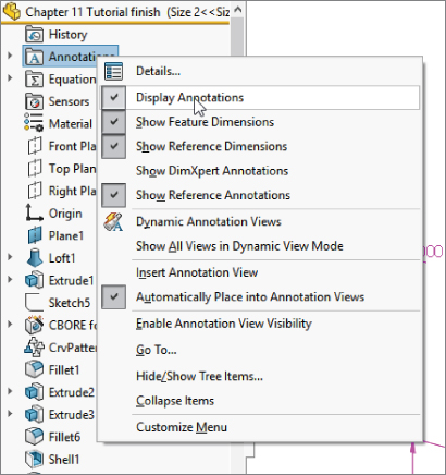
FIGURE 11.25 Dimension and annotation display settings
To display the design table again, locate it in the ConfigurationManager, right-click it, and select Edit Table. Editing the feature changes the settings used for the design table. Edit Table in New Window is an option that you will use later because it simplifies many things; however, for now, using the Edit Table option is the easy way to add new items to the design table.
If the design table displays on top of your model, you can either move the model or move the design table. Moving the design table is a bit tricky and involves dragging the striped-line border of the Excel window; remember not to grab it at the corners or midpoints, because this simply resizes it. If you click inside the border, nothing will happen. If you click outside of the border, the Excel window will close. Moving the model may be easier. To do this, Ctrl+drag in a blank space in the graphics window; it will pan the display so you can see the part dimensions.
With cell C2 selected, or whatever the next available cell is in the second row, double-click the OverallLength dimension in the graphics window. SolidWorks will add the proper syntax to the design table, along with the current value for the first configuration in the list. Fill in values for the rest of the configurations. Now you can calculate these values in Excel using any of the available techniques.
Exit the design table, and toggle through the various configurations to see their different lengths. These examples should get you started on more complex configurations and design tables. Any dimensions that are controlled by the design table (and therefore locked) display in pink on the screen.
A row with special function can be added between the second and third rows. This row can be used to identify column headings with user-assigned names. If you use this method, you may want to hide the second row. The second row cannot be deleted.
Editing Design Table Settings
Figure 11.22 shows the PropertyManager for design tables. After you have created the table, you can edit the table settings by right-clicking the table and selecting Edit Feature. Edit Feature enables you to edit the settings for the table only; it does not enable you to edit values within the table.
- Linked Design Table By selecting the From File source option, you can create a design table from an external file; you can also link the table to the external file. When you use the other two options, Blank and Auto-Create, SolidWorks stores the Excel file within the SolidWorks document. Linking to an external file may be useful if you have a non-SolidWorks user who is entering data into the design table or if a single table controls multiple parts.
- Edit Control The Edit Control panel has two options, which act as a toggle. The Allow Model Edits To Update The Design Table option is self-explanatory, as is its opposite, the Block Model Edits That Would Update The Design Table option. If the Allow Model Edits option is selected and you make a manual change to the model, the next time you open the design table, SolidWorks will warn you about the change and that it will update the design table. Likewise, if you try to make a manual change and the Block Model Edits option is selected, you will receive a warning that the value cannot be changed.
- Options The Options settings determine the behavior when you are using the Allow Model Edits option and a new item has been configured. For example, the design table may already exist, and you manually add a configuration and suppress a feature.
Configurations that have been added manually are displayed somewhat differently from configs that are being managed by the design table. Figure 11.26 shows the two configurations at the bottom of the tree with square symbols, while the design table configs have X (Excel) symbols.
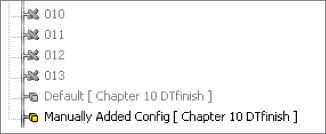
FIGURE 11.26 Manually created configs versus design-table-created configs
After you manually add the config and suppress the feature, the next time you open the design table, the Add Rows And Columns dialog box appears. Many users are simply annoyed by this, but that may be because they don't understand what it does or why it appears. In the example shown in Figure 11.27, a new configuration has been manually added; it appears in the Configurations box as ManuallyAddedConfig, and in the Parameters box, it looks like a feature named BodyChamfer has been either suppressed or unsuppressed manually. The appearance of this dialog box means that SolidWorks is asking if you want to include these items in the design table. If so, simply select the items you want to add to the design table and click OK. If you do not want to include the items in the design table, simply click OK or Cancel. If you click OK, you will not be offered these choices again; if you click Cancel, the next time you open the table, the dialog box with the same choices will reappear. If you never want to see this dialog box again, make sure that all the options in the Options panel shown in Figure 11.22 are deselected.
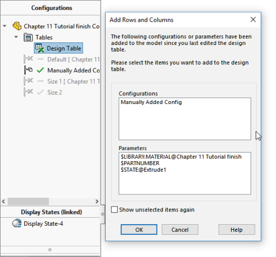
FIGURE 11.27 The Add Rows And Columns dialog box
Editing the Design Table
As I mentioned earlier, working with a design table opened inside the SolidWorks window can sometimes be difficult. One way to handle this problem is to edit the design table inside SolidWorks only when you want to add new features to the column headers; when adding new configurations or editing the field values, edit the table in a separate window. This option appears on the RMB menu as Edit Table In New Window. It gives you much more flexibility in resizing the Excel window, changing the zoom scale, and other operations, but it doesn't enable you to double-click a dimension so it is added automatically to the column header.
Using the Configuration Publisher
The Configuration Publisher enables you to create an interface that creates configurations on the fly based on rules that you establish. The interface that you create appears when you put the part into an assembly, enabling you to create a custom size and a new configuration to go with it. This is similar to putting a Toolbox part into an assembly and getting a special interface to specify sizes and create new configurations if necessary. In order to create a Configuration Publisher for a part, the part must contain a design table with at least a single row. You can use an auto-created design table if needed.
You access the Configuration Publisher by right-clicking the name of the part at the top line of the ConfigurationManager and selecting Configuration Publisher from the menu.
Figure 11.28 shows the Configuration Publisher interface. It is like the Property Tab Builder in that you use it to place interface controls on a PropertyManager that will pop up when the part is placed into an assembly.

FIGURE 11.28 The Configuration Publisher helps you build an interface to create configurations as you place a part into an assembly.
Aside from users putting parts into assemblies, the interface you create using the Configuration Publisher can also be used in 3D Content Central to specify a new component size. If you are a supplier and make parts in a wide variety of sizes, instead of creating all the sizes and uploading to 3D Content Central, you can just create the rules in the Configuration Publisher interface and allow the configurations to be created automatically according to the rules.
When the interface has been created, a PropertyManager entry will show up under the name of the part in the ConfigurationManager, as shown in Figure 11.29.

FIGURE 11.29 The PropertyManager entry in the ConfigurationManager
When the part is placed into an assembly, the PropertyManager, which is the one created in the Configuration Publisher, will appear and enable you to access options to size and configure the new instance. A similar interface is also used if you have uploaded the part to 3D Content Central to allow other people to download the part.
Tutorial: Working with Configurations and Design Tables
Throughout this book, the parts that I use for one purpose may also be useful for other purposes. For example, the part used in this tutorial uses a loft with guide curves where both guide curves are created in the same sketch. The guide curve sketch is made from symmetrical splines where I have used the spline handles to change the shape smoothly and in a controlled way. I have also used a curve-driven pattern to go around an elliptical shape. This demonstrates that configurations can be applied to different types of parts, and some of the more loosely defined shape tools are often used in parts where cosmetic issues are not a design concern.
To start working with configurations and design tables, follow these steps:
- From the download materials for this chapter, open the part called
Chapter 11 Tutorial start.sldprt. Take a moment to become familiar with this part by using the rollback bar and then editing each feature in turn to see how it was made. In particular, look at the two patterns, which must be parametrically linked. Figure 11.30 shows the part.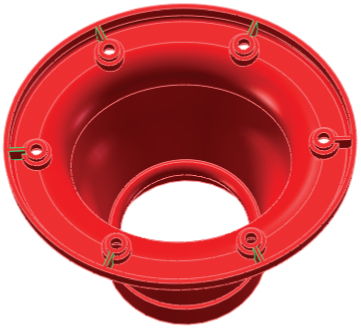
FIGURE 11.30 The
Chapter 11 Tutorial start.sldprtfile - Manually create a configuration for the part called Size 1. Remember that to create a configuration, you must show the ConfigurationManager tab in the FeatureManager area and right-click the name of the part at the top level. Do this by splitting the FeatureManager window and setting the lower pane to the ConfigurationManager.
- Set the Advanced option by selecting both Suppress Features and Use Configuration Specific Color.
- Before closing the Add Configuration PropertyManager, click the Color button on the Advanced Options panel of the Configuration PropertyManager and select a different color for the Size 1 configuration. The color doesn't change immediately. It will change after you close the PropertyManager.
- Choose View ➢ Dimension Names.
- Double-click the feature CrvPattern1 in the FeatureManager. A numeral 6 with a D1 under it appears on one of the holes in the pattern. If you have changed your part to a blue color, it may be difficult to see because the text is also blue.
- Change the name of the dimension to Hole# by clicking the dimension and using the PropertyManager.
- Change the value of the number to 8, and also change the drop-down setting to This Configuration Only instead of All Configurations. If you forget to do this, you must go to the other configuration and set it back to 6.
- Click the Rebuild symbol (which resembles a traffic light) to show the changes before exiting the Modify dialog box. Notice that the CrvPattern2 fails after rebuilding CrvPattern1 with eight instances. Click the green checkmark icon to exit the Modify dialog box, and then make the same changes to the CrvPattern2: change the dimension name and the number of patterned instances to 8 (remember to use the This Configuration Only setting). The part should look like Figure 11.31.

FIGURE 11.31 The model after step 9
- When you double-click to change configurations, the SolidWorks interface displays a part with a different color and a different number of holes and ribs. After the first change between configurations, the changes should happen quickly because SolidWorks has stored the geometry.
- Choose File ➢ Properties and select the Configuration Specific tab. Set the Apply To drop-down list to Default, and type a Property Name of description and a Value of Gray Vent Cover. Now change the Apply To drop-down setting to Size 1, and type a description for the new configuration using the name of the color that you applied to this config.
- Exit the Custom Properties dialog box. Now that you have made a few changes manually, the following steps will guide you through bringing these changes into a design table and using the design table to make additional changes.
- Choose Insert ➢ Tables ➢ Design Table from the menus. Use Auto-Create as the Source, allow model edits, and select all three options in the Option panel. Click OK to create the design table. Figure 11.32 shows the design table you automatically created.
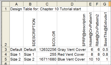
FIGURE 11.32 The automatically created design table
- Use the striped border to move the window without closing it. This may take some practice. If the window closes, right-click the design table in the FeatureManager and select Edit Table. Move the window to a place where you can see the model clearly.
- If a cell in the second row of the design table is selected, select a different empty cell that is not in the second row (this prevents data from automatically populating cells until you have the correct data). Now double-click the Extrude1 feature in the FeatureManager. Find the 0.500″(D1) dimension on the screen. Right-click the dimension, and rename it BaseThk.
- Click the next open cell in the second row, and double-click the 0.500″ dimension that you just renamed. You may have to use the handles at the corners and side midpoints to resize the Excel window to see everything. Add another configuration row and the additional values in the cells, as shown in Figure 11.32. The color number is determined by a formula that you can find in the help section under the topic Color Parameter.
- Remember that this part must have the number of ribs always equal to the number of holes. This is simple to do in Excel. Click in the first row value for the Rib# number. (This is cell F3 in Figure 11.32.) Type the equal sign, and then click in the cell to the left, E3. You can also simply type =E3 in this cell. This links the Rib# cell to the Hole# cell.
- Use the Window Fill feature by selecting the dot at the lower-right corner of the selected F3 cell and dragging it down to include cells F4 and F5, as shown in Figure 11.33.
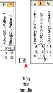
FIGURE 11.33 Copying the equation to other cells
- Click in a blank space to exit the design table. Double-click through the configurations in the ConfigurationManager to see the results of your efforts.
The Bottom Line
Configurations are a powerful way to control variations of a design within a single part file. Many aspects of a part can be configured, although a few cannot. Manually created configurations are useful for making a small number of variations and a small number of configurations, but they become unwieldy when you need to make more than a few variations of either type.
Using design tables to control design variations is recommended because you will be able to see more clearly all the changes you have made to all the configurations. Additionally, by having the power of Excel available, you will be able to access many functions that are not shown here, such as using lookup tables and Concatenate functions to build descriptions or configuration names.
- Master It Create a simple block from a fully dimensioned sketch, name all of the dimensions, and create three configurations such that each configuration changes one of the dimensions. Show all the dimensions on the screen.
- Master It Take the part from the previous exercise and auto-create a design table, add 10 more configurations, with different dimensions in each, and configure a custom property called Vendor to have a different value in each configuration.
- Master It Take the part from the previous exercise and add a feature to it. Use the design table to turn the feature on or off (unsuppressed or suppressed) in each configuration. Also change the part color in several configurations.