
Chapter 20
Modeling in Context
This chapter provides the information you need to make informed decisions about whether or not to use and how to use this powerful tool. In-context modeling is a topic worthy of some investigation before you combine production data with external references. Almost anything you can do with in-context modeling can also be done another way, but in-context is the traditional way of using the geometry of one part to drive another.
In-context modeling extends parametric design from individual parts to top-level assemblies. With this power comes the potential for unexpected results. If you are not careful, in-context modeling can lead to difficulties with file management and loss of control over changes.
Understanding In-Context Modeling
In-context modeling is also known as top-down or in-place modeling. This technique is used to create relationships between parts in the context of an assembly in which the geometry of one of the parts is controlled by both the other part and the mates that position them relative to one another. In contrast, bottom-up modeling involves making the parts in their own individual windows and assembling the finished parts into an assembly with mates.
In its simplest form, in-context modeling involves a sketch in one part in an assembly that is related to an edge in another part in the assembly. The relationship is specific to that particular assembly and is relevant only in the context of that assembly. For example, you may create a box and put it into an assembly. You must then create a lid that is parametrically linked to the size and shape of the box. You can create a lid part in the context of the assembly such that the lid always matches the box regardless of how the box changes. Sketch relationships, dimensions, and feature end conditions from the lid can reference the box. This in-context relationship is also known as an external relationship, where one part has a relationship to something external to itself. When the box changes, the lid also changes if the assembly and both parts are open. This arrangement creates another type of parent/child relationship, where the box is the parent (driving), the lid is the child (driven), and the assembly is the context. As you can see, getting used to the terminology will be one of the first hurdles. As you begin to use the techniques, you will understand why the relationship metaphors make sense.
The assembly maintains a record of each in-context reference. If the box is changed with both the assembly and the top open, then the top updates, but if the box is changed without the assembly being open, then the lid won't update until the assembly is opened. The record of the reference that the assembly maintains is held in what is called an update holder. SolidWorks has arranged things such that the update holder is all but forgotten and difficult to find. One update holder is created for every sketch or feature that contains references to other entities within that particular assembly. To show update holders, right-click the top-level assembly name in the FeatureManager and select Show Update Holders.
Working Through a Simple In-Context Example
Rather than continuing to discuss this topic theoretically, I'll demonstrate some in-context modeling situations, starting with a simple rectangular block. This example starts with a simple rectangular block. You have multiple options to get an in-context part into an assembly, but this example demonstrates just one. The following steps are general, because you should already be familiar with the basics of assemblies and part modeling.
STARTING A NEW ASSEMBLY
Open a new assembly, using the template of your choice. When modeling in-context, it's especially important that the parts and the assembly use the same units. If the assembly units are different from the part units, and you edit the part in the context of the assembly, then you may be presented with one type of unit while editing the part in the assembly and another type of unit while editing the part in its own window.
The next step is to save the assembly. SolidWorks doesn't force you to save it before adding the part, but it's a good idea to save the assembly (and any file, actually) after creating it.
INSERTING A NEW PART
To insert a new part in the new assembly, choose Insert ➢ Component ➢ New Part and select the toolbar icon for New Part from the Insert Component flyout toolbar.
![]() After you click the New Part command, SolidWorks will add the new part to the FeatureManager of the new assembly. Note the default naming convention shown in Figure 20.1. Also, note the cursor with the green check mark on it. This check mark tells you (in conjunction with the text in the message bar at the bottom of the screen) that you need to select a plane or planar face to place the Front (or first, or XY) plane on the Front plane of the assembly. Remember that every template may have the standard planes renamed to anything you choose, so the first standard plane may not be called the Front plane.
After you click the New Part command, SolidWorks will add the new part to the FeatureManager of the new assembly. Note the default naming convention shown in Figure 20.1. Also, note the cursor with the green check mark on it. This check mark tells you (in conjunction with the text in the message bar at the bottom of the screen) that you need to select a plane or planar face to place the Front (or first, or XY) plane on the Front plane of the assembly. Remember that every template may have the standard planes renamed to anything you choose, so the first standard plane may not be called the Front plane.

FIGURE 20.1 Inserting a new blank part into a new assembly
When you click the cursor with the green check mark on a plane or planar face, the Front plane of the part becomes fixed to the Front plane of the assembly, with the origins of the two files aligned, and SolidWorks automatically opens a new sketch on the Front plane of the part. The part name also turns blue. This color means that you are editing the part in the context of the assembly. Whatever you do in this state changes the part document rather than the assembly document. A new sketch, for example, is added to the part rather than the assembly.
INTRODUCING VIRTUAL COMPONENTS
The part you have just added to the new assembly is called a virtual component. It is called “virtual” because the part is not saved yet; it's still just inside the assembly. This is why the name appears as shown in Figure 20.1. When you save the part to an external file, it loses the part of the name that's associated with the current assembly. The “components” part of the name means that both parts and subassemblies can be virtual or they can exist only within the top-level assembly. You will find more information on virtual components later in this chapter.
If you want to save the part to an external file by default, SolidWorks has an option for that. You can find the option at Tools ➢ Options ➢ Assemblies ➢ Save New Components To External Files. Without this setting, you will get a reminder to save virtual parts external to the assembly the next time you save the assembly, unless you have clicked the Do Not Show Again option for that reminder. You can get the reminder back by going to Tools ➢ Options ➢ Messages/Errors/Warnings and deleting it from the list. If you have difficulty keeping track of all these options, the SolidWorks search bar allows you to search options, or you can use the search bar inside the Tools ➢ Options dialog box.
CREATING THE PART GEOMETRY
Sketch a centered rectangle from the origin, and give it dimensions of 4 inches (100 mm) tall by 5 inches (125 mm) wide. Extrude it 2 inches (50 mm). You can find the Extrude Command icon on the Assembly toolbar when editing a part in the context of the assembly.
Now exit the part. To do this, click the Edit Component icon in one of the places where it shows up on the screen. Figure 20.2 shows it in the Confirmation Corner in the upper-right corner of the graphics window. You can also find it on the Assembly toolbar.

FIGURE 20.2 Using the Confirmation Corner to exit Edit Component mode
UNDERSTANDING IN-CONTEXT
You have to be really careful about what you do in the context of an assembly. For example, when you sketched your rectangle in-context, did you make any references that went outside of the part? Of course not, how could you? There is nothing outside the part. Are you sure about that?
The tell-tale sign of an in-context relation is the arrow symbol (->) after a sketch, feature, or part in the FeatureManager. Look to see if you have a symbol like that after your sketch. You probably do. If you have this in-context symbol and haven't saved your assembly, you're primed to fall into the “multiple contexts” trap mentioned earlier. Here's how
First, your centerpoint of the rectangle has probably referenced the assembly origin rather than the part origin. This qualifies as an external reference; therefore, it gets an arrow symbol (->). You could get another one by sketching on an assembly plane instead of the part plane. I told you, you have to be careful in assemblies.
To see these relationships in more detail, while editing the assembly (not the part), right-click on the top-level assembly name in the FeatureManager and select Show Update Holders. Figure 20.3 shows an update holder at the bottom of the new assembly tree, along with the arrow symbol (->) after the sketch.

FIGURE 20.3 Update holders indicate in-context relations.
If you've created this situation, it's easy enough to repair. Edit the sketch, delete the relation between the sketch point and the assembly origin, and re-create it to the part origin. As a hint, select items from the FeatureManager (or from the Select Other dialog) when you're unsure about what the cursor is selecting when multiple items are stacked on top of one another.
SAVING A VIRTUAL COMPONENT
Next, right-click the name of the part you just added and select Save Part (in External File), as shown in Figure 20.4. Give the part the name Box (by slowly double-clicking the default name in the Save As dialog box that appears), and save it to your desktop (by clicking the Specify Path button in the Save As dialog box) or another place where it will be easy to find and delete later. This part is just for practice in this chapter.
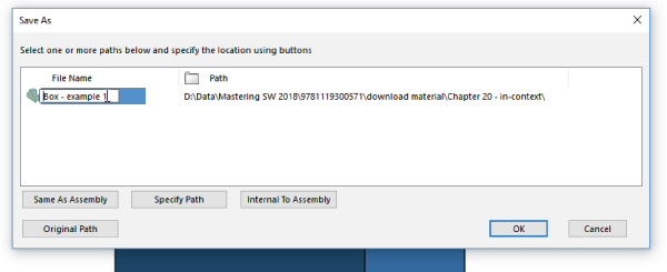
FIGURE 20.4 Saving the virtual components to an external file
Notice that the name of the part in the assembly FeatureManager has changed, and the name is no longer surrounded by brackets or followed by the assembly name.
CREATING AN IN-CONTEXT PART
To create another new part in the assembly, and use the first part to drive this one, you must again click the New Part icon. When you see the cursor with the green check mark, click the 5 × 4 end face that you created using the Extrude feature.
When you do this, the first part you created turns transparent. This helps you identify which part is being worked on (the nontransparent part is current). You can find the settings controlling this behavior at Tools ➢ Options ➢ Colors. Toward the bottom of that page is a setting called Use Specified Colors When Editing Parts In Assemblies. You can find a related setting at Tools ➢ Options ➢ Display. Under the heading for Assembly Transparency For In Context Edit is a drop-down list with three options: Opaque Assembly, Maintain Assembly Transparency, and Force Assembly Transparency. The default is Force Assembly Transparency. These options are shown in Figure 20.5.

FIGURE 20.5 Establishing assembly transparency while editing in-context parts
To create the sketch for the first feature of the in-context part, click the same face that you just clicked to place the second part, and use the Offset Entities to make a sketch loop offset by 0.25 inch (5 mm) to the outside.
To contrast two methods of selection, after using the face selection to offset to the outside, right-click one of the edges of the face of the Box part and choose Select Loop from the menu. A small yellow arrow will indicate the side to which the offset will be created. Then use the Offset Entities to offset sketch lines from the selected loop of edges toward the inside again by 0.25 inch (5 mm). Figure 20.6 shows the result of the offset.

FIGURE 20.6 Using two methods to offset sketches in context
With this single sketch containing a nested loop, use the Extrude feature to extrude 0.5 inch (10 mm). When complete, use the Confirmation Corner again to exit the part. You should now have an assembly that is not saved, a part that is saved with the name Box, and a second part that is just a virtual component.
After exiting Edit Component mode, you should also see that the two parts are the same color. Click a face of the newly created part, click the Appearance drop-down menu, and select the indicator for the part. Figure 20.7 shows the cursor pointing to this indicator. Change the part color using the panel that appears in the PropertyManager (don't change the entire appearance, just the color).

FIGURE 20.7 Changing the color of a virtual component
Another thing to notice about the creation of an in-context part is that SolidWorks adds InPlace mates to the Mates folder that lock the new part in place. Motion can cause in-context features to move unexpectedly, so parts that have in-context features are usually recommended to be locked down in one way or another. This is one way that SolidWorks is looking out for you in the in-context scheme. Figure 20.8 shows InPlace mates and update holders.

FIGURE 20.8 SolidWorks creates InPlace mates for parts started in the assembly and update holders for in-context features.
EDITING THE DRIVING PART OF AN IN-CONTEXT REFERENCE
Now comes the tricky part. You are going to change the overall shape of the Box part and observe the effect on the virtual component. In order to do this, click the sketch under the Extrude feature in the Box part and select Edit Sketch from the pop-up toolbar.
After this is complete, you will be ready to edit the sketch of the Extrude feature in the Box part. If necessary, expand the Box part in the FeatureManager by clicking the plus symbol (+) to the left of the name and clicking the plus symbol next to the Extrude feature. Now you can click the sketch and select Edit Sketch from the pop-up list.
While editing the sketch of the box, right-click one line of the rectangle and choose Select Chain. With all four lines selected, click the Construction Geometry toggle in the PropertyManager. This turns all lines of the rectangle into construction lines.
Next, draw a circle concentric with the origin, with the circumference on one corner of the rectangle. The sketch now looks like Figure 20.9.

FIGURE 20.9 Replacing a rectangle with a circle
After you make this change, exit the sketch. The in-context references won't update until you exit the part and return to the assembly.
Just to get you prepared, what do you expect to see? Remember that one set of referenced edges was referenced by selecting a face, and the other set was referenced by selecting edges.
When you leave Edit Part mode and return to Edit Assembly mode, you'll find that the outer lines have updated to the circle (because the face you selected is circular instead of rectangular), but the edges you selected will still be rectangular and display a warning symbol. This is because the edges referenced by those lines no longer exist. If you hover your cursor over one of the errors shown in Figure 20.10, the message “Warning: Unable to offset one or more sketch entities” will appear. You can avoid this error by using the same technique to select the inner lines as the outer lines (or just using the outer lines and making a Thin feature).

FIGURE 20.10 Responding to warnings when they occur
Go ahead and fix this error by editing the sketch in the Virtual Part (box lid), deleting the lines causing the problem, and remaking them by offsetting from the selected face. Offset sketch relations cannot be repaired or edited in the way you need to repair the existing relations. In general, you should avoid using Delete as an editing technique, but there's no other way in SolidWorks to repair this kind of issue.
This demonstration points out some of the strengths and weaknesses of in-context modeling, but not all of them. The rest of the chapter will help you get a better idea of how to evaluate this technique for yourself.
Weighing the Advantages of In-Context Modeling
The advantages of in-context modeling are obvious. In-context modeling is just an extension of parametric techniques to include parts in the context of an assembly. Making a change to one part and having all related parts update offers indisputable advantages. When it works correctly, all the parts of an assembly can be updated from a single change. Changes propagate all the way through to the part drawings.
Some users approach modeling haphazardly—and if it works, it's “good enough.” For some types of work, this is acceptable and really may be good enough. For example, it usually works when you create something that will never be changed or if you are working on initial concept models that won't be given to other users.
On the other hand, users who need to build models that will be reused frequently, changed often, or given to other users to work on must approach the decisions they make during modeling as if they were playing chess. Each decision has consequences. You rarely know exactly how things are going to turn out, but you need to prepare for the most likely contingencies, assessing potential risks along the way.
Anticipating Problems with In-Context Modeling
The overall concept of in-context modeling is a great idea; the problems occur with the practical application of the technique and the management of the results through changes. In particular, the biggest problems seem to arise when in-context techniques are combined with other techniques. You must be very careful about things such as file management, assembly motion, multiple instances of parts in assemblies, configurations, and related issues when in-context references exist in your assembly.
Major potential problems include the following:
- Lost references due to renamed parts or assemblies
- Convoluted (multiple) references causing long rebuild times
- Circular (self-referring) references causing changes with each rebuild
- External references causing conflicts with motion
- Serious difficulties between in-context techniques and configurations
- Frustrated users who don't understand how to manage changes or references in an in-context scheme
For users who prefer to use model items in drawings, in-context techniques offer some challenges. Model items are either unavailable or limited in availability for features created in-context. This is because if you have used Convert Entities to copy edges of one part to another, no dimensions have been used, so none will show up in inserted model items. In-context model items would show up when you use offset edges or dimension sketch elements to in-context edges. Aside from these, the only model item drawings you can create are in an assembly drawing. For this reason, the majority of dimensions on drawings are driven dimensions.
Identifying Alternatives to In-Context Modeling
One of the most frequent problems with in-context modeling is related to file management. Inexperienced users may move or rename a file or a folder in Windows Explorer and unknowingly break links, or they may try to use an in-context part in some assembly other than where the in-context relation was created. As a result, they may not be able to make changes that they want to make, or changes may happen when they do not want them.
Sometimes these problems are the result of users simply not understanding what to expect from the tool, and sometimes it is because the tool is not capable of doing what they want. Right or wrong, many users have developed an irrational fear of references that can control a part from outside of the part. In-context modeling in itself is not a bad technique, but sometimes it is not the best option, depending on the particular situation. You need to understand in-context and all related techniques first before passing judgment on any of the techniques.
It's always important to identify alternative techniques because one tool never solves all possible problems. In-context modeling is powerful, but in some situations, other techniques are more appropriate. The following sections introduce a couple of techniques that share with in-context the ability to control individual parts from a centralized location, but they achieve that in ways that are somewhat different: assembly layout and multibody modeling. Assembly layout modeling enables you to control individual parts not from other parts but from an assembly-level sketch. Multibody modeling enables you to control several parts from a single part without worrying about the file management issues of having another assembly as the middle agent.
USING ASSEMBLY LAYOUT MODELING
Assembly layouts are powerful tools that remove much of what some people object to in in-context modeling. Relationships in this technique are controlled by top-level sketches, where a single sketch or multiple sketches can control most of the features on all parts through relationships between part sketches or features and the assembly sketch. This still creates an external reference that requires the existence of an assembly to update the relationships, but it is not a direct link between different parts in the context of the assembly.
Assembly layouts do not lend themselves well to dynamic assembly motion, but they are great if you want to have a single location to drive an entire assembly. Assembly layouts come in two types: the generic layout, which is simply done using sketches in an assembly; and the formal Layout feature, which is essentially a 3D sketch in the assembly with special properties. The Layout feature is described in more detail later in this chapter. Assembly layout sketches are covered in more detail in Chapter 3, “Working with Sketches and Reference Geometry.”
USING MULTIBODY MODELING
Multibody modeling, like in-context modeling, is a powerful technique with strengths and weaknesses. If you model something that later will be separate parts together in a single part, you can avoid in-context modeling altogether. You should not replace assemblies with multibody modeling for a number of reasons, such as limitations of multibody techniques for common assembly operations such as dynamic assembly motion and interference detection. Used judiciously, multibody modeling can help you save time making models that hold up well to changes. Master model techniques are discussed at length in Chapter 33, “Employing Master Model Techniques.”
Dealing with the Practical Details of In-Context Modeling
Figure 20.11 shows a simple box with the sketch of a simple top for the box. Notice in the FeatureManager that two parts are listed as the top and base. The .050-inch offset is creating a sketch in the top part that is driven by the edges of the base part. This simple assembly demonstrates the in-context process in the sections that follow.

FIGURE 20.11 The top of the box being built in-context
Understanding the In-Context Process
You can perform in-context modeling using one of two basic schemes. You can build parts from the very beginning in the context of the assembly (using the Insert ➢ Component ➢ New Part menu option), or you can start them using bottom-up techniques, creating the parts in a separate part window, adding them to the assembly, and then adding additional in-context features later.
STARTING IN CONTEXT
![]() To start a new part in the context of an assembly, you first assume that the assembly contains another part. Creating a new part in a blank assembly isn't very interesting. This example uses the assembly shown in Figure 20.11. To create the new part, choose Insert ➢ Component ➢ New Part. This command is also available through a toolbar button (shown to the left) that you can place on the Assembly toolbar. At this point, SolidWorks prompts you to select a face or plane on which to locate the new part. When you select the face or plane to place, SolidWorks places the Front plane of the new part on it, opens a new sketch, and adds an InPlace mate to the assembly. In-context parts start as virtual parts, saved inside the assembly; you can choose to save them as external or internal parts the next time you save the assembly. Virtual part functionality will be discussed later in this chapter.
To start a new part in the context of an assembly, you first assume that the assembly contains another part. Creating a new part in a blank assembly isn't very interesting. This example uses the assembly shown in Figure 20.11. To create the new part, choose Insert ➢ Component ➢ New Part. This command is also available through a toolbar button (shown to the left) that you can place on the Assembly toolbar. At this point, SolidWorks prompts you to select a face or plane on which to locate the new part. When you select the face or plane to place, SolidWorks places the Front plane of the new part on it, opens a new sketch, and adds an InPlace mate to the assembly. In-context parts start as virtual parts, saved inside the assembly; you can choose to save them as external or internal parts the next time you save the assembly. Virtual part functionality will be discussed later in this chapter.
InPlace Mate
![]() The mate that SolidWorks automatically adds when a part is created in-context is called an InPlace mate. It works like the Fixed option, although it is actually a mate that is listed with the other mates and may be deleted but not edited.
The mate that SolidWorks automatically adds when a part is created in-context is called an InPlace mate. It works like the Fixed option, although it is actually a mate that is listed with the other mates and may be deleted but not edited.
The InPlace mate clamps the part down to any face or plane where it is applied. It is meant to prevent the in-context part from moving. Later in this chapter, you will learn why it is so important for in-context parts not to move.
Alternative Technique
Instead of using the Insert ➢ Component ➢ New Part command, you can simply create a blank part in its own window and save it to the desired location. Then you can insert the blank part into the assembly and mate the origins coincident. You can then edit the part in-context, the same as if you had created it in-context from the beginning. The only differences between parts developed this way and parts created in-context are the InPlace mate and the fact that the in-context part starts as a virtual part while the existing part does not. The InPlace mate cannot be edited and is not related to other geometry in the usual sense. Many users feel more secure with real mates to real geometry, which they can identify and change if necessary.
Valid Relations
Sketches, vertices, edges, and faces from the other parts in the assembly can be referenced from the in-context part as if they were in the same part as the sketch. Most common relations are concentric for holes and coincident for hole centers. Converted entities (On-Edge relations) make a line-on-edge relation between the parts, and Offset sketch relations are also often used.
Other types of valid in-context relations include in-context sketch planes and end conditions for Extrude features such as Up To Face and Up To Body. Beyond that, you can copy surfaces from one part using the Knit Surface feature or the Offset Surface feature.
WORKING IN-CONTEXT
When you are working in-context or using in-context data, visual cues offer information about the part on which you are working. The following topics will help you understand what is going on while you are working in-context.
Text Color
When you are working in-context, the FeatureManager text of the part you are working on turns blue. This should make two things immediately obvious: first, that you are working in-context, and second, which part is being edited.
Part Color and Transparency
You can control the color and transparency behavior of parts in the assembly where a part is being edited in-context by choosing Tools ➢ Options ➢ Colors Page. Figure 20.12 shows a detail of this page. The option at the bottom of the dialog box determines whether the colors specified in the list at the top are used or ignored. If they are ignored, the parts are the same colors they would be if you were not using in-context techniques.

FIGURE 20.12 Part-color settings for in-context control
The Tools ➢ Options ➢ Display/Selection Assembly Transparency For In Context Edit setting controls the transparency of the parts not being edited. Figure 20.5 shows this setting. Forcing the nonedited parts to become transparent helps you keep focus on the part you are editing in the assembly.
These are the options in the Assembly Transparency for In Context Edit drop-down list:
- Opaque Assembly: All parts that are not being edited when an assembly component is being edited in-context turn opaque, even if they are otherwise transparent.
- Maintain Assembly Transparency: This option leaves all assembly components in their default transparency state.
- Force Assembly Transparency: This option forces all the parts, except for the one being edited in the assembly, to become transparent.
These options reflect personal preference more than anything else does, but it's useful to have a reminder as to whether a part is being edited in the assembly or the assembly document is being edited in its own window.
Edit Component Button
![]() You can use the Edit Component button in three ways. First, after you have created a part in-context, seeing the Edit Component button depressed reminds you that you are editing the part rather than editing the assembly. Along with the part color and transparency displays, this is important feedback because assembly functions such as mates, exploded views, and others are not available when you are editing the part.
You can use the Edit Component button in three ways. First, after you have created a part in-context, seeing the Edit Component button depressed reminds you that you are editing the part rather than editing the assembly. Along with the part color and transparency displays, this is important feedback because assembly functions such as mates, exploded views, and others are not available when you are editing the part.
Second, you can use the Edit Component button to begin or finish editing a part that is already in an assembly. When you are editing a part in the context of an assembly, the title bar of the SolidWorks window reflects the fact that you are editing a part in an assembly, the toolbar changes to a part-editing toolbar, and the lower-right corner of the taskbar displays the words Editing Part, as shown in Figure 20.13.

FIGURE 20.13 Indicators that you are editing a part in-context
Third, a Confirmation Corner image exists in the upper-right corner of the graphics window when you are editing a part in the context of the assembly. This makes it easier to leave Edit Component mode.
Editing a component can also mean editing a subassembly in the context of the top-level assembly. You can create in-context assembly features and mates if necessary; however, you will do this far less frequently than editing parts in-context.
Probably the most common mistake you can make with in-context editing has to do with editing the part versus editing the assembly when you add a sketch. If you intend to add a sketched feature to a part in the context of an assembly, but you fail to switch to Edit Part mode before creating the sketch, then the sketch ends up in the assembly rather than the part. You can do only limited things with a sketch in an assembly. Likewise, if you intend to make an assembly layout sketch, but you do not switch out of Edit Part mode, you end up with a sketch in a part that cannot do what you want it to do.
Fortunately, SolidWorks has added a remedy for the first situation. When you make a sketch in the assembly but need to make a feature in the part, you can choose the Propagate Feature To Parts option in the Feature Scope area of the PropertyManager for the feature, as shown in Figure 20.14.

FIGURE 20.14 Propagating an assembly feature to the part
Notice in the image on the right that the last sketch in the part appears as derived. This means that the sketch and the feature are still driven from the assembly, but they have been propagated to the part enough to allow the feature to be edited in the part. You may not want to go this route just because you made a mistake and it's simpler to do this than to move the sketch to the part, but it's a valid option in some situations. Interestingly, this feature cannot be deleted from the part (unless you RMB on the feature in the part and select Make Independent); you must delete it from the assembly.
External Reference Symbols
I have already discussed the external reference symbol (->). But there are more variations of the symbol that I haven't mentioned. External references can have four states, as shown in Figure 20.15. These are in-context (->), out-of-context (-> ?), locked reference (-> *), and broken reference (-> x):

FIGURE 20.15 External reference symbol variations
- In-context (-> ): The in-context symbol signifies that the relation created between two parts within the current assembly is fully resolved. Both parts involved in the relationship and the assembly where the relationship that was created are open and available.
- Out-of-context (-> ?): Out-of-context means that the document—usually but not necessarily an assembly—where the reference was created is not open at the time. You can open the document where the reference was created by clicking the right mouse button (RMB) and selecting the Edit In Context option from the menu. Edit In Context opens either the parent part of an inserted part or the assembly where the reference was created for an in-context reference. When you open the referencing document, the out-of-context symbol changes to the in-context symbol.
- Locked reference (-> *): You can lock external references so the model does not change, even if the parent document changes. Other features of the part may be changed, but any external reference within the part remains the way it is until the reference is either unlocked or removed. In the top and base example mentioned earlier, this means that if the Bottom part is changed, and the external reference on the Top is locked, then the Top no longer fits the Bottom.
- One of the best things about locked references is that you can unlock them. They are also flexible and give you control over when updates take place to parts with locked references.
- Broken reference (-> x): The broken reference is another source of controversy. Some users believe that if you make in-context references, the best way to respond to them is to break them immediately. However, one could argue that using the Break References function is never a good thing to do. You should remove the reference by editing the feature or the sketch or change it to make it useful.
- The problem with a broken reference is that it has absolutely no advantage over a locked reference. For example, while locked references can at least be unlocked, broken references cannot be repaired. The only thing that you can do with a broken reference is to use Display/Delete Relations or to edit features manually to completely remove the external reference.
- There exists an option in Tools ➢ Options that can eliminate the “x” for broken external references. This doesn't actually remove the reference, it just removes the marker. To reassign any sort of reference, you would still have to edit the reference and remove the broken portion. This is just another example where ease-of-use (or in this case laziness) trumps information, especially where the information is actually bad news. Avoid breaking references. It's lazy, sloppy, and bad practice. Instead, edit the reference and remove it completely.
 Frozen reference (??): Freezing is a technique that is not necessarily intended for external references, but it can be used on them. To freeze any feature, including external references, use the yellow Freeze bar at the top of the FeatureManager to pull down the tree. It works just like the Rollback bar, but instead of undoing features temporarily, it freezes their parametrics, so that a portion of the tree from the top to where ever you put the Freeze bar acts like imported data until it is thawed by rolling the Freeze bar back up the tree.
List External References
You can access the locked and broken references through the List External References option on the RMB menu of any feature with an external reference symbol. Figure 20.16 shows the name and path of the assembly where the external reference was created, as well as the part names and entity types.
![FeatureManager displaying the highlighted text “[Part3^Box assembly example]<1> –> (Default<<Default>_Displ…” (left) and the External References for: Part Part3^Box assembly example dialog box (right).](http://images-20200215.ebookreading.net/2/1/1/9781119300571/9781119300571__mastering-solidworks__9781119300571__images__c20f016.jpg)
FIGURE 20.16 The External References dialog box
No External References
![]() To access the No External References button on the Assembly toolbar, choose Tools ➢ Options ➢ External References ➢ Do Not Create References External To The Model from the menus. As its name suggests, this setting prevents external relations from being created between parts in an assembly. When you offset in-context edges or use Convert Entities, the resulting sketch entities are created without relations of any type.
To access the No External References button on the Assembly toolbar, choose Tools ➢ Options ➢ External References ➢ Do Not Create References External To The Model from the menus. As its name suggests, this setting prevents external relations from being created between parts in an assembly. When you offset in-context edges or use Convert Entities, the resulting sketch entities are created without relations of any type.
This lack of references includes the InPlace mate, which is not created when a part is created in-context. As a result, when you add the part to the assembly, if you exit and later reenter Edit Part mode, SolidWorks reminds you that the part is not fixed in space by displaying the warning shown in Figure 20.17.

FIGURE 20.17 The dialog box that warns you about adding in-context relations to an underdefined part
This message should remind you that in-context features should be used only on parts that are fully positioned in the assembly.
External Reference Settings in Tools ➢ Options
The Tools ➢ Options ➢ External References pane of settings controls many aspects of the behavior of external references. One of these options (No External References) was discussed earlier, and the other option (Multiple Contexts) is discussed in the next section. This pane in the Tools ➢ Options dialog box is shown in Figure 20.18.

FIGURE 20.18 The Tools ➢ Options ➢ External References pane
Managing References
SolidWorks offers several ways to handle missing or broken references:
- Break all external references in an assembly. Access this tool by right-clicking the top-level assembly name in the FeatureManager, selecting List External References, and choosing Break All or Lock All. You can also access this tool for each individual assembly component.
- The new functionality in 2018 is that you can do this at the top level. Previously, you could do it only for individual components.
- Hide the Broken Reference indicator (-> x) through the setting at Tools ➢ Options ➢ External References ➢ Show “x” in Feature Tree for Broken External References. This option is not recommended. If something is wrong, you need to know it, not ignore it.
- In the Open dialog box, when you open an assembly, select the References button to see the parts and subassemblies referenced by the assembly.
Looking at In-Context Best Practices
This technique requires a fair amount of discipline, restraint, foresight, and judgment. The potential problems associated with overuse or misuse of in-context techniques primarily include performance problems (speed) and lost references due to file management issues. Users may also experience problems with features or sketches that change with each rebuild. The following section contains best practice suggestions that can help you avoid these situations.
WORKING WITH MULTIPLE CONTEXTS
Multiple contexts occur when a part has references that are created in multiple assemblies. By default, multiple contexts are prevented from happening. If you place a part that already has external references into a different assembly, a warning appears, as shown in Figure 20.19.

FIGURE 20.19 The warning message that appears about multiple contexts
Although SolidWorks displays many warnings about multiple contexts, you may still run into situations where you need to use them. For example, you may have a subassembly where a part, such as a top plate of a stand, has in-context references to locate a set of mounting holes for legs of the stand. When you place the subassembly into the top-level assembly and mount another assembly to the top plate, another set of in-context holes is required in the top plate.
Figure 20.20 shows the first table and points out the update holders. The large bracket appears for the machine that is mounted to the tabletop using more in-context relations. If you examine the External References dialogs for the two in-context features in the table top, you will notice that the Assembly fields at the top of the External References dialog boxes are different. You can achieve this only by selecting the Allow Multiple Contexts for Parts When Editing in Assembly option shown in Figure 20.18.

FIGURE 20.20 Using multiple contexts
Multiple-context modeling should be the exception rather than standard practice. If you do not have all the assemblies open where the in-context references were created, then you will have some out-of-context references. This can make for a troubleshooting nightmare if someone ever has to try to reconstruct how the assembly is driven.
If you receive a multiple-context part from someone else, the first thing to do is to determine whether you have all the files required to make it work. Right-click the external reference symbol and select Edit In Context to determine whether SolidWorks can find the right files. Also, looking for an out-of-context symbol will tell you if any of the necessary files are not currently open.
Aside from doing some programming, the only way to find out whether a part was created as a multiple-context part is to examine the External References list for each in-context feature. This can be very time-consuming. Although multiple-context parts should be very rare, it is impossible to determine ahead of time whether a part that you have received is a multiple-context part, at least without programming. The one exception to this is when some features are in-context and some are out-of-context.
USING IN-CONTEXT WITH CONFIGURATIONS
On the surface, mixing in-context references with configurations sounds as if it combines two powerful techniques that should offer you great control over models. Although this may sometimes be true, you need to be aware of some of the effects that combining these two techniques may cause. In particular, you should be careful about part configurations, particularly configurations of the referenced part.
If you are using in-context relations to parts with configurations, then you may want to consider a few things. First, look at the door-hinge part shown in Figure 20.21. One plate has three configurations. The second hinge plate is built in the context of the assembly so it will always match the first plate; therefore, it has a single default configuration. The figure shows the results of changing the first hinge-plate part configuration in the assembly. This looks like an ideal situation because the second hinge plate always changes to match the first hinge plate. What could be wrong with this?

FIGURE 20.21 Combining in-context references with configurations
The problem here is that you can show only the size of the second hinge plate that corresponds to the configuration of the first plate that is active in the assembly. If you had two instances of the hinge assembly in a top-level assembly, you would be able to show only one size for the second plate.
A second situation where combining in-context references and configurations can cause you trouble is if you have referenced the edges of a part from another part, and a configuration of the referenced part either adds or removes fillets or chamfers, thereby breaking the edges. Both of these situations can cause either the in-context sketches or other features to fail. This may be a reason to reference the underlying sketches, rather than the actual model edges or faces.
In some situations, configurations work well with in-context relations. One example of this would be when an assembly has many configurations used for positioning parts. In this case, you would use one configuration for the sole purpose of creating in-context relations.
USING IN-CONTEXT WITH MOTION
You should make in-context references between parts where there is no relative motion. The parts themselves can move relative to the rest of the assembly, but they should remain stationary relative to one another. The parts should also be fully defined to ensure that they won't move; you should not simply assume that you would avoid dragging underdefined parts. This is because if one part drives a feature on another part, and the parts move relative to one another, the in-context feature is also likely to move within its parent part.
In some cases, such as an assembly of imported parts, it may make sense to fix parts in bulk rather than to mate them. When you are using in-context relations, you need to take extra care to ensure that the parts do not move around. When parts move around, in-context features also move.
Obviously, if the motion is around a circular hole and the in-context feature is circular and is not affected by the rotation of the referenced part, then it makes less difference; however, if there is a keyway, that may change things. You need to pay attention when combining underdefined parts and in-context features.
WORKING WITH IN-CONTEXT WITH MULTIPLE INSTANCES
Another situation that can cause problems is when multiple instances of an in-context part are being used in the assembly. In cases like this, you need to be careful and consistent, by always using the same instance to create the in-context relations. You can do this by putting parts into folders or by giving the in-context part a special component color.
One trick is to use one instance of an in-context part for the in-context relation and a second instance of the part to allow motion. In-context relations are tied to one specific instance of a part, regardless of how many of those parts are in the assembly. You might want to set the driving in-context part aside by putting it in a folder, changing its color, or hiding it.
USING IN-CONTEXT AND FILE MANAGEMENT
Understanding what you are doing with file management is imperative when working with parts that depend on in-context features. Because the references are stored in both the part that is doing the referencing and the assembly where the reference is created, improperly changing the name of either document or even the referenced document is bound to cause problems. For example, if you rename an in-context part using Windows Explorer, the assembly won't recognize the part. This also means that any in-context references won't update. The part will show the out-of-context symbol.
USING IN-CONTEXT AND MATES
A section on in-context best practices wouldn't be complete without issuing the warning against mating to in-context features. Mating parts to in-context features creates a parametric daisy chain, thereby establishing an order in which assembly features and mates must be solved. This always creates performance problems in assemblies, especially large ones. The SolidWorks Performance Evaluation looks for this condition when examining assemblies.
IDENTIFYING CIRCULAR REFERENCES
Circular references in assemblies are a bigger problem than most people realize. In fact, most people do not realize that circular references are a problem, or for that matter, that they even exist.
A circular reference takes the form of “Part A references Part B, which references Part A.” It creates a circular loop that really disrupts assembly rebuild times by requiring multiple rebuilds. Part feature design trees aren't susceptible to this sort of looping, because the part FeatureManager operates in a linear fashion (at least when it comes to applying relations between sketches or features).
The assembly FeatureManager is solved in this order—or an order that is very similar:
- Solve reference geometry and sketches that are listed before parts in order, at the top of the design tree.
- Rebuild individual parts as necessary.
- Solve the mates and locate the parts.
- Solve the in-context features in parts.
- Solve reference geometry and sketches listed after the mates.
- Solve the assembly features and component patterns.
- Loop to step 3 to solve mates that are connected to anything that was solved after the first round on the mates.
- Continue to loop until complete. SolidWorks breaks the loop after the second evaluation of the mates matrix to avoid an infinite loop. Any feature not rebuilt at the end of the loop will get the traffic light Rebuild symbol.
Even if you do not have a reference such as “Part A references Part B, which references Part A,” it is still possible to get a highly convoluted, if not entirely circular, loop. Many users with smaller assemblies in the hundreds of parts complain about very poor performance.
USING SKELETONS AND LAYOUTS
When you are making in-context references, a technique that can help you avoid circular references is to always create references to parts that are higher in the design tree. You can expand on this idea until a single entity is at the top of the design tree, to which all in-context references are made. This could take the form of a layout sketch or a skeleton. These concepts are discussed in Chapter 16, “Working with Assembly Sketches and Layouts,” and Chapter 13, “Building Efficient Assemblies.” The Layout feature, which is different from the layout sketch, is discussed later in this chapter as an additional in-context tool.
Remember that the layout sketch consists of a single or even multiple sketches that control the overall layout of the assembly, as well as all the relationships between parts. When you refer all the relations to a single entity that does not change with part configurations, or lose or gain filleted edges, the intra-part parametrics become much stronger and more stable.
When you are building a mold for plastic injection molding, a single sketch can control the size and position of the plates, pins, and so on. If all the 3D parts are mated to the 2D sketch, or use the 2D sketch by converted entities, then the parts will move with the sketch. This same technique is important and useful for any type of die or punch design, along with many other types of design.
USING IN-CONTEXT IN LIBRARIES
Library parts should never contain in-context references, especially if the in-context references are out of context. Small library assemblies may have in-context references between the parts, but a single part should not have features created in-context. External references may be unavoidable in the form of mirrored or inserted parts, but in-context references are completely avoidable.
REMOVING RELATIONS
![]() The correct way to remove in-context sketch relations is by using the Display/Delete Relations tool. you can select the option in the “all in this sketch” selection box as shown in Figure 20.22.
The correct way to remove in-context sketch relations is by using the Display/Delete Relations tool. you can select the option in the “all in this sketch” selection box as shown in Figure 20.22.

FIGURE 20.22 Sorting sketch relations by type
If you are considering using the Break Relations tool, then I encourage you to either reconsider and use Lock Relations instead or simply remove all the in-context relations altogether.
Other types of in-context references are not as easy to remove as sketch relations are. When you see the External Reference symbol on a sketch, it could be the sketch relations or it could be the sketch plane that was in-context. In order to remove the reference from an in-context sketch plane, you must redefine the plane locally in the part.
Don't forget end conditions such as Up To Surface, Offset From Surface, or even From Surface. If an external reference symbol remains on a feature, you can use the Parent/Child option on the RMB menu to locate it. Remember that using an edge or vertex for a plane definition can cause an in-context relation.
DECIDING WHETHER TO USE MATING OR IN-CONTEXT
In-context is initially so fast and easy to use that it can be addictive, but you need to think before you use it because of the speed and file management implications these relations will have on your design process.
COMMUNICATING DESIGN INTENT
If someone else needs to use your model after you are done with it and possibly edit it, you should leave some clues to help this person understand how the model works and how it is best changed. For example, you can use descriptive feature and sketch names, comments that are associated with features, the Design Binder to add documentation, and the Design Journal to write notes. You can even put HTML (Hypertext Markup Language) links in notes that display in the graphics window.
In-context design intent may not always be obvious, and an impatient user may find it more expedient to delete the in-context references and replace them with either local relations or no relations at all. The more you document your intent, the more likely others will be to follow it.
Using Other Types of External References
The external reference symbol (->) indicates in-context features that have been created in the context of an assembly, but it also indicates three other types of external references: inserted parts, split parts, and mirrored parts.
In the past, inserted parts have also been called base parts and derived parts, and some users and even SolidWorks sometimes still use those names.
An inserted part is simply an entire part that has been inserted into another part. This is sometimes referred to as a pull operation because the data is pulled from the original part into the child part. The part may be inserted at any point in the history of the design tree, and it may create an additional body within the part or be added to the existing one. Additional features also can be added to the inserted part.
Items that can be brought along with the inserted part are solid bodies, surface bodies, planes, axes, sketches, cosmetic threads, and even features. You can also use a particular configuration of the inserted part.
You can use inserted parts for many modeling applications, such as cast parts and secondary operations. You first insert the original cast part into a new blank part. Then you add cut and hole features until the part resembles the finished part. Also, sometimes purchased parts are altered to create a special part number.
Another application for inserted parts is a single part that has been built from several models. An example might be a large, rather complicated plastic basket, where the basket is modeled as three individual parts and then reassembled into a single part. Another application may be to insert a part as a body into a mold block to create a mold cavity. To insert a part into another part, you can choose Insert ➢ Part.
Working with Split Parts
Inserted and split parts are both master model techniques, as are a few more techniques that are discussed in Chapter 33. Some people also include in-context techniques with the master model tools because this is a way of making several parts update together.
Split parts are sometimes called a push operation because the data is pushed from the original multibody part to the individual child parts. The split function takes a single body and splits it into several bodies, optionally saving the bodies out as individual parts. This is done for various reasons, such as creating a single, smooth shape out of several different parts—for example, automobile body panels or the various covers and buttons on a computer mouse. You can use the split parts technique for other applications as well. Sometimes, a product is designed as a single solid to keep the modeling simple and because it is not known how the parts will be assembled or manufactured. When the manufacturing decisions are made, the part can be split into several models that have the engineering details added to them.
Using Mirror Parts
You can mirror a right-handed part to create a left-handed part. To activate the Mirror Part command, you must select a plane or planar face. Then choose Insert ➢ Mirror Part to initiate the Mirror Part command. Mirror parts can also use configurations, so if you have one of those “mirrored exactly except for …” parts, you can select the configuration of the parent from the child document.
Tutorial: Working In-Context
Follow these steps to get a feel for working with parts in the context of an assembly:
- Open the assembly from the download materials named
Tutorial Table.sldasm. - Set the colors that are to be used during in-context editing. Remember that two settings control this—one at Tools ➢ Options ➢ Colors, and the other at Tools ➢ Options ➢ Display—as shown in Figure 20.23.

FIGURE 20.23 Setting in-context colors
Set the Assembly Edit Part color to a shade of blue and the Assembly Non-Edit Parts to a shade of gray.
Also set the Assembly Transparency For In Context Edit setting to Force Assembly Transparency, with the slider at around 90%. Now you are ready to begin.
 Select the Table Top part and click the Edit Component button on the Assembly toolbar. This command is also available through both the RMB menu and the drop-down menu as Edit Part. (If you right-click a subassembly, the Edit Subassembly option becomes available.) Notice that the Table Top part and the FeatureManager text turn the same color.
 Expand the Table Top part in the assembly FeatureManager, select the Front plane, and open a new sketch on it. Notice that you cannot select the edges of the transparent parts through the transparency, even if the Select Through Transparency option is selected (Tools ➢ Options ➢ Selection). This setting applies only to faces, not to edges. Instead, change the display mode for the entire assembly to Wireframe.
- Now select the 16 hole edges on the legs. It doesn't matter whether you select the top edges or the bottom, or even a combination of top and bottom. Use the Convert Entities command to project the edges into the sketch plane as circles, as shown in Figure 20.24.

FIGURE 20.24 Converting entities in-context
- Create a cut that goes Through All. You may have to change the direction of the extrude to get it to work. Leave Edit Component mode using the Confirmation Corner and save the tutorial assembly.
- Now open the file named
Tutorial Machine Assembly.sldasm. Notice that the Table Top part in this assembly is using the Wireframe display state, which is assigned in the Display pane. - Right-click the part and select Edit Part from the list, or select the part and click the Edit Component button on the toolbar. A warning displays that the part has features that were created in the context of another assembly. You can edit the part, but you cannot add any more external references (in-context features) to it.
- Toggle off the Edit Component button on the Assembly toolbar to leave Edit Part mode.
- Choose Tools ➢ Options ➢ External References and select the Allow Multiple Contexts For Parts When Editing In Assembly option. Now try to edit the Table Top part again in the context of the assembly. This time, no warning message displays.
- Make sure you are editing the Table Top part. It does not change colors as specified in the Tools ➢ Options ➢ Colors settings because it is using the Wireframe display mode. Ensure that the status bar in the lower-right corner displays Editing Part rather than Editing Assembly.
- Open a sketch on the Front plane, and convert the four edges of the holes, as shown in Figure 20.25.

FIGURE 20.25 Creating holes in-context
- Cut the holes using the Through All setting. Again, be aware of the direction of the cuts. Toggle out of Edit Component mode and press Ctrl+S to save the assembly. Figure 20.26 shows the finished assembly.

FIGURE 20.26 The assembly as of step 13
- Open the Machine Base Bracket part in its own window by selecting Open Part from the RMB menu. The part is shown in Figure 20.27.

FIGURE 20.27 The Machine Base Bracket part, ready for mirroring
- Select the Front plane and choose Insert ➢ Mirror Part. This creates a new part and opens a new PropertyManager interface, as shown in Figure 20.28.
In this case, select Solid Bodies and click the green checkmark icon.

FIGURE 20.28 The Mirror Part PropertyManager
- Notice that the new part is indeed a mirrored copy of the original. You can see that the “MADE IN USA” text on the bottom is backward. Fortunately, a configuration exists specifically for this purpose. Change the configuration by selecting For Mirroring in the Configuration Name drop-down list in the External References dialog box (from the RMB selection, List External References). Notice that this configuration removes the extruded text from the model.
- Add your own “MADE IN …” extruded text to the bottom of the part. Save the part.
The Bottom Line
Although in-context functions are powerful and seductive, you should use them sparingly. In particular, be careful about file management issues such as renaming parts and assemblies. The best approach is to use SolidWorks Explorer or the Save As command with both the parts and assemblies open.
In-context techniques, including the Layout feature, are the pinnacle of true parametric practice and enable you to take the concepts of design intent and design for change to an entirely new level.
- Master It The first step in being able to work fluently with external references is to be able to recognize, identify, and edit them. Select a part from the download materials for this chapter with external references, and use the skills you developed in this chapter and others to remove all of the external references without deleting sketches or features.
- Master It Sometimes mixing advanced techniques can lead to undesirable results. Name a couple of advanced techniques you need to be careful of when combining with in-context.
- Master It Describe the differences and similarities between a broken reference and a frozen reference.