
Chapter 38
Using Plastic Features
SolidWorks has several tools that were specifically designed to model and evaluate plastic parts. These tools can help simplify and standardize some of the complex repetitive tasks involved with plastic part design.
You can manually do all the work that these tools automate, which is useful when the automated tools don't provide the necessary options or flexibility. The more complex your models, the more comfortable you need to be with workaround techniques.
Because of the specific needs of plastic part modelers SolidWorks also has a set of powerful evaluation tools that help you examine your models to check the amount of draft, thickness, and location of undercuts. Finding design-related manufacturability problems in manufacturing is expensive. Finding them in the design office is far less expensive and conserves time. Having a good grasp of the evaluation tools is an important component of good plastic part and mold modeling practice.
This chapter is written for those of you who are already experienced in plastics practice and terminology, but who need to understand the SolidWorks tools used with the plastic and mold features. In this chapter, I assume that you already have a grasp of basic plastics and mold design and terminology.
Using Plastic Features
The Plastic features available in SolidWorks are Mounting Boss, Snap Hook, Snap Groove, Vent, Lip/Groove, and Indent, as well as the more standard Draft and Shell. These features offer standardized but flexible geometry to help you make more consistent models more quickly and with less tiresome repetition. You can find most of the features discussed in this section on the Fastening Features toolbar. The remaining features are on the Features toolbar.
Some of these features have applications beyond just molded plastic parts. Many molding, casting, or net shape processes exist in plastic materials, as well as metals, ceramics, and composites.
Using the Mounting Boss
![]() The Mounting Boss feature enables you to place a boss with fins and either a hole or a pin on the end. It doesn't enable you to place a counterbored hole or a through hole to facilitate screw bosses. It's aimed primarily at press pins rather than screw bosses.
The Mounting Boss feature enables you to place a boss with fins and either a hole or a pin on the end. It doesn't enable you to place a counterbored hole or a through hole to facilitate screw bosses. It's aimed primarily at press pins rather than screw bosses.
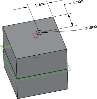
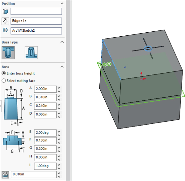
Figure 38.1 shows the Mounting Boss PropertyManager along with the preview of the boss in progress. The part used in this figure is in the download materials available from the Wiley website, with the filename Chapter 38 – right frame.sldprt.

FIGURE 38.1 A mounting boss in progress
The workflow for the Mounting Boss feature is as follows:
- Select a spot on the part that represents where the boss will attach to the part. This can be either a flat or curved face. In the example in Figure 38.1, because I selected a curved face, it's necessary to also supply a direction of pull. If you select a flat face, the Direction selection box in the next step won't be available.
- Select a plane, planar face, edge, or axis to establish the axis of the boss. This is usually the direction of draw. Notice in the part shown in Figure 38.1 that an axis established early in the part is named as the Direction Of Draw. This step is optional. The default is the direction normal to the face selected in step 1.
- Select an existing circular edge to align the boss. The new boss is concentric with the circular edge. This step is also optional. You can choose to use dimensions to locate the boss after the feature is created. If you use dimensions, you cannot locate the boss while the PropertyManager is active.
- The Boss panel of the Mounting Boss PropertyManager is used to establish the height and other dimensions of the central boss. Diameter and draft dimensions are obvious. You can establish height by a dimension or by an “up to” face using the Select Mating Face option. There's no option for an “offset from face” end condition.
- The Fins panel of the Mounting Boss PropertyManager is used to control the alignment, draft, height, width, and patterning of the ribs around the boss. The first box is for a direction vector such as a plane, edge, or axis to establish the rotational orientation of the ribs. You cannot use a sketch for this. The significance of the dimensional values is obvious. The Fin Pattern function is also obvious except for the Equally Spaced option, which is available only when the number selected is 2. Then you must select a vector to establish the orientation of the fins, which form a right angle for a corner.
- The Mounting Hole/Pin panel enables you to specify a pin or hole boss and the associated sizes. It's interesting to me that it doesn't enable through holes or counterbore holes from the outside of the part, along with associated screw sizes for clearance.
- SolidWorks has renamed Favorites in the rest of the software to Styles; however, in the Mounting Boss and the Lip/Groove, it's still called Favorites, and it saves settings like other Favorites/Styles functionality.
- After you have successfully accepted the creation of the boss, if you didn't use a circular edge to locate the boss (step 3), you can expand the Mounting Boss feature in the FeatureManager and edit the 3D sketch under the boss. Inside this sketch is a point, which you can dimension to locate precisely. Remember that dimensions in 3D sketches follow some special rules. To get orthogonal dimensions parallel to X, Y, or Z axes, you'll need to dimension from planes. Three-dimensional sketch dimensions don't snap to horizontal or vertical orientations like 2D sketches.
If you select a flat face for the initial position of the boss, you get a 2D sketch instead of a 3D sketch.
The features created by this tool aren't manually editable. They aren't made of extrudes and Rib features that are accessible behind the Mounting Boss interface. You must go through the Mounting Boss PropertyManager to edit the features, and you cannot edit sketches used to make the features. You can use Move Face to change sizes if you need to make something asymmetrical. As with any SolidWorks feature, you can access dimensions by double-clicking the feature in the FeatureManager or in the graphics window.
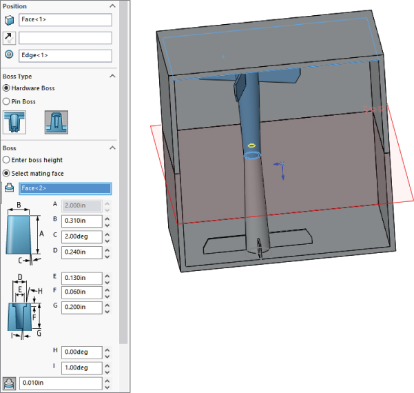
To make a screw boss instead of a pin boss, use the optional setting for Hardware Boss in the Mounting Boss PropertyManager, shown in Figure 38.2.

FIGURE 38.2 Using the Hardware Boss option
An effective way to pattern a single Mounting Boss feature around a part is to use the Sketch Driven Pattern feature. This feature uses a sketch with a set of points where each point represents the center of a patterned instance. Refer to the model in the download materials and examine the Sketch Driven Pattern option at the bottom of the FeatureManager. Use the Chapter 38 – right frame.sldprt file and change to the “nonmirror” configuration if it isn't already there.
Using the Snap Hook and Snap Hook Groove
![]() Snap Hook and Snap Hook Groove are two separate features. Lip/Groove combines both functions into a single PropertyManager to help you get results that work together more easily. Figure 38.3 shows the PropertyManager for the Snap Hook feature, along with a completed hook.
Snap Hook and Snap Hook Groove are two separate features. Lip/Groove combines both functions into a single PropertyManager to help you get results that work together more easily. Figure 38.3 shows the PropertyManager for the Snap Hook feature, along with a completed hook.

FIGURE 38.3 The Snap Hook PropertyManager with a completed Hook feature
The workflow for the Snap Hook feature goes like this:
- Select a spot on the model that corresponds to the center of the undercut edge where the hook intersects the part. It looks like you can select a face or an edge when you first create the feature, but the software always converts the selection to a 3D sketch point when the feature is accepted.
- Select a vector (face, edge, or axis, not a sketch) to set the vertical orientation of the hook, or the “top.”
- Select another vector to define the “front” of the hook (the undercut side).
- Choose to select a mating face or enter a number to define the height of the hook.
This feature uses a 3D sketch point where you made the selection in step 1. You cannot dimension this point while setting up the feature; you can dimension this point only by creating the feature and then going back and editing the 3D sketch absorbed under the feature. This is also the arrangement with the Lip/Groove feature. Remember that you cannot dimension 3D sketches the same way that you dimension 2D sketches. You may need to dimension to planes rather than edges or points to get the dimensions you really want.
The Snap Groove PropertyManager interface is shown in Figure 38.4, along with a cross section of a finished Snap Hook and a Snap Hook Groove. To use the Snap Hook Groove feature, you must have already created a Snap Hook feature. The interface seems to imply that the body that the groove goes into must be in the same part as the body of the Hook feature, but this isn't the case. You can create this feature in-context between a part with a hook and the part to receive the groove, or in a multibody part.

FIGURE 38.4 The Snap Hook Groove PropertyManager with a completed hook and groove
When I model plastic parts, rarely do situations call for a generic Snap feature. Usually, situations require more inventiveness due to space restrictions or curvature or material thickness considerations. The Snap Hook and Snap Hook Groove features are reasonably easy to use, but they may not have the flexibility for application in all situations.
Using Lip/Groove
![]() The Lip/Groove feature enables you to create a matching lip and groove in either a pair of parts in an assembly or a pair of bodies within a single part. Figure 38.5 shows the Lip/Groove PropertyManager creating a groove in a part. The same interface also creates the Lip feature.
The Lip/Groove feature enables you to create a matching lip and groove in either a pair of parts in an assembly or a pair of bodies within a single part. Figure 38.5 shows the Lip/Groove PropertyManager creating a groove in a part. The same interface also creates the Lip feature.

FIGURE 38.5 Using the Lip/Groove feature
The workflow for this feature goes like this:
- Select the part or body to receive the groove.
- Select the part or body to receive the lip. If you only want to create a groove, you can skip the lip steps.
- Select a plane, planar face, straight edge, or axis to establish the direction of pull.
- Select the faces that represent the parting surface along the area to get the lip/groove.
- Select the edges that the lip/groove will affect.
- Set the dimensions for both Lip and Groove features.
In some cases, the automated tools may not be able to create what you need. You can employ one of several manual workarounds to make lips and grooves:
- On a planar parting line, you can use sketches offset from the edges and then extrude either a boss or a cut.
- Using a Thin Feature extrude (boss or cut) can also be effective on planar parting lines.
- Using trimmed and thickened (again, boss or cut) surfaces can be effective but may also be more difficult.
- One of my favorite methods, especially for nonplanar parting lines, is to combine a thin feature with an extrude up to an offset surface body.
- Using a sweep to cut or add material can be effective on either planar or nonplanar parting lines.
Each of these is really a workaround technique and not a specific plastic modeling tool. I won't go into depth on these techniques here. In the download material for this chapter, you'll find example parts that demonstrate each technique.
Using the Rib Feature
![]() The Rib feature is a flexible tool for creating ribs in a number of different situations. Ribs can be drawn in two different orientations, which the SolidWorks interface calls Parallel To Sketch and Normal To Sketch. The names appear on tool tips only when the cursor is hovering over the icons. To be more precise, what they really mean is that the rib will be created either parallel or normal to the sketch plane. If the sketch is a single line, it can be very difficult to tell the difference between parallel and normal.
The Rib feature is a flexible tool for creating ribs in a number of different situations. Ribs can be drawn in two different orientations, which the SolidWorks interface calls Parallel To Sketch and Normal To Sketch. The names appear on tool tips only when the cursor is hovering over the icons. To be more precise, what they really mean is that the rib will be created either parallel or normal to the sketch plane. If the sketch is a single line, it can be very difficult to tell the difference between parallel and normal.
To me, these names aren't very descriptive. I call the two orientations plan view (view from the top, looking in the direction of draw, normal to the sketch plane) and skyline (looking from the side, perpendicular to the direction of draw, rib is parallel to the sketch plane). To me, these names are more intuitively descriptive and better reflect the function of the rib.
Ribs can incorporate draft, extend or trim the feature beyond the sketch automatically, and break normal sketch rules (plan-view ribs only).
Figure 38.6 shows a plan-view rib that violates normal sketch rules. Also shown is the Rib PropertyManager. Several models in the download material show examples of various rib techniques.
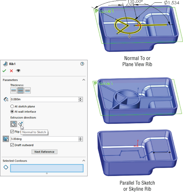
FIGURE 38.6 The Rib PropertyManager and a Rib feature
The Rib feature workflow should be self-explanatory:
- Draw the sketch, either the plan view or skyline. The sketch represents the top of the rib. Material can only be added between the sketch and the rest of the part. Remember that the sketch plane direction makes a difference.
- Initiate the feature and set the type of rib and the direction. Use the Flip Material Side toggle to change the direction of the gray arrow, which should point from the top of the rib toward the part.
- Set the thickness and draft amount and direction.
USING DRAFT IN THE RIB FEATURE
When you create ribs, you almost always apply draft to them. You can apply draft as a separate feature, or you can apply draft as a part of the Rib feature. It's often easier to just do it as part of the Rib feature, but some people like to make all their drafts as separate Draft features to keep the part faces orthogonal for as long as possible, or they just like to organize all the Draft features into a folder at the end of the FeatureManager so that there's never any question about which feature controls the draft.
By default, when you apply draft as a part of the Rib feature, the draft is applied from the sketch end of the rib. This can cause rib thickness problems if you have created a skyline rib where the rib may have various heights. In this case, the top of the rib will vary in thickness, and it may cause the base of the rib to be too thick. When you work this way, sometimes you have to experiment with the proper thickness at the top of the rib in order to get a thickness at the bottom of the rib that doesn't cause sink marks on the outside face of the part. A solution to this is to use the At Wall Interface option, which appears only after you enable Draft in the PropertyManager. Then you can specify the thickness and draft so that the base of the rib maintains a specified thickness.
USING INTERSECTION CURVES AS REFERENCES
![]() Ribs are features that typically go inside hollowed-out parts. For that reason, they're often difficult to visualize, especially when they're on a plane that is deep down inside a part. You may find it useful to use some sort of a reference that shows where the current sketch plane intersects the wall of the part. For this, I typically use intersection curves. This technique can be used in either plan view or skyline-type ribs.
Ribs are features that typically go inside hollowed-out parts. For that reason, they're often difficult to visualize, especially when they're on a plane that is deep down inside a part. You may find it useful to use some sort of a reference that shows where the current sketch plane intersects the wall of the part. For this, I typically use intersection curves. This technique can be used in either plan view or skyline-type ribs.
The Intersection Curve tool is on the Sketch toolbar. While in a 2D sketch, activate the tool and then select faces that intersect the current sketch plane. Deactivate the tool when you're finished. You may want to select all the lines selected by the Intersection Curve tool and turn them into construction geometry. This provides a good reference for the rib sketch without interfering with the Rib feature.
Figure 38.7 shows an example of using an intersection curve as a reference for setting up a rib sketch. The construction lines at the ends and below the right end of the skyline rib sketch are intersection curves.
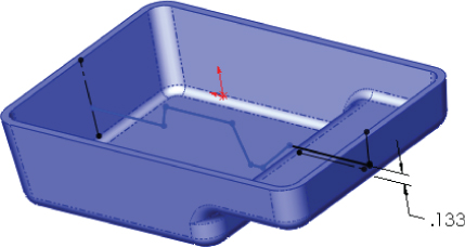
FIGURE 38.7 Using intersection curves as references
At the ends of the shell, the intersection curves serve to give the sketch a reference point to be fully defined. Under the right end of the rib sketch, the intersection curve gives you a reference to dimension the height of the rib in the shallower section of the part. The part shown in Figure 38.7 is in the download material, with the filename Chapter 38 – skyline.sldprt.
TERMINATING RIBS
The Rib feature automatically extends and trims ribs based on your rib sketch. This is a great ease-of-use function, but it tends to lead to sloppy sketching for Rib features. If you sketch a rib and the sketch doesn't lead all the way to the wall of the part, SolidWorks extends it. If your sketch line goes past the wall, SolidWorks trims the rib so that it only goes up to the wall of the part. Figure 38.8 shows how the two straight ribs are extended from the existing sketches on a pair of plan view ribs.
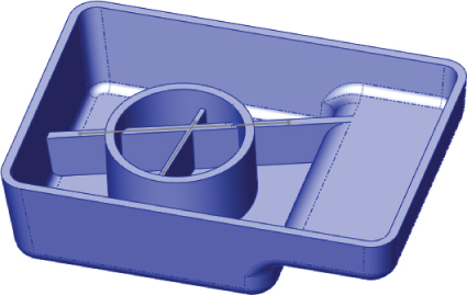
FIGURE 38.8 Extending ribs
Sometimes, you don't want a rib extended to the wall of the part. You may want to terminate a rib at a specific location in the middle of the part. The way to do this is to use a skyline rib and end the skyline sketch with a vertical (plus or minus draft) line that points to the base of the part. Figure 38.9 shows how to accomplish this. Notice that on the left end of the rib, it's extended straight down to the bottom of the part, and on the right side of the rib, it's extended up to the next wall.
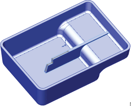
FIGURE 38.9 Terminating a skyline rib
A final termination situation I want to mention is one that can sometimes happen at curved edges. If the extension of the rib cannot be contained by the model, the rib will fail. This situation isn't always as obvious as you might think. When a nonhorizontal rib intersects a curved edge, it usually forces you to fake something a little. Figure 38.10 shows an example of why this happens.
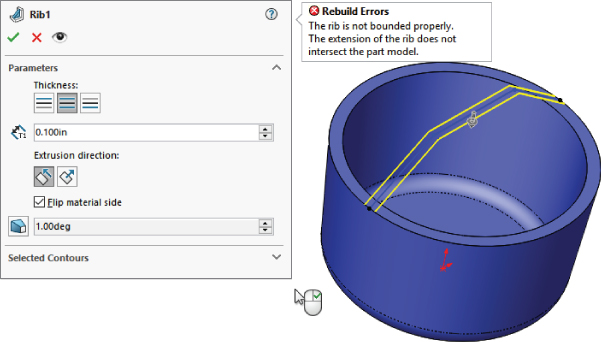
FIGURE 38.10 The part wall doesn't terminate the rib.
The reason for the error shown in Figure 38.10 is that even though the rib sketch intersects the edge of the part, the width of the top of the rib would go past the edge and not intersect anything. One way to deal with this is to make the sketch intersect the part a little closer to the center of the part from the edge.
USING THIN FEATURES
Thin Feature extrusions are sometimes used in place of ribs. Thin features don't have all the specialized options available with the Rib feature, but they do offer simplicity as the main attraction. Thin features can substitute for Rib features when the rib is a stand-alone rib that doesn't touch the side walls of the part. They can be used to sketch and extrude from the bottom of the rib or from the top. When extruding a thin feature with draft, the end (thickness) faces get drafted as well, which might cause a problem if you are trying to attach the rib to a wall. Extruding a thin feature down from the top of the rib can replace a plan-view rib, but it won't enable you to break sketch rules like the plan-view rib.
I personally prefer to use Rib features, except for freestanding ribs where you don't want the sides extended up to the next wall.
Using Draft
![]() SolidWorks Draft is surprisingly powerful for all its simplicity. All the aspects of working with Draft could take up an entire chapter on its own. I'll try to hit the most important points in this brief synopsis. The Draft feature creates three types of draft:
SolidWorks Draft is surprisingly powerful for all its simplicity. All the aspects of working with Draft could take up an entire chapter on its own. I'll try to hit the most important points in this brief synopsis. The Draft feature creates three types of draft:
- Neutral Plane Draft: This feature drafts faces from a plane or planar face where the intersection of the drafted face and the neutral plane is what the draft pivots about.
- Parting Line Draft: This feature drafts faces from a pivot edge on selected edges.
- Step Draft: This feature drafts faces from parting line edges and can create a step at the parting line (similar to pivot draft in other software).
Figure 38.11 shows the PropertyManager of the Draft feature, including the DraftXpert, which is mentioned later in this section.

FIGURE 38.11 Draft and DraftXpert PropertyManagers
NEUTRAL PLANE DRAFT
The workflow for Neutral Plane draft is as follows:
- Select Neutral Plane (the plane or planar face at which the intersection of the drafted face doesn't move). The direction of pull is always normal to the neutral plane.
- Set the draft angle (how many degrees from the direction of pull vector the selected faces should be tilted). This is not a cumulative angle, so applying 3 degrees of draft to a face that is already drafted 5 degrees results in 3 degrees rather than 8 degrees.
- Select the Direction (one side or the other side of the neutral plane). The arrow points in the direction of decreasing material. If you're drafting a surface body, the “decreasing material” concept doesn't apply, so you just have to experiment to see which direction is the one you intend. The Draft feature doesn't have a preview option.
- Select the faces to draft using Face Propagation options. Inner/Outer faces refer to inside or outside loops around the Neutral Plane face. All means that all faces that have an edge on the Neutral Plane face.
PARTING LINE DRAFT
The workflow for Parting Line draft is as follows:
- Select a direction of pull. This can be an edge, axis, sketch line, plane, or planar face. You also have to set the direction to positive or negative along the selected direction.
- Select the parting lines. These are edges of the faces you want to draft. The parting line edges remain stationary while the rest of the face tilts. Along with the parting line selection, you may also need to use the Other Face option. Every edge is adjacent to two different faces. The Draft feature automatically selects the face it thinks you want to draft, but it doesn't always get it right. The Other Face option enables you to intervene when the automatic selection is incorrect.
- Set the draft angle. Remember that you can use the Allow Reduced Angle option if necessary.
STEP DRAFT
The most complex type of draft that SolidWorks creates is the Step draft. Step draft is used on nonplanar parting lines when Parting Line draft would cause the drafted faces to be split into multiple faces.
The word “step” can be said to refer to two different aspects of this feature. First, the parting line can be said to be a “stepped” parting line because it's nonplanar and at two different levels. Second, the draft actually steps out the drafted face at one level of the parting line. Step draft keeps the face intact and introduces an intentional mismatch ledge (step) at the parting line.
Figure 38.12 shows the difference between Parting Line draft and Step draft on a simplified part. The image on the left is the Parting Line draft. The middle image is Step draft, where a ledge is created only on one side of the parting line. The image to the right is essentially double Step draft, where the total step size is minimized by distributing it across both sides of the stepped parting line. The draft in these images is slightly exaggerated to make it easier to see.

FIGURE 38.12 Comparing Parting Line draft to Step draft
The workflow for Step draft is as follows:
- Start with a part that has a stepped split line, where the angled line makes angles of more than 90 degrees rather than less than 90 degrees.
- Create a plane that defines the direction of pull and is located at the level of one of the split lines (for single Step draft) or at the midpoint of the angled line (for double Step draft). The location of the plane will determine the “pivot” point for the drafted faces. Essentially, the line of intersection between this plane and the drafted face will remain stationary and the rest of face will pivot around it.
- Initiate the Draft feature and set the option to Step Draft. Consult your tooling people about whether to use tapered or perpendicular steps. Perpendicular steps are probably the easiest to tool.
- Select the edges of the parting line. Make sure that the yellow arrows indicate the faces to which you want to apply draft.
The Step Draft feature can draft faces only on one side of the parting line at a time. Drafting the faces on the other side of the parting line doesn't require another Step Draft feature. You can use a Neutral Plane feature, using the plane created in step 2 as the neutral plane. It maintains the steps created by the Step Draft feature.
SOME DRAFT LIMITATIONS
One important limitation of draft in SolidWorks is that it cannot draft faces in both directions in the same feature. For example, if you have a parting line on a part, you must first draft the faces on one side of the parting line and then the faces on the other side of the parting line. This results in two separate Draft features rather than one and is simply an inconvenience.
Another inconvenience that affects many features in addition to draft is that you can only draft faces from a single body at a time—an understandable limitation, but annoying and inconvenient.
The biggest limitation is that you can't draft a face if it has a fillet on one of its edges that runs perpendicular to the direction of pull. To get around this, you usually have to tinker with the feature order, or use the DraftXpert to place the draft where it should be. On imported parts, you might have to use FeatureWorks to remove the fillet or Delete Face to reintroduce the sharp corner.
You may sometimes find that draft doesn't work if you don't draft all faces that are tangent to one another. This is the situation where the fillet is on an edge that is roughly parallel to the direction of pull.
WHAT TO DO WHEN DRAFT FAILS
Part of the key to success with the Draft feature is that you have your expectations aligned with the actual capabilities of the software. If you recognize a situation where the draft cannot work, you may be able to correct the situation by changing feature order, combining Draft features into a single feature, breaking the draft into multiple features, or changing the geometry to be more “draft friendly.”
Sometimes, the Allow Reduced Angle option can be used for Parting Line draft. If you use this, follow it up with a draft analysis to make sure that you have sufficient draft in all areas of the model. This option enables the software to cheat somewhat in order to make the Draft feature work. The SolidWorks Help documentation actually has a more detailed explanation of when to use this option. I tend to just select it if a draft fails, particularly if the parting line used becomes parallel or nearly parallel to the direction of pull.
Draft can fail for a number of reasons, including tangent faces, small sliver faces, complex adjacent faces that cannot be extended, or faces with geometry errors. When modeling, it's best to minimize the number of breaks between faces. This is especially true if the faces will be drafted later. Generally, the faces you apply draft to are either flat faces or faces with single-direction curvature. You can't expect SolidWorks to draft anything you throw at it; you should try to give it good, clean geometry.
![]() When Draft does fail for a reason that doesn't seem obvious to you, you should use the Check utility under the Tools menu and also try a forced rebuild (Ctrl+Q) with Verification On Rebuild turned on. The Check utility checks the model for geometry errors. Verification On Rebuild checks more rigorously for features intersecting the model incorrectly. Some features may fail with the option on that would not fail with it off. When this happens, there's something wrong with that feature that the simplified default error checking didn't catch.
When Draft does fail for a reason that doesn't seem obvious to you, you should use the Check utility under the Tools menu and also try a forced rebuild (Ctrl+Q) with Verification On Rebuild turned on. The Check utility checks the model for geometry errors. Verification On Rebuild checks more rigorously for features intersecting the model incorrectly. Some features may fail with the option on that would not fail with it off. When this happens, there's something wrong with that feature that the simplified default error checking didn't catch.
DRAFTXPERT
DraftXpert is a tool used to create multiple Neutral Plane Draft features quickly. You can also use it to edit multiple drafted faces without regard for which features go to which faces.
Using Indent
![]() Indent is a feature that uses a solid body as a tool and indents a thin-walled area in the target part around the tool. For example, if you're building a plastic housing around a small electric motor, then the Indent feature shapes the housing and creates a gap between the housing and the motor. Figure 38.13 shows the PropertyManager interface for the Indent feature, as well as the geometry created by Indent.
Indent is a feature that uses a solid body as a tool and indents a thin-walled area in the target part around the tool. For example, if you're building a plastic housing around a small electric motor, then the Indent feature shapes the housing and creates a gap between the housing and the motor. Figure 38.13 shows the PropertyManager interface for the Indent feature, as well as the geometry created by Indent.
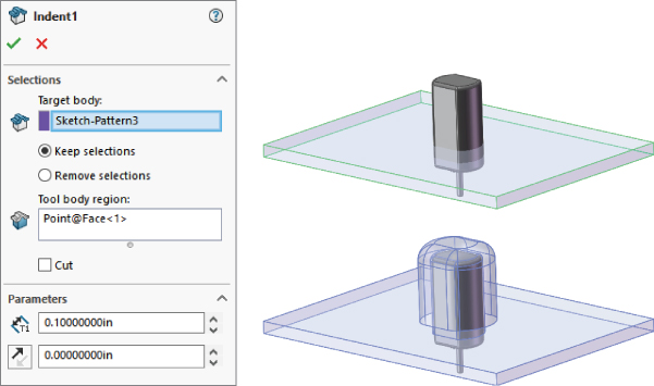
FIGURE 38.13 Using the Indent feature
In this case, the small motor is placed where it needs to be, but there's a wall in the way. Indent is used to create an indentation in the wall by using the same wall thickness and placing a gap of .010 inch around the motor. The motor is brought into the wall part using the Insert ➢ Part command. This is a multibody technique. (Multibodies are examined in detail in Chapter 31, “Modeling Multibodies.”)
The workflow for Indent is as follows:
- Open or create a thin-walled part (plastic, sheet metal, machined, and so on) in which you want to create an indentation.
- Create a new body that will be the positive shape of the negative indentation. You can use Insert ➢ Part to insert an external preexisting part if you want.
- Start the Indent command by choosing Insert ➢ Features ➢ Indent.
- Select the thin-walled part into which you want to put the indentation (as Target Body).
- Click an area on the tool body and change the Keep or Remove option as necessary. Use Keep when you select a location on the tool body where you want to create a thin-walled area; use Remove if you want the selected area to be free of material.
- Set the Thickness for the material thickness and the Clearance for free space between the tool body and the new thin-walled material.
The Indent feature is particularly effective if you have a part that is nearly finished with lots of detail on it that might be lost by rolling back and making drastic changes to the feature history. (It also works in assemblies, where a part can be the Tool in an Indent feature to modify the Edited part.)
The Cut option is good for non-thin features, where you want an offset cut-with-body. It's just like the Combine (subtract) tool, but with the ability to add an offset.
Anecdotally, the Indent feature is one of those tools that I can say has really saved me a lot of time. I had a customer ask for a major redesign on a plastic assembly that would have meant redoing all the work I had done up to that point. Instead, I was able to create a tool body, use it to indent the master model with a constant wall thickness, and proceed like nothing had happened. So, it saved me tens of hours on this particular project. Keep an open mind about unfamiliar tools. You may get an idea some day and save yourself a lot of time.
Working with Shell
![]() The Shell feature is a powerful yet sometimes tricky feature to work with in SolidWorks. Many users just expect it to work regardless of the condition of the geometry, but it requires that some simple conditions be met. In general, to allow the Shell feature to work, you must have a model where the minimum outside curvature (convex) is greater than the shell thickness. Shell works in 3D much like the offset sketch works in 2D. If the curvature is too small, you cannot offset an arc to the inside. The same applies to Shell; the thinner the shell, the more likely it is to work.
The Shell feature is a powerful yet sometimes tricky feature to work with in SolidWorks. Many users just expect it to work regardless of the condition of the geometry, but it requires that some simple conditions be met. In general, to allow the Shell feature to work, you must have a model where the minimum outside curvature (convex) is greater than the shell thickness. Shell works in 3D much like the offset sketch works in 2D. If the curvature is too small, you cannot offset an arc to the inside. The same applies to Shell; the thinner the shell, the more likely it is to work.
Also, generally speaking, if the body you are shelling doesn't have faces that are tangent to one another, you'll have fewer problems, although faces that are nearly tangent or very pointy can sometimes cause problems.
You can use Shell to hollow out a solid, such as a bottle, as shown in Figure 38.14. You can also use the Shell feature to “shell to outside,” which adds material to the outside and removes the original solid.

FIGURE 38.14 The Shell feature can create multi-thickness shells.
USING MULTI-THICKNESS SHELL
Figure 38.14 shows the PropertyManager set up for a multi-thickness shell. In this case, the bottom of the bottle is 0.150-inches thick, while the rest of the bottle is 0.050-inches thick. The top of the bottle is selected so that it's open. If you don't select a face to be open, the bottle will simply be hollow with no openings. The image on the right in Figure 38.14 shows half of the bottle in Wireframe display to help you visualize the thickness differences. To get a better view of this model, you can find it in the download materials, with the filename Chapter 38 – creased bottle.SLDPRT.
An important part of using the Multi-Thickness settings is to remember that SolidWorks can't assign different thicknesses to faces that are connected by tangency. All the adjacent tangent faces must have the same thickness. Another way to say this is that adjacent faces that are to have different thicknesses must not be tangent to one another. The reason for this is that SolidWorks cannot transition between two thicknesses when the two faces are tangent.
USING SHELL OUTWARD
Shell Outward is another option, and it is especially useful for bottles. You may be more interested in modeling the contents of a container than the actual container. To help you visualize this idea, think of modeling a liter of frozen water—not the bottle, just water frozen in the shape of the inside of the bottle. Now that you have the contents, you want to create the bottle. This is what the Shell Outward option is meant to do. Figure 38.15 shows the result, where the inside is the original modeled shape and the bottle shown on the outside was “grown” by the Shell Outward option.
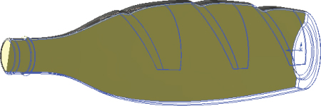
FIGURE 38.15 Creating a bottle from a shaped volume
Figure 38.16 shows one of the trickier usages of the Shell feature. This figure shows a planter tray that's manufactured by thermoforming. It may be difficult to tell how to model a part like this, because it could be shelled from either side—the top or the bottom.
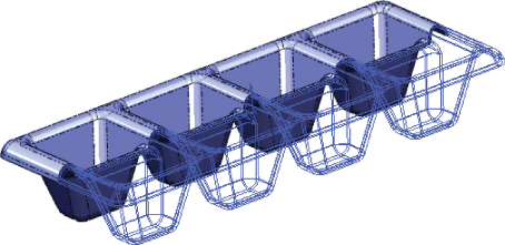
FIGURE 38.16 Getting tricky with the Shell feature
In this part, several faces were removed in the Shell feature, which you may not think of doing with the conventional examples used to show this function, but it works very well for cases like this, especially thermoformed type parts.
Open the file called Chapter 38 – potting tray.SLDPRT from the download materials. The final feature is used to allow you to better visualize the effects of the shell.
UNDERSTANDING THE SHELL WORKFLOW
The workflow for using the Shell feature to produce the potting tray part goes like this:
- Create a solid part where one side of the solid represents the faces of the finished model. The other side may be a simple block. Figure 38.17 shows the model before applying the Shell feature.

FIGURE 38.17 Preparing to shell the potting tray part
- Initiate the Shell command. In the Faces To Remove selection box, select all the faces that should be removed or that will become thickness faces. This should amount to the six faces of the block sitting on top of the tray.
- Use the Show Preview option if you are having difficulty visualizing the result. Be aware that this option may slow down the operation of the software while the Shell PropertyManager is open, but it will help you see the result based on your current selection.
Using the Vent Feature
![]() The Vent feature is highly specialized and is intended for both sheet metal and plastic parts. Figure 38.18 shows examples of vents.
The Vent feature is highly specialized and is intended for both sheet metal and plastic parts. Figure 38.18 shows examples of vents.

FIGURE 38.18 Examples of the Vent feature
The part used in Figure 38.18 can be found in the download materials in the file called Chapter 38 – Vents.SLDPRT.
A Vent feature has four main components:
- Boundary
- Ribs
- Spars
- Fill-In Boundary
Figure 38.19 shows the PropertyManager of the Vent feature. This is represented as a single column in the PropertyManager, but here it's split into two columns to fit the format of this book.

FIGURE 38.19 The Vent PropertyManager is used to specify the geometry of the feature.
The Vent feature also has several rules, most of which aren't explained by the Help feature or the interface:
- All of the sketch elements must be in the same sketch.
- The entire feature must exist on a single face.
- No sketch elements can hang off of the face.
- The Fill-In Boundary may not have a nested contour.
- You must have one rib before you can create any spars.
- Spars and Ribs can be interchangeable as long as at least one sketch element in the Rib selection crosses the boundary.
- If Ribs or Spars have sketch elements that aren't tangent (lines meet at an angle), the intersections will have notches on the ends, as if each sketch line were extruded individually (see the circular and triangular examples in Figure 38.18). As a workaround, you can remove the notches by using the Delete Face feature with the Delete and Patch option, selecting the two flat faces of the notch to be deleted.
The Boundary is the outline of the cutout. In Figure 38.20, the Boundary is the elements of the rectangle. The Ribs are the concentric circles, and the Spars are the radial lines.
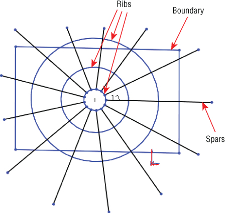
FIGURE 38.20 Identifying the components of a Vent feature
The workflow for a Vent feature is as follows:
- Create a sketch that contains the Boundary, Ribs, Spars, and Fill-In Boundary. Rib and Spar sketch elements represent the mid-line of the feature.
- Select each element of each Boundary, Rib, Spar, and Fill-In Boundary in its respective selection box.
- Set the widths and thicknesses of each item.
- (Optional) Change the Radius For The Fillets option in the Geometry Properties panel to add fillets to all sharp corners of the feature. If a fillet fails, it won't identify which corner failed; the whole feature will fail.
- Use the Flow Area panel to calculate the open space of the vent.
- Use the Favorite panel of the Vent PropertyManager to store commonly used settings. Favorites can be saved externally and shared with other users.
Using Plastic Evaluation Tools
The plastic evaluation tools in SolidWorks enable you to automatically check the model for manufacturability issues such as draft, undercuts, thickness, and curvature. The tools used to do this are the Draft Analysis, Thickness Analysis, Undercut Checker, and Curvature tools.
Using Draft Analysis
![]() The SolidWorks Draft Analysis tool is a must when you're working with plastic parts. The part shown in Figure 38.21 has many of the situations that you are going to encounter in analyzing plastic parts. The Draft Analysis tool has four major modes of display:
The SolidWorks Draft Analysis tool is a must when you're working with plastic parts. The part shown in Figure 38.21 has many of the situations that you are going to encounter in analyzing plastic parts. The Draft Analysis tool has four major modes of display:
- Basic
- Gradual Transition
- Face Classification
- Find Steep Faces

FIGURE 38.21 Basic draft analysis results
Draft Analysis is found in the View ➢ Display menu and, like the Section View tool, is either on or off. This is beneficial because it updates face colors dynamically as you model. It also has some drawbacks. The display method for the tool leaves the colors looking very flat, without highlights on curved faces, which makes parts—especially curved parts—very difficult to visualize.
BASIC
The Basic draft analysis (with no options selected) simply colors faces red, green, or yellow. Colors may display transitioning if the draft shifts between two classifications. This transition type is shown in Figure 38.21 in the image to the right. For a clearer view of this method, look at the Chapter 38 Draft Analysis.sldprt part in the download materials.
You can perform all types of draft analysis in SolidWorks by selecting a reference flat face or plane and setting a minimum allowable angle. In Figure 38.21, all walls have at least a 1-degree draft, except for the rounded edge shown in the image to the right and the dome. Both of these shapes transition from an angle less than 1 degree to an angle greater than 1 degree.
This basic analysis is good for visualizing changes in draft angle, but it also has some less desirable properties, which become apparent as you study the other types of draft.
GRADUAL TRANSITION
Although the Basic draft analysis can show a transitioning draft, the Gradual Transition draft analysis takes it a step further. With the Gradual Transition draft, you can specify the colors. It's also useful because it can distinguish drafts of different amounts by color. It may be difficult to tell in the grayscale image in Figure 38.22, but the ribs, which were created at 1 degree, have a slightly different color than the floor of the part, and the walls also have a different color. Notice that cavity and core directions have different colors as well (called Positive and Negative draft in the draft analysis). You may want to open this part in SolidWorks, re-create the settings, and run the analysis so you can see the actual colors.
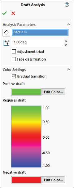
FIGURE 38.22 The Gradual Transition draft analysis
Some problems arise when you use this Display mode, the first being the flat, non-OpenGL face shading that's used to achieve the transitioning colors. This often makes it difficult to distinguish curved faces and faces that face different directions. The second problem is that you cannot tell that the boss on top of the dome has absolutely no draft. In fact, there's no way to distinguish between faces that lean slightly toward the cavity and faces that lean slightly toward the core. The third problem is the strange effect that appears on the filleted corners. The corners were filleted after you applied the draft and before the shell, so the filleted corners should have exactly the same draft as the sides; however, from the color plot, it looks to be a few degrees more.
FACE CLASSIFICATION
Face Classification draft analysis groups the faces into classifications using solid, nontransitioning colors. You'll notice a big difference between the coloration of the Face Classification draft analysis faces and of the Basic or Gradual Transition faces. Face Classification uses OpenGL face shading, which is the same as that used by SolidWorks by default. This allows for better shading and differentiation between faces that face different directions. The Basic Analysis coloration looks like all the faces are painted the same flat hue, regardless of which direction they are facing, which makes shapes more difficult to identify. The non-OpenGL alternative shading method makes it possible to display a transition in color. SolidWorks OpenGL shading cannot do this.
Another advantage of using the OpenGL shading is that the face colors can remain on the part after you have closed the Draft Analysis PropertyManager.
Face Classification draft analysis also adds a classification that isn't used by the Basic draft analysis. The term straddle faces refers to faces that straddle the parting line, or faces that, due to their curvature, pull from both directions of the mold. These are faces that need to be split. On this part, a straddle face is shown in Figure 38.23.

FIGURE 38.23 Face Classification draft analysis and a straddle face
The light bulb icons to the left of the color swatches enable you to hide faces by classification. This is useful when you're trying to isolate certain faces or visualize a group of faces in a certain way. This can be an extremely useful feature, especially when you have a very complex part with a large number of faces, some of which may be small and easily lost in the mix with other larger faces.
The face counts that appear in the color swatches are very helpful features that are absent from the Basic draft analysis. Consider using DraftXpress for situations where you have to add draft to models, as it has built-in draft analysis.
FIND STEEP FACES
A steep face is defined as a face that transitions from less than the minimum angle to more than the minimum angle. Steep faces are different from straddle faces in that straddle faces are actually positive and negative, while steep faces are either entirely positive or entirely negative. On this part, the dome inside the part is classified as a steep face, as shown in Figure 38.24.
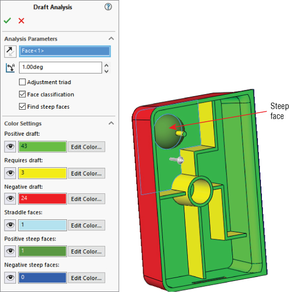
FIGURE 38.24 A steep face
UNDERSTANDING THE DRAFT ANALYSIS WORKFLOW
The workflow for the Draft Analysis tool is as follows:
- Open a part for which you want to analyze the draft.
- Select View ➢ Display ➢ Draft Analysis, or select it from the Evaluate tab of the CommandManager.
- Select a plane or planar face for the direction of pull, and then set the options you want to use to visualize the draft on your part. The draft colors display immediately after you select the direction of pull.
- If you want to keep the colors on while you work, click the green checkmark icon. The Draft Analysis icon on the toolbar and menu will display as selected. If you don't want to see the colors anymore, click the red X icon. If you click the green checkmark icon and then later want to turn off the Draft Analysis display colors, you must deselect the Draft Analysis icon in the toolbar or menu.
Using Thickness Analysis
![]() You can run Thickness Analysis in two modes: Show Thin Regions and Show Thick Regions. Of these, Show Thick Regions is the most versatile.
You can run Thickness Analysis in two modes: Show Thin Regions and Show Thick Regions. Of these, Show Thick Regions is the most versatile.
USING THE SHOW THIN REGIONS OPTION
The Show Thin Regions option, or the Thinness Analysis, requires you to input a minimum acceptable thickness. Every face with a thickness above this value is turned a neutral gray, and every face with a thickness below this value is displayed on a graduated scale.
Figure 38.25 shows the PropertyManager for this analysis and its result on the same part used for the draft work in the preceding sections.

FIGURE 38.25 Results of the Thinness Analysis option
One of the things to watch out for here is that some anomalies occur when you apply this analysis to filleted faces. The faces shown as colored were created by the Shell feature and should be exactly 0.100 inches thick. However, it does correctly represent the undercut on the end of the part and the thickness of the ribs. A nice addition to this tool would be the identification of minimum thickness faces. Perhaps you can submit an enhancement request.
USING THE SHOW THICK REGIONS OPTION
The Show Thick Regions option works a little differently from Show Thin Regions. You need to specify an upper-thickness limit value, beyond which everything is identified as too thick. In these examples, the nominal wall thickness of the part is shown as .100 inches, and the thick region limit is set to .120 inches. For this type of analysis, the color gradient represents the thicknesses between .100 inches and .120 inches, while in the Thinness Analysis, the color gradient represents the values between .100 inches and 0 inches.
The analysis can produce some anomalous results, especially at the corners and also in the middle. Again, this is a useful tool, if not completely accurate. You can use it to find problem areas that you may not have considered, but you should certainly examine the results critically.
This feature can generate a report, which to some extent answers questions about how or why it classifies faces in the way it does. To get a complete picture of the situation, it may be useful to look at the report when you are using the results to make design or manufacturing decisions. A sample of the report is shown in Figure 38.26.

FIGURE 38.26 A sample of a Thickness Analysis report
UNDERSTANDING THE THICKNESS ANALYSIS WORKFLOW
The workflow for the Thickness Analysis tool is as follows:
- Open a thin-walled part with some variations in thickness.
- Start the Thickness Analysis tool by selecting Tools ➢ Thickness Analysis or by clicking the icon on the Evaluate tab of the CommandManager.
- Select the Thin or Thick Regions option, depending on what you are most concerned about.
- For a Thin Region analysis, enter the lowest acceptable thickness. For a Thick Region analysis, enter the low and the high acceptable thickness values.
- (Optional) Select individual faces for local analysis in the Performance/Accuracy panel. This will also give you the option to get a more accurate display. The default is the least accurate option. Accuracy comes at the cost of longer analysis time.
- Click Calculate. This calculation may take a few seconds or longer, depending on the complexity of your part. It isn't an instantaneous display.
- Observe the color gradient on the faces. Blue indicates that the wall is too thin, and red indicates that it's too thick.
Undercut Analysis
![]() The Undercut Analysis tool is in the View ➢ Display menu and on the Evaluate tab of the CommandManager. It is also an on or off display tool, which changes dynamically as you change the model. Undercut Analysis is conceptually flawed in that it gives incorrect results every time. However, if you think of the labels as being changed slightly, the results become partially usable.
The Undercut Analysis tool is in the View ➢ Display menu and on the Evaluate tab of the CommandManager. It is also an on or off display tool, which changes dynamically as you change the model. Undercut Analysis is conceptually flawed in that it gives incorrect results every time. However, if you think of the labels as being changed slightly, the results become partially usable.
Even if you and your mold builder know that a part has absolutely no undercuts, the Undercut Analysis tool nonetheless always identifies all the faces to be undercut. In fact, the only faces that this tool identifies as not undercut are faces that have no draft on them (even if they are in fact undercut). The only time it correctly identifies an undercut is when it classifies the undercut as Occluded Undercut. Faces that have no draft and are occluded undercut are improperly identified as simply No Undercut.
You may want to avoid this tool because too much interpretation of incorrect results is necessary; however, if you still want to use it, here is a translation guide that may help:
- Direction 1 Undercut: Should read Pull from Direction 2
- Direction 2 Undercut: Should read Pull from Direction 1
- Straddle Undercut: Should read Straddle Faces
- No Undercut: Should read No Draft in the Primary Draft Direction, but may be Occluded Undercut Faces
- Occluded Undercut: Should read Occluded Undercut Faces that have draft in the completely irrelevant primary draft directions; doesn't include occluded undercut faces that have no draft in the primary direction
Figure 38.27 shows the PropertyManager for this function and the results. If you want to test it for yourself, the part is in the download material with the filename Chapter 38 Draft Analysis.sldprt.
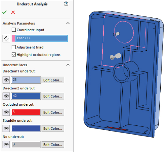
FIGURE 38.27 The results of the Undercut Detection tool
Understanding the Undercut Analysis Workflow
The workflow for the Undercut Analysis tool is as follows:
- Open a plastic part model in which you want to find undercuts.
- Open the Undercut Analysis tool from View ➢ Display or using the icon on the Evaluate tab of the CommandManager.
- Select an axis, flat face, or plane to establish the direction of pull of the mold.
- Interpret the results using the suggested labels listed earlier.
- If you want to keep the colored display, click the green checkmark icon. If you want the model to display with the normal model colors, click the red X icon. If you chose the green checkmark icon but want to turn off the color display, turn off the Undercut Detection tool by clicking on it again on the toolbar or in the menu.
The Bottom Line
SolidWorks provides a vast amount of plastics functionality. The more you use these features, the more power you'll find in them. They'll become second nature after you've used them for a while. The power and flexibility are amazing when you think of the incredible range of parts that you can make and evaluate with these features. Automated functions aren't the answer to all problems, however. You need to be well versed in workaround techniques for more complex situations.
- Master It Follow these steps to create matching mounting bosses:
- Create a new part, and extrude a solid box using the Midplane option, with the size of the box at least 4 × 4 × 4.
- Use the Shell feature to hollow the box out with a wall thickness of 0.1″, without selecting a face to remove.
- Use the Intersect feature and select the solid body and the original sketch plane to create two separate bodies. Make sure to turn off the Merge Result option. You want to keep the outer two shelled bodies so you are left with two halves of an open box.
- Sketch a circle on a face of the block parallel to the split plane, as shown here.
- Initiate a mounting boss, using the circle to locate the boss, and an edge perpendicular to the split as the direction.
- Select Hardware Boss type and the Head option. Other options are shown in the following graphic. You cannot go back to change the boss from Hardware Boss to Pin Boss later.
- Use the settings in the preceding graphic for the fins. Make sure you use a model edge to fix the direction of the fins.
- Accept the Mounting Boss options.
- Apply a section view so you can see the inside of the boxes and still see the mounting boss.
- Start the Mounting Boss feature again. Select the face opposite the original mounting boss face to put the new boss on. Select a circular edge of the first boss to locate the new boss. Select the Hardware Boss, Thread type as shown in the following graphic. Use a flat mating face to specify the length.
- Determine the direction of the fins of the second boss and accept the second Boss feature.
- Save the part.

- Master It Open the part you created in the previous Master It exercise and prepare to add a Lip/Groove feature to it.
- Use the Save As functionality to rename the part to
Master It Lip-Groove.sldprt. - Use the tool tips in the Lip/Groove Property Manager shown here for each selection box to make proper selections for the lip (add material) and groove (remove material).
- The visualization may be difficult for this feature, but with a multibody part, SolidWorks temporarily hides the appropriate body at the appropriate time to allow you to make the selections.
Master It The Undercut Analysis tool has been incorrect since it was added to the software. It's a little embarrassing considering the fact that the rest of the software is generally pretty good. It's like it was developed by someone who didn't understand the concept at all. Your mission, should you choose to accept it, is to write an enhancement request to SolidWorks to get them to fix this tool using either my suggestions earlier in the chapter or your own suggestions.
- Use the Save As functionality to rename the part to