
Appendix A
The Bottom Line
Chapter 1: Introducing SolidWorks
Easy access to your tools cuts just seconds out of your work time every day, but a good habit will cut minutes, and several good habits can cut hours.
- Master It After SolidWorks has been installed as shown in this chapter, find the desktop icon, and put it on your taskbar or other easy-to-access interface element.
- Solution If SolidWorks is going to be part of your everyday tools, make sure it is easy to access.
File organization is one of the keys to a successful SolidWorks implementation. While I don't expect you to have everything figured out at this stage in your learning, you need to start thinking about how to manage your SolidWorks libraries of templates and key features as well as your project data.
- Master It Make sure you know where the settings in Tools ➢ Options are located for identifying the locations for templates, and change this location if necessary.
- Solution You may need to specify a network drive if you are sharing templates with other users. You may also need to customize some templates for your company's particular needs. Make sure you are also familiar with the specific file extensions that SolidWorks uses.
One of the key concepts of managing SolidWorks is associativity. Data created in one file can be shown in another file. For example, part data is shown in both assemblies and drawings.
- Master It Open a SolidWorks drawing (
*.slddrw) and drag a SolidWorks part (*.sldprt) onto it. Make a change to the part and watch it update on the drawing. - Solution The easiest way to make a simple change is to double-click on the part shown in the drawing, and then double-click on a dimension. Change it by a small amount to try to avoid rebuild errors.
Chapter 2: Navigating the SolidWorks Interface
- Learn the different parts. The SolidWorks interface has many elements because SolidWorks has so much functionality. You can access most elements multiple ways, which can be liberating because it offers options, but it also can add to the confusion because there is so much to know. You do not need to know every way to do everything; you only need to know the best way for you.
- Master It Identify each area around the SolidWorks window.
- Solution Use Figure 2.1 and tool tips to go around the interface and name each area.
- Customization is key. Customization opportunities in SolidWorks are vast. Everyone has different tastes and preferences when it comes to running the interface. Some prefer the keyboard, some the mouse. Some prefer the touch interface. There are different strategies that depend on your specific situation—for example, saving space, saving mouse travel, or saving mouse/keyboard clicks. SolidWorks has touch interface options, as well as various accessibility tools intended to accommodate special needs such as different input devices or color blindness.
- Master It Create some simple keyboard shortcuts (hotkeys) for the functions you think you will use the most.
- Solution Start from the sample Excel list of existing hotkeys, and add some of your own for things like Tools ➢ Options or Tools ➢ Evaluate ➢ Measure.
- Manipulate multiple windows. Manipulating multiple windows is important in all computer use, but especially in CAD, where you work with enormous amounts of data and numbers of documents that surpass other types of programs.
- Master It Open several sample documents from the Wiley download data and practice manipulating the windows.
- Solution Use the window controls in the upper-right corner of the SolidWorks application to span multiple displays. Use Ctrl+Tab to cycle through open SolidWorks documents and Alt+Tab to cycle through open Windows applications. Use the R key to see the Recent File list.
After using this chapter to find the various ways of using the interface, you can develop the way that is most comfortable for you and stick with it. Save the settings and share them with other users or move them to other computers where you work.
Chapter 3: Working with Sketches and Reference Geometry
- Create new sketches and edit existing ones. In SolidWorks, each sketch is named and must be on a plane or planar face. You can edit only one sketch at a time, and there are things you cannot do while in a sketch.
- Master It Practice creating new sketches and using the various sketch entities on the Sketch toolbar to familiarize yourself with the range of tools that are available and how they work.
- Solution Practice working with dimensions and sketch relations. Use the Smart Dimensions tool to create dimensions on line and arc geometry. Use relations to control how dimensions move and change sketches when the dimensions increase or decrease in value.
- Create new reference geometry and use the planes to create new sketches. As you get deeper into this book, you will learn more uses for the Reference Geometry tools. For now, the primary function is to establish planes for sketches without relying on adding relationships to solid geometry.
- Master It Practice moving or redefining planes to see how the change affects the resulting 3D geometry. Also build your skills by creating planes using the available options. If you can imagine a way to define a plane, use the three selection boxes and available constraints to see how many different types you can create.
- Solution Use the Plane Wizard to create new planes. Ctrl+drag a plane to make an offset plane. Rename planes to denote their purpose. Start sketches on a couple of planes.
- Use a range of sketch entities. While you can often get by using just lines and arcs, there are times when more advanced sketch entities are more appropriate. Ellipses, parabolas, conics, splines, even slots, polygons, and sketch text are all valid sketch entities that are very useful in certain situations.
- Master It Practice using some of the more advanced sketch entities on the Sketch toolbar.
- Solution Remember that you can use either the Click+click or click-and-drag method to create sketch entities. Follow the prompts in the lower-left area of the SolidWorks window.
Chapter 4: Creating Simple Parts and Drawings
SolidWorks data is made of parts, assemblies, and drawings. In this chapter, you learned how to create simple examples of each type.
- Master It Create a simple block with holes in it, where every item is dimensioned fully. Use an existing SolidWorks template.
- Solution Fully dimensioned means that all the sketch elements are black and cannot be dragged. Use the sample part from the download material for this chapter called
Sample Solution Simple Block.sldprt. - Master It Create a simple assembly where you bring together some of the parts that you created or worked with in this chapter, and use mates to locate them with respect to one another.
- Solution Remember that the first part you bring into an assembly will be locked in place. Other parts will be able to move around until you mate them into place. Work with mates to mate flat faces and/or holes. Refer to the
Sample Assembly Solution.sldasmin the downloadable material. - Master It Create a simple drawing of a single part you made earlier in this chapter. Fill in some custom properties, and make sure the properties propagate over to fill out the title block on the drawing. Use various types of views, annotations, symbols, and dimensions.
- Solution Drag the part onto the drawing sheet. Use Insert ➢ Model Items to place dimensions from the model into the drawing. Use the file
Sample Solution Simple Block.slddrwas a reference.
Chapter 5: Using Visualization Techniques
- Visualization is one of the most important tools in SolidWorks. Visualization is a key function of the SolidWorks software. You will use these tools multiple times an hour and, in some cases, constantly throughout the day. Visualization can be an end to itself if you are showing a design to a vendor or client, or it can be a means to an end if you are using visualization techniques to analyze or evaluate the model. In both cases, SolidWorks presents you with an astounding list of tools to accomplish the task. The tools range from the analytical to the cosmetic, and some of the tools have multiple uses.
- Master It Practice using the keyboard and mouse display controls, including the arrows and modifier keys. Access the Orientation box with Ctrl+spacebar and manipulate the view using each of these tools.
To become acquainted with the names of all the tools on toolbar, use the mouse to hover over the Heads-Up View toolbar. Make sure to look at all the drop-downs and flyouts.
- Solution The middle mouse button is frequently used in SolidWorks.
- Master It Use the DisplayManager and the Task pane to access all of the information and tools to apply appearances and visual properties to your model. Make sure to use the DisplayPane flyout from the FeatureManger to have quick access to appearances applied to your part.
- Solution SolidWorks did not make this part of the interface simple or compact, so it may take some extra time to understand and remember where all of the various controls and information are located.
- Master It Acquaint yourself with all of the settings available in Tools ➢ Options ➢ Colors and ➢ Display. Don't forget the settings under Tools ➢ Options ➢ Document Properties ➢ Model Display. Create templates with the background and visual properties you want to use.
- Solution You may have to refer back to this chapter to make sure you understand some of the settings and options available for backgrounds, colors, and templates. Compare templates with your coworkers.
- Master It Practice using the keyboard and mouse display controls, including the arrows and modifier keys. Access the Orientation box with Ctrl+spacebar and manipulate the view using each of these tools.
Chapter 6: Getting More from Your Sketches
- Edit sketch relations. Effectively using sketch relations is a fundamental skill that you need to have to be successful with SolidWorks. You will use them constantly to make sure your models behave predictably to change.
- Master It Open one of the sample parts from this chapter, show the flat tree, and edit each sketch. Make sure you understand what each sketch relation is doing.
- Solution You will create each feature once, but you will edit features many times. Editing skills are actually more important than creation skills, because you will spend more time editing.
- Reverse engineer a simple part using digital images. Take pictures from at least two sides of a simple object you can model using simple extrude features, trying to make the photos look like drawing views. Use the images as sketch pictures, align the edges on the photo with the X and Y of the sketch, and sketch over them.
- Master It Insert the photos into sketches and model with the image as a reference.
- Solution It is often useful to have a ruler in the image, or to have an accurate measurement of an edge that you can identify in the image.
- Create a wireframe representation of a chair from 3D sketches. 3D sketches are frequently used in many types of design. Getting some practice drawing lines in 3D space will help you gain command of these tools.
- Master It Start by creating the centerlines of the square members of a simple wooden chair.
- Solution It will be easier if you start from the origin or create construction geometry connected to the origin. Make sure you have a plan for which part of the chair is in positive X territory, and so on. Use multiple viewports and a rotated view. Use dimensions and sketch relations to make everything update together when the sketch is changed.
Chapter 7: Modeling with Primary Features
SolidWorks has a wide selection of feature types to choose from, ranging from simple extrudes and revolves to more complex lofts and sweeps. Some features have so many options that it may be difficult to take them all in at once. You should browse through the models from the downloads for this chapter and use the Rollback bar (described in detail in Chapter 2, “Navigating the SolidWorks Interface”) to examine how the parts were built. Then you can try to create a few on your own. The best way to learn these features is to use them on practice parts and through experimentation. Curiosity is your greatest teacher.
- Master It Copy the part (remodel it from scratch) called
LowerLinkBibleBike ch7.sldprtfrom the download material. Use the Measure tool under Tools ➢ Evaluate ➢ Measure. - Solution If you're having trouble getting the information you need from the Measure tool, use the Rollback bar ➢ Tiled windows ➢ Edit Feature and double-click to find dimensions.
Depending on the type of work you do, Fillet features can be an important part of your job. Work through this exercise to get some practice with fillets.
- Master It Open the part
Chapter 7 fillet example.sldprtfrom the download materials for this chapter. Add fillets to all edges except the outer edges on the Top plane. Remove existing fillets where necessary. - Solution As a hint, try to work through the fillets in order from the largest to the smallest. Remember this part will have draft on it. There is already some draft. Remember also that there are a couple of aids for applying a lot of fillets at once—selecting faces or features and using the FilletXpert selection toolbar.
Whether you create a lot of complex shapes or do machine design at your job, sweeps can be important features to master. Open the part Chapter 7 Curves.sldprt and examine how each feature was made. use the Rollback bar, expand all features, and use the Flatten Tree option (RMB on name of part in FeatureManager, or use Ctrl+T) to try to understand as much as you can about how it was made.
- Master It The curves are the tricky part to this one. You have a 3D sketch, a helix, a projected curve (one sketch projected onto another), and a composite curve (two curves added together end to end). Re-create
Chapter 7 Curves.sldprtusing your own dimensions. - Solution Remember, SolidWorks does not always display the features in the same order in which they were created, so you may have to use the Flatten Tree (Ctrl+T) command to understand how each curve came to be through multiple other items.
Chapter 8: Selecting Secondary Features
SolidWorks has a wide range of features beyond the basic extrudes and revolves. You saw the depth of the standard features in Chapter 7; now in Chapter 8, you have seen the breadth of some of the less-used, but still useful operations. You won't use each of these secondary features every day, but it is nice to know that if you need to show a model in a flexed in-use state, you at least don't have to directly model the deformed part manually.
Springs are very commonly needed to be custom designed in small mechanisms that you might be called upon to create. The ability to model these items is a valuable skill.
- Master It Use a Helix and a 3D sketch to create a sweep path for a spring with elongated ends for use in a light mechanism.
- Solution Remember that you can convert the helix into a 3D sketch entity to make it easier to connect to in the 3D sketch.
Packaging and fixturing are additional types of design and modeling that are important for an engineer to master. Create a cavity such that the file named Chapter 8 Bottle.sldprt can nest into it.
- Master It Use the Indent feature to create the cavity in a thin sheet of material.
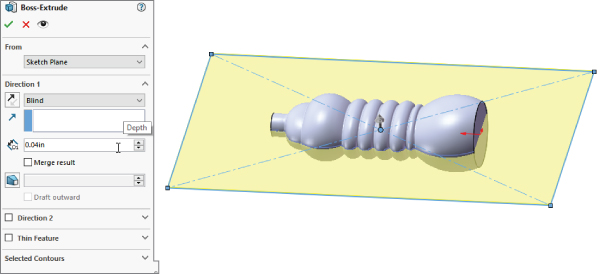
- Solution In the Chapter 8 Bottle part file, create a rectangular extrusion larger than the bottle, but only 1 mm or .0.025 inches thick. Make the new extrusion a different color to differentiate it from the bottle. Use the following graphic as a reference.
When you extrude the thin sheet, make sure the Merge option is turned off.
Use Indent, selecting the thin sheet as the Target, and select the half of the bottle that you want to be inside the cavity as the Tool body. Use the following graphic as a reference.
Make the thickness of the cavity 0.015″ to account for stretch, and leave a gap of 0.005″

Text often has to go on irregular surfaces. Work through this example to gain some experience putting it there.
- Master It In the downloadable file
Chapter 8 Tutorial Bracket Casting.sldprt, some text is wrapped onto one of the cylindrical bosses. Put a model number on the second boss using the same process. - Solution For this task, you need the sketch text and Wrap feature. Examine the existing Wrap feature to see how it was done, and repeat it with a six-digit model number on the other side.
Chapter 9: Patterning and Mirroring
Feature patterns and mirrors are powerful tools, but you must have some discipline to benefit from their usefulness. Patterns in particular are extremely flexible, with many types of functions and options available. You should avoid sketch patterns if possible, not only because of performance considerations, but also because complex sketches (sketches with lots of entities and relations) tend to fail more often than simple sketches.
- Master It Create an irregular sketch region on a flat face of a solid part of your choosing, add a hole inside the irregular region, and then use the Fill Pattern feature to fill the region with patterned holes.
- Solution Use the
Reference Fill Pattern.sldprtpart from the download material as a reference to examine how a fill pattern is made. - Master It Create a two directional linear pattern where the directions are not perpendicular to one another.
- Solution Use the
Reference Curve Driven Pattern Direction 2.sldprtfile as a reference to make sure you know how to control this type of pattern feature. - Master It Create a pattern feature and use the Instances to Skip to remove a couple of instances of the patterned feature.
- Solution Check the
Chapter 9 Solution Skip.sldprtpart from the download material for hints at the solution for this exercise.
Chapter 10: Using Equations
SolidWorks equations and related dimension-management tools are powerful. In the last several releases, they have been vastly updated. Even if you're not a huge equation user, the ability to build equations in the Modify and PropertyManager dimension boxes is a great convenience for such a powerful function.
Be careful about crossing SolidWorks native equation functionality with configurations; you may end up with dimensions that are controlled by both tools. Remember that the calculation capability of Excel is far greater than what is found in SolidWorks equations.
- Master It Equations and variables are keys to parametric design. Start simple by creating a rectangle with sides made equal by using the same variable name for vertical and horizontal dimensions.
- Solution
Chapter 10 Solution 1.sldprtholds the key. Edit the sketch and show the dimensions. You can enter the variable name right in the Modify box. To make the second one equal, type an equal sign where you would normally put the dimension value, and click the other dimension. This automatically makes an equation where the second dimension equals the first one. - Master It After you have created the rectangular sketch with equal sides, make the extrusion depth also equal so that no matter what size it is, the solid will always be a cube.
- Solution To do this, type an equal sign where you would normally type the extrusion depth in the PropertyManager, and then click the first dimension to which you assigned a variable; SolidWorks automatically makes the assignment.
Test this a couple of times by changing a dimension and watching the solid rebuild. Remember, you cannot change a dimension that is driven by an equation.
- Master It One of the most common situations in design is needing to spread out holes. Equations are a great way to do this. Study the part named
Chapter 10 Equations.sldprtand re-create it on your own. - Solution The key to this part is getting the pattern of holes correct, and then writing an equation that evenly spaces the holes, taking the end spacing into account.
Chapter 11: Working with Part Configurations
Configurations are a powerful way to control variations of a design within a single part file. Many aspects of a part can be configured, although a few cannot. Manually created configurations are useful for making a small number of variations and a small number of configurations, but they become unwieldy when you need to make more than a few variations of either type.
Using design tables to control design variations is recommended because you will be able to see more clearly all the changes you have made to all the configurations. Additionally, by having the power of Excel available, you will be able to access many functions that are not shown here, such as using lookup tables and Concatenate functions to build descriptions or configuration names.
- Master It Create a simple block from a fully dimensioned sketch, name all of the dimensions, and create three configurations such that each configuration changes one of the dimensions. Show all the dimensions on the screen.
- Solution Compare your part against the download file named
Chapter 11 Solution 1.sldprt. - Master It Take the part from the previous exercise and auto-create a design table, add 10 more configurations, with different dimensions in each, and configure a custom property called Vendor to have a different value in each configuration.
- Solution Compare your part against the download file named
Chapter 11 Solution 2.sldprt. - Master It Take the part from the previous exercise and add a feature to it. Use the design table to turn the feature on or off (unsuppressed or suppressed) in each configuration. Also change the part color in several configurations.
- Solution Compare your part against the download file named
Chapter 11 Solution 3.sldprt.
Chapter 12: Editing, Evaluating, and Troubleshooting
Working effectively with feature history, even in complex models, is a requirement for working with parts that others have created. When I get a part from someone else, I usually look first at the FeatureManager and roll it back if possible to get an idea of how the part was modeled. Looking at sketches, relations, feature order, symmetry, redundancy, sketch reuse, and so on are important steps in being able to repair or edit any part. Using modeling best practice techniques helps to ensure that when edits have to be done, they are easy to accomplish, even if they are done by someone who did not build the part.
Evaluation techniques are really the heart of editing, as you should not make too many changes without a basic evaluation of the strengths and weaknesses of the current model. SolidWorks provides a wide array of evaluation tools. Time spent learning how to use the tools and interpret the results is time well spent.
- Master It Set and test the following ease-of-use settings. Set and test the following settings to make sure you know where to find them and what they do:
- Arrow Key Navigation for the FeatureManager
- Flyout FeatureManager
- Selection Breadcrumbs
- Dynamic Reference Visualization
- Show Flat Tree
- Solution
- Tools ➢ Options ➢ FeatureManager ➢ Arrow Key Navigation
- Flyout FeatureManager is available when the PropertyManager obscures the regular FeatureManager
- Breadcrumbs display in upper-left of graphics window or at the cursor with the D hotkey.
- View ➢ User Interface ➢ Dynamic Reference Visualization
- RMB on the name of the part in the FeatureManager, and select flyout for Tree Display ➢ Show Flat Free
- Master It Use the part from the download material called
Horizontal.sldprt. This part uses several sketches to drive the entire part. Take a look through this part, and try to re-create one that is similar. - Solution Use the Rollback bar, Edit Feature, and Edit Sketch to compare your work against mine. Also use the Part Reviewer and Dynamic Reference Visualization.
- Master It Edit the previous part to see if you can make features fail. In particular, reorder some fillets. Next, try the same thing with the part called
Vertical.sldprt, which is provided with the download material. Examine the Vertical part and try to figure out why reordering the fillets causes so many failures. - Solution The Horizontal part will not allow you to edit it in such a way that it will fail. The Vertical part will fail when fillets are reordered, because so many dimensions and sketch relations are made from edges created by the fillets—hence, they have formed parent/child relations.
Chapter 13: Building Efficient Assemblies
Assemblies are more than simply parts and subassemblies put together with mate relationships; several other types of features and placeholders can also exist in the assembly FeatureManager. Organizing assembly components is fairly straightforward and can offer benefits for finding parts as well as controlling suppression and display states globally.
The assembly FeatureManager contains several options for the data to display for subassemblies, parts, configurations, metadata, and features within. Remember that all the data that you include in your SolidWorks documents can be accessed and reused later, so it's worth the effort to name it properly. Descriptions can be very important, both at the part level and also for features and configs.
- Master It Use SolidWorks Treehouse to establish the framework for a simple product with two layers of subassemblies. Add some custom properties to the documents that you might want to use to fill in a BOM. Use appropriate templates and save the documents to a special folder.
- Solution Use the data in the Solution1 folder contained in the download data to compare to your solution. You can use SolidWorks or Treehouse to open the existing files.
- Master It Speed is a huge part of building an efficient assembly. You measure speed with the Tools ➢ Evaluate ➢ Performance Evaluation tool. Open the Performance Evaluation tool while looking at an assembly (for example, the
Bike Finished.sldasm) and learn what you can about what types of features and techniques cost you the most rebuild or display regeneration time. - Solution The number of shaded triangles goes up for curved parts or parts with a lot of small detail. Your graphics card calculates display based on triangles. Settings such as Verification On Rebuild and Large Assembly Mode also influence rebuild times. Overall assembly statistics also have an effect, including total components, unique parts, number of bodies, subassemblies, number of mates, and so on.
- Master It Use the Assembly Visualization tool to sort the parts according to various criteria, and become more familiar with the information presented by Performance Evaluation.
- Solution Expand the PropertyManager area so you can see the names of all the parts, and then click on the column headers to sort the list by Rebuild Time and Open Time. Examine the similarities and differences between the order of parts. Also sort by Graphics Triangles, and notice the effect of Quantity. What would you have done differently in this assembly to make it open faster and take less time to rebuild?
Chapter 14: Getting More from Mates
A thorough understanding of mates (and their editing and troubleshooting techniques in particular) makes the difference between a real assembly artist and a user who struggles through or avoids certain tasks. Much about mates is not straightforward, but with practice you can understand and master them. You can put assemblies together quickly, with a focus on rebuild performance and Dynamic Assembly Motion.
Although best practice concepts should not dominate your designs, they are great guidelines from which to start. To avoid making big mistakes, watch out for the pitfalls outlined in the section in this chapter that summarizes mate best practices to follow.
- Master It SmartMates are a key to putting assemblies together quickly in SolidWorks. Practice using SmartMates in a single assembly window, and also between a part and assembly in tiled windows. Practice using the Tab key to flip the orientation of the mate.
- Solution Successful SmartMates will get a Coincident and a Concentric mate. Make sure you are getting the mates you intend, and use the cursor icons to convey that information.
- Master It Make sure you understand the function of mates. Go through a sample assembly and sort through the mates that prevent motion and the mates that enable motion. Put these mates into separate folders.
- Solution The mates shown with the ground symbol in the Mate folders under the parts are the ones that ground the parts. This is shown in the following graphic, and you can see them in action in the assembly named
Robot Assembly ground.sldasm.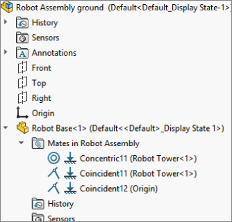
- Master It Work through several of the specialized mechanical mates and make sure you can use the sample assemblies to re-create the motion. Use the parts from the sample assemblies for each of the mates and reassemble the parts to have the intended motion.
- Solution Use the assemblies for Hinge, GearMates, CamMultipleFace, CamSingleFace, and LinearCoupler for this practice exercise.
Chapter 15: Patterning and Mirroring Components
Performance and best practice are both issues that require compromise. Patterns can cause a performance reduction because of the nature of the references. However, they can also improve performance because the need for extra mates is reduced, and it is easier to simplify the assembly by suppressing the pattern feature.
Feature-driven patterns are driven by feature patterns and transgress best practice suggestions, but they also add a parametric link, which updates the component pattern automatically. In addition, they offer many more options that are driven by the pattern options available to features in a part.
- Master It Create a new part with a feature pattern, then put that part in an assembly, and use the
Patterned Part.sldprtfrom this chapter and pattern it using a pattern-driven pattern. - Solution The solution should look like the tutorial example from this chapter.
- Master It Create a new assembly from a template that uses axes for the main X-, Y- and Z-directions. There is one called
AxesAssembly.asldotin the MBD template folder. Insert an assembly such as one of the sample bicycle wheel assemblies, and pattern it in three directions. - Solution You will have to use two separate Component Pattern features to accomplish this. The result (depending on how many patterns you make) may tax the display on your computer. Part of what you should learn from this chapter is that just because you can do something is not enough reason to do it. You need to consider performance when assemblies and patterns start to become large. The definition of “large” will be whatever number of components starts to tax your computer.
- Master It Create a new assembly, and open a new sketch in the assembly. Create a closed-loop sketch that is bigger than 6 inches on a side where all of the elements are tangent (no small fillets or tangent arcs between lines).
Create a curve-driven pattern that uses the
Patterned Part.sldprtto be patterned in two directions based on elements in the sketch.Copy the sketch to a perpendicular plane in the assembly and create a chain pattern using the same part and the Distance Pitch method in the Chain Pattern PropertyManager.
- Solution See the solution in the
Solution 3 pattern assembly.sldasmfile.
Chapter 16: Working with Assembly Sketches and Layouts
Laying out an assembly with reference sketches is a more disciplined way of working that can help you avoid some of the complications of external references and in-context design work. It is up to you to decide whether the informal 2D layout sketches are preferable to the formal 3D sketch-based Layout feature. Both offer tools to control positions of parts and even features of parts within an assembly.
Traditional assembly-modeling methods where each part is located by mates from another part do not stand up well against changes in the parts themselves. The main goals of the layout methods are centralization of control and stability of changes. I invite you to explore some of these methods using the tools you have learned in this chapter.
- Master It Use an assembly Layout to create a four-bar link and assign parts to the blocks in the Layout sketch. To remind you, the workflow for Layout is like this:
- Open the assembly.
- Click the Layout tool.
- Sketch three bars of differing lengths.
- Create three separate sketch blocks, one using each bar.
- Assemble the bars to create a four-bar link mechanism. (Yes, a four-bar link can have only three bars, the fourth bar is ground.) If you cannot see how to do this in a 3D sketch, refer to the downloaded example for this chapter for hints.
- Test the motion of the assembled link blocks.
- Exit the Layout.
- Create parts on each of the blocks.
- Use the sketches in the parts to create solid geometry for the bars.
- In the assembly, test the motion using dynamic assembly motion (dragging parts).
- Solution Refer to the
4-bar Link Layout solution.sldasmassembly in the download material for a working Layout assembly using a four-bar link. - Master It Use the assembly you created (or the downloaded example named
4-bar Link Layout solution.sldasm) to first rename and then save out the internal virtual parts so they are external, stand-alone parts. - Solution Rename the parts by right-clicking on that part and selecting Rename. To save the part to an external part file, use the RMB menu and click Rename, which is the next option down the list.
- Master It Edit the Layout from the previous exercise. Change the length of one of the links. This will involve first clicking the Layout tool, and then editing one of the blocks. When you exit the block, the layout sketch and then the solid geometry should both update. Perform a test by exiting the layout and making sure the motion is still correct.
- Solution Refer to the downloaded example file named
4-bar Link Layout solution.sldasmto confirm that you have done the work correctly.
Chapter 17: Using Assembly Tools
SolidWorks packs lots of powerful and useful tools into the assemblies environment. Even if you are an experienced user, it pays to look through the list now and then because new functions are added frequently, or you may have a new use for an old tool.
- Master It Open the assembly called
Bike.sldasmfrom the downloaded materials for this chapter. Use each of the tools in the Tools ➢ Component Selection list to practice selecting parts in the assembly:- Volume Select—Drag a rectangle and then drag it to create a solid volume.
- Select Suppressed
- Select Hidden
- Select Mated To
- Select Identical Components
- Select Internal Components
- Select By Size
- Solution Selected components are displayed in blue and shown in the Breadcrumb display and the FeatureManager.
- Master It Use Advanced Select to select any components where the configuration name is not Default. Then invert the selection (RMB on a highlighted item, and it should be the first selection in the list), and then suppress all of the nonconfigured items.
- Solution You could do this more easily if you changed the initial conditions of the select, but using Invert Selection is good practice. Notice that this suppresses all the instances of the chain pattern, so you will have to manually suppress the Chain Pattern feature separately.
- Master It Use one of the selection methods of your choice to select multiple components. Save the selection as a Selection Set.
- Solution With the components selected, right-click and select Save Selection from the list. This will add a folder to the Folder list at the top of the FeatureManager. If you clear the selection by clicking in blank space and then click the newly created Selection Set, the previously highlighted parts will be reselected.
Chapter 18: Using Libraries, Assembly Features, and Hole Wizard
Assembly features can be quirky and are often used for specialized or niche applications. Having this functionality available gives you another tool in your toolbox for solving design and documentation problems.
The Hole Wizard can be a useful tool for placing machined holes through multiple parts. Automation is a great thing, and you should utilize it where it helps your process.
- Master It The most basic step in reusing data in the form of libraries is establishing the location of your libraries. Use the settings at Tools ➢ Options ➢ File Locations to do this. First, determine if you need local (on your computer) or network locations for these libraries.
- Solution Settings can be copied to multiple machines via the Registry or the SolidWorks Settings Wizard. Select a location for your libraries where it won't be overwritten by SolidWorks while installing, reinstalling, or updating the software. It is also a good idea to keep the libraries off of the drives where the operating system is installed, so your computer can be recovered without losing any saved data if there is a crash.
- Master It Make sure you know where in your interface to find the Design Library and how to navigate its various elements.
- Solution Refer to Chapter 2, “Navigating the SolidWorks Interface,” to see how to access the Design Library.
- Master It Toolbox can be an integral part of using libraries with SolidWorks. Learning to manage Toolbox, however, may drive you to make the decision to create and manage your own library of standard parts. Make sure you have learned where the weaknesses of Toolbox are and how to work around those weaknesses.
- Solution Toolbox's main weakness is when you have multiple users or share Toolbox data with people who don't all have the same parts built. Because Toolbox builds parts as they are needed, some users may have parts that others do not. Also, one Toolbox user can have customizations that others with whom he or she shares data does not. Toolbox is a brilliant idea, but its ability to work around differences is limited. Make sure that you have your file management issues worked out, and that everyone works from the same libraries. The potential problem is that Toolbox will suppress hardware for which it does not have a match. You may even save assemblies in a state where your Toolbox data cannot be retrieved. Many companies use Toolbox to create the parts, but then rename them and store them separately in libraries. Using Toolbox with configurations can add to the confusion if you are not careful.
Chapter 19: Controlling Assembly Configurations and Display States
Display states in the assembly can save you lots of time because they change faster than configurations and offer more options for visualization, including mixed display modes. Assembly design tables can select display states and drive many other parameters in assemblies. Remember also that Modify Configurations and the Configuration Publisher work in assemblies as well as in parts. Assembly configurations are very powerful tools for product variations and performance, especially when combined with a SpeedPak.
- Master It List at least three of the reasons or conditions under which to use display states instead of configurations.
- Solution
- Display states should be used in assemblies instead of assembly configurations when you are controlling the visibility or appearance of components.
- Display states allow you to change between states more quickly than you can change between configurations.
- Display states also involve much less data than configurations. Display states can be linked to configurations.
- Master It List at least three reasons to use design tables when you're working with assembly configurations.
- Solution
- Design tables are an organized way to keep track of the contents of multiple configurations.
- Design tables centralize the control of configurations, which can sometimes be confusing because of all the different ways of driving them.
- Design tables also give you all of the automation, organization, and analytical power of Excel to arrange and drive the data being fed to your model.
- Master It Explain the difference between Hidden and Lightweight model states.
- Solution With a hidden model, there is no visual data, but all the parametrics are active. With lightweight, only the visual data is loaded, with no parametrics.
Chapter 20: Modeling in Context
Although in-context functions are powerful and seductive, you should use them sparingly. In particular, be careful about file management issues such as renaming parts and assemblies. The best approach is to use SolidWorks Explorer or the Save As command with both the parts and assemblies open.
In-context techniques, including the Layout feature, are the pinnacle of true parametric practice and enable you to take the concepts of design intent and design for change to an entirely new level.
- Master It The first step in being able to work fluently with external references is to be able to recognize, identify, and edit them. Select a part from the download materials for this chapter with external references, and use the skills you developed in this chapter and others to remove all of the external references without deleting sketches or features.
- Solution The tools used to edit external references are the Hide/Show Relations in sketches, the Edit Feature tools that show end conditions for features, and the List External Relations tools. You may also need to Edit Sketch Plane to accomplish this. As always, look for the -> symbol.
- Master It Sometimes mixing advanced techniques can lead to undesirable results. Name a couple of advanced techniques you need to be careful of when combining with in-context.
- Solution Motion, multiple contexts, configurations, multiple instances, circular references, etc.
- Master It Describe the differences and similarities between a broken reference and a frozen reference.
- Solution A broken reference cannot be fixed other than by deleting it. Broken references are created with the List External References box. Frozen features are created with the Freeze bar, similar to the Rollback bar. The similarity is that neither a broken or a frozen reference will update.
Chapter 21: Editing, Evaluating, and Troubleshooting Assemblies
You might create your work once in SolidWorks, but you are almost guaranteed to spend more time editing it than you did creating it. Because of that, you need to be even more adept at editing and evaluating your SolidWorks assembly than you are at creating it. SolidWorks has lots of tools to help you do this.
- Master It File management is one skill that doesn't relate to engineering or design, but all CAD operators must be experts. Mismanaging the file can mean you lose a lot of work—or worse yet, by mismanaging, you can create problems with the work that you don't realize until it's too late.
As an exercise, use the SolidWorks Pack And Go to make a zipped copy of an assembly that has in-context references. If possible, take the zip file to another computer with SolidWorks on it and open it up. Check to make sure all of the in-context references are still in-context (and not out of context).
- Solution Use the Performance Evaluation tool to look at the assembly before and after transfer to make sure all the external references are intact.
- Master It Sometimes it's easier to look at the big picture and the small detail separately. When you are working on getting Fillet34 to work just right, it's not always a convenient time to also be changing the overall structure of your product's assemblies and subassemblies.
To get some practice, use the SolidWorks Treehouse tool to create the assembly structure for one of your company's products or an automobile if you need a different idea. Get as detailed with it as you can with the time you have available.
- Solution Getting organized at the beginning of a project is often a key to success later. Organization helps you plan for various types of work that you know are coming. For example, you can't do stress analysis until all the components exist in CAD. You need drawings to get quotes from vendors.
Make sure that your Treehouse structure is detailed and accurate.
- Master It Efficiency is one of the most important qualities of processes, workers, and tools. Use the SolidWorks Performance Evaluation tools to look at the Bike assembly to evaluate which parts are costing you the most to open on your computer. Cost is often measured by rebuild time. Make a set of recommendations for remodeling the bike so that the design costs are lower.
- Solution For this exercise, design costs are measured by rebuild and editing time. Other factors such as open time, errors, display performance, and overall statistics must also come in to play.
Chapter 22: Working with Large Scale Design
SolidWorks has long been used for the design of equipment and components that go into buildings. With Large Scale Design, the software also works for the design of small plants and gridded structures. Walk-through capabilities give Large Scale Design users some animation capabilities, and the *.IFC export options allow users to share SolidWorks Large Scale Designs with other BIM software users.
- Master It Use Large Design Review to examine the
dump truck.sldasmmodel that is included with the download materials for this chapter. Also open the same model in standard SolidWorks and familiarize yourself with the differences between the two. - Solution Large Design Review or LDR is primarily a viewer that looks at SolidWorks assembly data in lightweight mode.
- Master It Again, use the dump truck model to make a walk-through. Use either the manual controls or the 3D sketch path to direct the walk-through.
- Solution Create a movie to finish the walk-through project.
- Master It Start a new part and open a new GridSystem feature. Lay out a three-story structure to hold processing equipment, where the spacing between the first two floors is 10 feet and the spacing between Floors 2 and 3 is 12 feet.
- Solution Save the end product and examine it with the View Grid Components tool.
Chapter 23: Animating with the MotionManager
If you keep your animation relatively simple, the MotionManager tools in SolidWorks Standard should produce adequate results in some situations. If you are using mates to drive motion, be sure to follow best practice recommendations for mates. If you are manually positioning parts, remember to place key points closer together if the motion curvature changes abruptly.
If you are making larger animations and the end product is just an AVI file, it's acceptable to break the animation into smaller bits. This makes each part of the animation much simpler to do, and work can even be delegated to other users or other machines for parallel processing. It may also be beneficial to use post-processing to add captions and narration to your movies; a few words of explanation might be valuable to viewers.
- Master It In a blank assembly, create a camera with a circular path that focuses on the origin. Save the assembly as a template, and then use that template to create an easy turntable animation of any assembly or part you put into that assembly.
- Solution Test this by making new assemblies with a single part or another assembly inserted into it. Yes, they will all be the same aside from the geometry of the part/assembly, but they can be created in seconds.
- Master It Using the large dump truck, make an animation of the bucket raising and lowering, with a second before the motion, a second between raising and lowering, and a second after the lowering. Try to use the tools for mirroring the path that you learned in this chapter.
- Solution Getting practice with the simple tasks will get you going on more interesting animations.
- Master It Use RealView settings if your hardware is capable. Save out an AVI movie or the previous animation. Make sure it plays back as you expect on your computer and at least one other computer.
- Solution Sometimes getting the video codecs straight on your computer is the key to viewing movies you have created in SolidWorks.
Chapter 24: Automating Drawings: The Basics
Getting your templates and formats correct creates an excellent opportunity to save some time with drawings by automating many of the common tasks using templates, predefined views, multiple formats, blocks, favorites, and linked custom properties. Setup becomes more important when you are administering a larger installation, but it is also important if it's just for yourself. One of the most important things you can do is to establish a file library and direct your Tools ➢ Options ➢ File Locations paths to the files. There's nothing quite as productive as having something that works right the first time and every time.
- Master It Create formats for size A and B drawings. Copy them from existing DXF or DWG data, and modify them for your needs. Save as
*.SLDDRTfile type.Use the title block functionality to create an editable block of manually filled-in annotation in the format.
- Solution Formats should have a border around the outside of the drawing area and a title block with text annotations.
- Master It Set up a drawing template with the custom properties such as Revision, DrawnBy, ReleaseDate, and other properties that you can use to automatically fill out fields on your title block. Also, place one predefined view and a couple projected views.
Make sure that you save an appropriately sized format with your template, such that the template is sheet size specific.
- Solution Test your template by putting a part onto it, to make sure it populates all the views and all the fields in the title block.
- Master It Create a second page format with simplified title block and place it in a two-page drawing template. Make sure you have stand-alone copies of the formats in case you have a situation where you need to update the formats in drawings.
- Solution Second drawing pages are often useful in assembly drawings, or package or process drawings where you have a large number of views or large-scale views.
Chapter 25: Working with Drawing Views
SolidWorks has the capacity to make many different types of views of parts. In addition to the tools for projecting views, custom views saved in the model document can be saved and used on the drawing. The associative nature of the drawing to the model helps ensure that drawing views, regardless of how unusual the section angle or view orientation, are displayed in the correct size, location, and geometry.
It's sometimes better to create some of the views that require sketches by pre-sketching. Utilize workflow enhancements when possible; for example, the automated workflow of the Broken-Out section works well, but forcing it to be a manual process makes it awkward to use.
- Master It Included with the downloads for Chapter 1, “Introducing SolidWorks,” you will find a folder full of document (part, assembly, and drawing) templates. Using Windows Explorer, sort the templates and copy the
*.drwdottemplates into the location specified at Tools ➢ Options ➢ System Options ➢ File Locations ➢ Document Templates. - Solution This should have been done already, but the need for templates in the correct location should be clearer now that you've made a lot of drawings in this chapter.
- Master It Use the Robot Arm assembly in the download data for this chapter to create a drawing that uses an alternate position view on the first page and drawing views of the individual parts on pages after the first one. Make sure to use a template with a special page 2 format.
- Solution There are a couple templates provided with second pages, and at least one template contains a stand-alone second page, in case it needs to be added at some point.
- Master It Create a new drawing, and place two views on it using separate parts (using the Model View tool). Next, rotate one view 90 degrees and align it with the second view.
- Solution There are two ways to rotate the view: one way would be to make a horizontal edge vertical, and the second way would be to use the Rotate View tool on the Heads-Up View toolbar. To align views, right-click inside the view border, select Alignment, select a method, and then click the view to which you want to align the first view.
Chapter 26: Using Annotations and Symbols
Annotations and symbols in SolidWorks have many options for connection, creation, alignment, and display. Recent releases have brought major improvements to text-box-driven annotations. Custom properties and hyperlinks enable the user to populate drawing annotations with content and links to content. Sharing styles in templates is a great idea for readily available note styles.
Blocks have several flexible uses and can be updated from external files across many documents. Their use to simulate mechanisms, piecing together schematics, and annotating drawings, in addition to the Belts functionality discussed in Chapter 3, “Working with Sketches and Reference Geometry,” make blocks one of the most flexible functions available.
- Master It Create a note that is typed in with mixed case, and use a centerline symbol (the symbol, not an actual centerline) in it, and a link to a custom property from the drawing.
- Solution The All Uppercase option can be found in the Note PropertyManager. The Symbol Library is also in the Note Text Format panel (behind the centerline symbol), and you can link to Properties from the icon to the left of the Symbol Library.
- Master It Create a style that simply adds bold to a note, and apply it to several notes that don't use bold. Save that style to an external file, create a new drawing using your favorite template, load the style into the template, and resave the template with the new style. Confirm that the new style has been integrated into the format by creating a new drawing with that template, creating a new note, and then applying that style to the note.
- Solution The steps for this should be self-evident, just going through the steps in a self-directed way should help solidify awareness of this functionality for the reader.
- Master It
- Create a blank drawing.
- Create a note with 10 to 15 words, and then force it to wordwrap with a width of 2 inches.
- Add a leader to the note.
- Make it a jogged leader.
- Copy the note and make multiple leaders for the copy.
- Use the various justification or alignment options for top, middle, and bottom align, as well as left, center, and right.
- Solution The point here is to gain a little dexterity with adding enhancements onto notes and getting them formatted the way you need to for local company drafting standards.
Chapter 27: Dimensioning and Tolerancing
The argument about how to set up and use dimensions on drawings is as old as the process of creating geometrical plans from which objects are built. It's often difficult to separate fact and best practice from opinion. Although I leave it up to you to decide these issues for yourself, this chapter is intended to help you understand how to create the type of drawing you want.
The biggest conflict in this subject arises over whether to place live model dimensions on the drawing or to allow the requirements of the drawing to specify which dimensions are placed where. I am by no means impartial when it comes to this question, but again, you must choose for yourself.
- Master It Create a drawing from the part called
Simple Part.sldprtin the download material for this chapter. In the front view, shown here, use the DimXpert to dimension the view.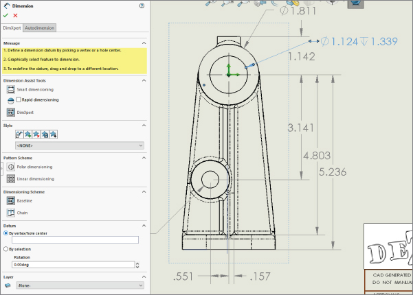
- Solution Initiate the DimXpert by clicking the Smart Dimension icon in the sketch or Annotation toolbar. Then follow these steps:
- Click the DimXpert button on the Dimension Assist Tools panel.
- On the Datum panel, click in the By Vertex/Hole Center box, and select the circumference of the big cylindrical boss at the top of the view. The green arrows should appear.
- Start clicking on features/edges of the part, and the DimXpert will add dimensions.
- Master It Use the Dimension palette to add text and tolerances to some of the dimensions.
- Add +/- 0.005 to the 5.236 dimension.
- Select one of the hole callouts and replace the depth with the word THRU. Use the Dimension PropertyManager to do this.
- Box select the 3.141, 4.803, and 5.236 dimensions and make them inspection dimensions.
- Solution The saved drawing
Simple Part Solution.slddrwshows the result. - Master It In the side view, use vertical ordinate dimensions to dimension some of the prominent features from that view.
- Solution It is best to turn on temporary axes or draw in axes for the cylindrical features to get started. To start the vertical ordinate dimensioning, click the Smart Dimension tool and make sure the Smart Dimension option is selected in the PropertyManager. Next, right-click, and under the More Dimensions flyout, select Vertical Ordinate. Select the bottom edge first, which will assign 0.
Chapter 28: Using Layers, Line Fonts, and Colors
Although SolidWorks is not primarily built around the strength of its 2D drawing functionality, it offers more capabilities than most users take advantage of. Layers, colors, and line styles can make your drawings clearer and easier to read.
- Master It Create a new drawing from the part called
Sample Casting.sldprtin the downloaded materials for this chapter. Make a drawing of it and import the dimensions automatically.Create a new layer called Dimensions and move all the dimensions to it using box select or the selection filter to help.
Set the color to the new dimension layer as dark blue.
- Solution You are starting to string together several automatic functions in SolidWorks. See how fast you can move through all of this data, and then imagine how long it would have taken on the drafting board.
- Master It Create several new annotations and place some blocks from the library.
Create a new layer for annotations and move these entities onto it.
Change the color of the new layer to dark green.
Leave the Annotations layer as the active layer and create a new annotation.
- Solution As you practice these workflows, the new tools will become second nature to you.
- Master It On the Sample Casting drawing, select a couple of interior edges and hide them using the Hide/Show Edges.
Next select a couple of exterior edges and change the line font to a thicker style.
- Solution Drawings give you the opportunity to communicate, and communication sometimes requires drawing someone's attention to a particular area. Using color and heavier lines are good ways to do that. With some of these new capabilities you have learned, you might consider using them to see if they help you make clearer drawings.
Chapter 29: Working with Tables and Drawings
SolidWorks enables you to work with tables that are highly specialized for particular uses and with general tables that are available for any type of tabulated data. The most frequently used types are BOMs, hole tables, and revision tables. Design tables that drive part and assembly configurations can also be placed on a 2D drawing, but in these cases, some formatting is usually necessary to make these tables presentable and the information on it easy to read.
- Master It Go through all of your drawing templates with formats, and all of your separate formats, and make sure that you have anchors for all of the table types your company creates.
- Solution The way to test this is to make new drawings with each template and place tables on them. Doing work ahead of time makes it so much more rewarding when the automatic setup pays a benefit.
- Master It Take an existing assembly drawing, add a column to it, add a property, and fill out the property values in the table.
- Solution Open one of the parts and check to see that the properties have been added.
- Master It Make sure the assembly has an exploded view, and make one view on the drawing show that explosion. Next, add balloons to the view, using at least two circular split-line balloons that show the item number as well as another value, such as the quantity, the weight, or a custom property value.
- Solution Attaching text (meta) information to graphical/geometric information is a great way to communicate quickly with people reading your drawings. Automatically supplying as much information in your drawings as possible will save you time and money, and it will help ensure that necessary information is on the drawing.
Chapter 30: Creating Assembly Drawings
Working with assembly drawings requires many of the same skills as working with regular drawings, but with much less dimensioning, and much more pictorial and visualization capability. Sometimes, you must use the unique tools for assembly drawings to get the job done.
- Master It Create an exploded view of one of the assemblies provided with the download materials for this chapter or one of your own. Draw in the explode lines.
- Solution The explode should show how the parts or subassemblies go together, and the explode lines should graphically connect corresponding points on mating parts.
- Master It Use a template with a second page to create a new drawing. I suggest the template called
Mastering 2pg B size.Create a drawing of the assembly for which you created an exploded view. The first sheet should be automatically populated with three standard views and an isometric.
Show the isometric view of the assembly in its exploded state and apply balloons to all the parts.
Place a Bill of Materials table on the drawing that shows item numbers for each balloon.
- Solution It should be self-evident if each of these steps is correct. If you are having problems figuring out where to find something, or how to make something happen, refer back to this chapter. Remember, a lot of tools can be found on the right mouse button menu, and SolidWorks is very context-sensitive, so having the right thing selected is important (view versus sheet versus geometry).
- Master It Starting with the drawing from the last practice exercise, switch to the second sheet. Click on the Standard 3 View icon on the View Layout tab. Select one of the parts from the assembly. If you have not opened any parts individually, you'll have to browse for it.
Place the views on the drawing and add an isometric view.
Put some custom properties in the part and make sure that the title block on the second page format picks up some of the part information.
- Solution Automation becomes its own reward when you start getting more out of it than you have to put into it. Learning some of the more advanced features in the software also pays off when you are able to accomplish more and more impressive tasks with a minimum of ongoing effort.
Chapter 31: Modeling Multibodies
Beginning to understand how to work with multiple bodies in SolidWorks opens a gateway to a new world of modeling possibilities. Like in-context design, multibody modeling is definitely something that you have to go into with your eyes open. You'll experience difficulties when using this technique, but you'll also find new possibilities that weren't available with other techniques. The key to success with multibody techniques is understanding the capabilities and limitations of the tools.
When using a model with the multibody approach, make sure you can identify a reason for doing it this way rather than using a more conventional approach. Also keep in mind the list of applications or uses for multibody modeling mentioned in this chapter. For some types of work, such as using the SolidWorks Mold tools and weldments, you cannot avoid multibody modeling.
- Master It Use the following methods to create multibodies within a part file:
- Multiple closed loops within a single Extrude feature
- Multiple disjoint features of different types within a single part
- Creating two solid features that merge to create a single body, then turning off the Merge Result option in the second feature to create a second body
- A Cut feature that separates a single body into multiple bodies
- Splitting a single body with a plane
- Solution The steps to perform each of these types of body creation are self-explanatory, but the real value here is just getting used to going through the steps and seeing the result.
- Master It Using one or more of the models created in the previous exercise, use the RMB tools from the bodies folders and the Display pane to perform the following functions to body-level geometry:
- Hide and Show
- Rename
- Change Color
- Apply Material
- Change Display State
- Make a Body Transparent
- Solution The steps to perform each of these types of body creation are self-explanatory, but the real value here is just getting used to going through the steps and seeing the result.
- Master It Starting with one of the parts you created in the first exercise, use Insert Part to pull one of the other multibody parts into the current one. Then use Insert Into New Part to push the current part into a new part. Notice how all the parts are listed as bodies when treated in this way. Next, use Combine to merge any bodies that are touching.
- Solution One way to run an interference check on bodies is to put the part into an assembly, and in the Interference Check, make sure the option is active to Include Multibody Part Interferences.
Chapter 32: Working with Surfaces
Surface functions have a wide range of uses other than for complex shape parts, but thinking about your models in terms of surface features requires a slightly different approach. Becoming comfortable with the terminology, and the similarities and differences between solids and surfaces, is the first step toward embracing surfacing tools for everyday work.
You can think of surfaces as being reference geometry—stand-alone faces that you can use to complete various tasks.
- Master It Sketch a rectangle and extrude it as a surface. Then close one of the open sides with a planar surface and knit together the two surface bodies. Next, use the Thicken tool to thicken the surface into a hollow box.
Notice the change from the count in the Surface Bodies folder to the Solid Bodies folder. Save the part.
- Solution A part created with these instructions can be found in the downloaded data for this chapter named
master it exercise 1.sldprt. - Master It Open the part saved in the previous exercise, and use Save As to make a copy of it with a new name.
Delete the Thicken feature.
Use a Fill feature to close the open side in the box, and use the options in the Fill feature to knit the part into a single surface body and make it solid.
- Solution A part created with these instructions can be found in the downloaded data for this chapter named
master it exercise 2.sldprt. - Master It Open the part used in the previous exercise and use Save As to save it with a new name.
Use the Move Copy Bodies command to make a copy of the solid body, and move the copy to one side so it does not touch the original.
Use Delete Face to delete one face of the new body. Notice that the solid body changes to a surface body.
Use a Loft surface to again close up the missing face, use Knit to knit it into a single surface body, and use Thicken to make it a solid body again.
Finally, use the solid Loft feature to loft between the two faces of the solid bodies that are closest to one another, and merge the result so there is a single solid body in the part.
- Solution A part created with these instructions can be found in the downloaded data for this chapter named
master it exercise 3.sldprt.
Chapter 33: Employing Master Model Techniques
Each of the four functions has strengths and weaknesses. The Insert Part feature is probably the most flexible of them, mainly because of the additional items you can bring forward from the parent document, and the fact that it can handle both solid and surface bodies. The Split feature also has unique strengths because of its ability to split bodies, save multiple bodies to files, and reassemble the parts as an assembly.
If you are working with surface bodies, you must use Insert Part or Insert Into New Part. Another important strength can be found in the Save Bodies feature, which makes the child accessible from the parent and identifies the assembly in the parent.
- Master It Leading up to master model techniques, you need to be proficient with body management. Master model is really just moving the body conversation to external files.
Name the four Master Model tools.
Name three body management tools.
- Solution The four Master Model tools are as follows:
- Insert Part
- Insert Into New Part
- Save Bodies
- Split/Create Assembly
The body management tools are as follows:
- Keep/Delete Bodies
- Rename Bodies
- Move Bodies
- Body folders
- Body appearances/materials/display style
- Feature Scope (list of bodies a feature affects)
- Show Feature History (for bodies)
- Merge Result
- Combine/Join/Cavity
- Intersect
- Master It Follow these steps:
- Open a new part, draw a centered rectangle centered on the origin, and extrude it mid-plane to make a block.
- Use the Split command and the three default planes to split the part into eight bodies. (Click the scissors to automatically select all the bodies for saving to parts.)
- Use Auto-Assign Names within the Split command to make parts for each body.
- Use the Create Assembly command (Insert ➢ Features) to create an assembly from the bodies created by the Split Command.
- Assign different appearance properties to each part in the assembly.
- Open the List External References for one of the bodies and locate the path to the original part.
- Use the Lock All button to lock references for this body. Notice that only the references for this body are locked. The rest of the external references are still functional.
- The locked external reference symbol −> * shows up on the locked part, but the rest of the parts still use the active external reference symbol −> . Check this by editing the Stock feature for both locked and unlocked parts.
- Solution Compare your results to the
master it exercise assembly.sldasmfile included with the download material for this chapter. - Master It Go back to the master model (the original part where the block was created) and follow these steps:
- Close all parts and assemblies other than the original master model.
- Using the Save As Copy and Continue option, save the master model with a new name. Then close the master model. Everything should be closed at this point.
- Open the new master model.
- Roll back before the Split feature and add fillets to all the corners of the part, and then roll back down after the Split feature. (The Split feature fails.)
- Edit the Split feature, recut the part with the three planes, and reassign names to all the bodies. Notice that SolidWorks avoids the previously created filenames. Make sure the Propagate Visual Properties option is selected. Exit the feature.
- Assign the colors in the part to the bodies this time, and the colors will propagate to the parts.
- Execute the Create Assembly step again, making a new assembly with the new master model.
- Use Isolate to edit each body in the new assembly and add a Shell feature that removes the inside faces. Do this for at least three of the parts.
- Change the size of the second master model, save it, and then switch to the assembly, which will update.
- Solution Compare your results to the
master it exercise assembly 2.sldasmfile included with the download material for this chapter.
Chapter 34: Using SolidWorks Sheet Metal Tools
SolidWorks offers a broad range of sheet metal tools to tackle most of your modeling situations. Some of the tools still require a little imagination to visualize real-world results because the complex shapes created in the real world where bends intersect are problems for such highly automated software. The tools are able to deal with imported or generically modeled geometry as well as parts created using the dedicated sheet metal tools.
- Master It There are three basic methods for working with sheet metal in SolidWorks: Base Flange, Insert Bends, and Convert Entities. We'll have one exercise for each method.
Follow these steps to build a basic Base Flange type part:
- Create a sketch like the one shown here.

- Use the Base Flange tool on the Sheet Metal toolbar to extrude the sketch midplane 4 inches, with a thickness of 0.025 inch.
- Add a flange to one of the open sides that matches the height of the tallest flange (use Up To Vertex). The defaults are an Inside Bend Radius of 0.029 inches, an angle of 90 degrees, and the flange position set to Inside. Turn on Custom Relief and use the Tear type.
- Put a Sheet Metal Gusset feature in the middle of the newly created bend. Here are the settings:
- Offset = 1.5″
- Indent Depth = 0.375″
- Flat Gusset, Edge fillet = 0.1″
- Indent Width = 0.500″
- Corner Fillets = 0.2″
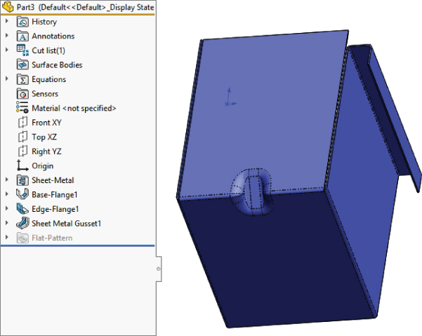
- Flatten the part to see the result.
- Create a sketch like the one shown here.
- Solution Check your completed part against the one in the download material for this chapter named
Chapter 34 - Master It 1.sldprt. - Master It The second Sheet Metal method uses Insert Bends. Let's make a part with that method.
- Copy the initial sketch from the last part and paste it on the Front plane of a new part. Edit the sketch and drag the point that appears to be at the origin away from the origin, and then drop it back onto the origin to make sure it picks up that relation. The sketch will turn from blue (underdefined) to black (fully defined).
- Extrude the sketch using the regular Extrude command (not the Sheet Metal Base Flange) using midplane, 4 inches, thickness 0.025 inch, material to the inside.
- Open a sketch on the base inside face of the part and convert entities on one of the edges at an open end. Drag the ends back and dimension them 0.125 inch from the edges.
- Extrude the open sketch up to the vertex of the shorter flange as shown in the following graphic. Set the thickness to 0.025 inch, and the material to the inside. (If the material goes to the outside, you will have edge-to-edge contact between the existing body and the new feature, which constitutes a zero-thickness edge and thereby produces a new body rather than merging with the existing body.)

- Use the Convert Insert Bends feature (this may not be on the toolbar by default, so use Insert ➢ Sheet Metal ➢ Bends if necessary). Set the Bend Radius to 0.30 inch and the Auto Relief to 0.50 inch. Accept the feature. This will give you the situation shown here.
- Use the edge flange to add a new flange on the remaining open end of the box. This doesn't seem like a big deal, but it combines new (Base Flange) and old (Insert Bends) methods for working with SolidWorks sheet metal.
- Flatten the part to make sure it is correct.
- Solution Check your completed part against the one in the download material for this chapter named
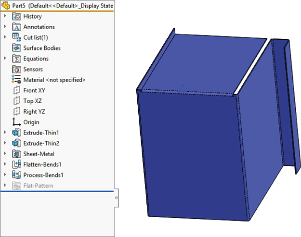
Chapter 34 - Master It 2.sldprt. - Master It The final Sheet Metal method is Convert To Sheet Metal. Follow these steps:
- Make a 3D box, 3 × 4 × 6 inches.
- Use the Shell feature to make it into a 0.025-inch thin wall part and remove one 6 × 4 face.
- Use the Convert To Sheet Metal feature with the following settings:
- Select the bottom face as the fixed entity.
- Select the four edges around the bottom face as bend edges.
- Under Corner Defaults, select Open Butt,0.05″ gap and 0.5 overlap ratio.
- For Auto Relief, use Tear with a 0.5 relief ratio.
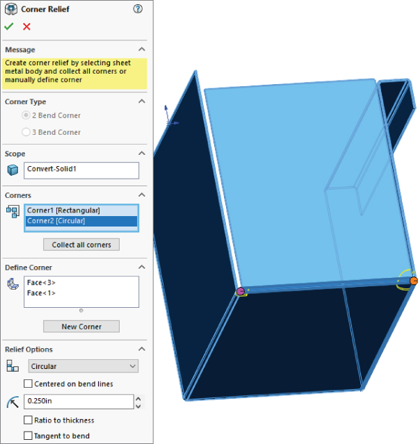
- Initiate a Corner Relief feature, as in the following graphic, with the following settings:
- Two bend corners
- Rectangular relief for all corners
- 0.1″ slot length
- Flatten the part to make sure it is correct.
- Solution Check your part against the completed part to check yours against is in the download material for this chapter named
Chapter 34 - Master It 3.sldprt.
Chapter 35: Creating Sheet Metal Drawings
SolidWorks has lots of special drawing functionality built around sheet metal parts. You may want to create a special template or format for sheet metal drawings or even use multipage drawings for including both flat and formed views of the part.
Multibody modeling in sheet metal opens another range of possibilities in documenting inseparable subassemblies and small weldments using sheet metal parts. The use of a cut list is similar to the use of a BOM, and though originally intended for weldments, it's also useful for sheet metal parts.
- Master It Create a blank drawing using a B-size template that has a second page (for example, the
Mastering 2pg B size.drwdot). Remove any predefined views.Create a flat-pattern-drawing view of the part
Chapter 35 - Master It 1 start.sldprt.Apply bend notes to the view.
Show bend lines without bend areas,
Show the bounding box on the flat pattern view.
On the second page, place an isometric view of the part, in Shaded With Edges mode.
Make sure the custom properties from the part have filled out the title block information.
Scale the isometric view at 2:1.
- Solution Check your drawing against the solution for this exercise in the download materials for this chapter called
Master It 1 finish.sldprt. - Master It Apply ordinate dimensions in horizontal direction for the major edges and baseline dimensions vertically.
- Solution Check your drawing against the solution for this exercise in the download materials for this chapter called
Master It 1 finish.sldprt. - Master It On the second page, place an isometric view of the part, in Shaded With Edges mode.
Make sure the custom properties from the part have filled out the title block information.
Scale the isometric view at 2:1.
- Solution Check your drawing against the solution for this exercise in the download materials for this chapter called
Master It 1 finish.sldprt.
Chapter 36: Creating Weldments and Weldment Drawings
Weldments are based on either a single 3D frame sketch or a set of 2D sketches, usually denoting the centerlines or edges of the various structural elements. This creates a special type of part in the same way that the Sheet Metal commands create a special type of part. Structural profiles are placed on the frame sketch to propagate and create individual bodies for the separate pieces of the weldment. Custom profiles are easily created as library features; you can add custom properties to the library features, and then the custom properties will propagate to the cut lists.
- Master It The first step in being able to model welded structures effectively is to have access to good libraries of structural section shapes. Whether you use the default installed libraries, use Toolbox libraries, or download individual structural shapes, building your library is key.
Move all of your library data into an area that is not affected by SolidWorks uninstalls or reinstalls—ideally, some location that would even survive an OS reinstall (i.e., not on your C: drive). You may want to have it on a network drive to share it with others. Hint: don't use mapped drives, instead use a UNC path such as
computer_nameshared_folder.Redirect SolidWorks to look for Weldment Profiles in the local or network location you have specified.
- Solution The file locations are set at Tools ➢ Options ➢ File Locations ➢ Weldment Profiles. Ideally, you should remove the old location and add the new location. You can add paths manually rather than by browsing by using the Edit All button, which enables text editing, so you can copy and paste paths from a list. These settings can also be copied through the Copy Settings Wizard and by editing the Windows Registry.
- Master It Build a picnic table using a custom profile (1.5 × 5.5).
- Solution Check your work against the model in the download material for this chapter called
Master It picnic Solution.sldprt. - Master It Create a drawing of the picnic table and add a cut list.
- Solution Check your work against the model in the download material for this chapter called
Master It Solution.slddrw.
Chapter 37: Using Imported Geometry and Direct-Editing Techniques
In recent years, Direct Editing tools have received lots of hyped press and marketing attention. However, CAD tools dedicated to working primarily as Direct Editing tools aren't going to overtake the tools used by professionals who design and model for production. If anything, they'll be used primarily by non-CAD specialists for simple editing and simple concept development, and possibly by downstream data consumers such as FEA analysts or CNC (Computer Numerical Control) machinists.
The Direct Editing tools available within SolidWorks are powerful and are becoming more powerful with each release. Although they may be best applied to imported data, they can also be applied to native SolidWorks data. This brings up questions of best practice and duplication of effort. Sometimes, the changes involved in editing a feature near the top of a long feature tree can be time-consuming compared to simply moving a couple of faces.
- Master It Familiarize yourself with existing import and export options. Use a model without errors for practice. If you have another CAD package available to you, use that for practice as well.
- Solution Export options are available at Tools ➢ Options ➢ Import/Export. Set the File Format to each type and examine the options available with each.
- Master It Open an assembly from one of the chapters on assemblies and export it. Then import it to see how it behaves and what you get. The practice of export/import is called a round trip. It is one way you can verify that the software has written good output data.
Be aware that importing an assembly will save automatically named part files on your hard drive. Make sure that the filenames are not overwriting or causing conflicts with other part files.
- Solution You must develop good file management practices with importing assemblies. Overwriting data is a danger of the automatic saving of parts.
- Master It The direct editing features are
- Move Face
- Delete Face
You can also perform any function that affects bodies rather than features.
Take the
Chapter 37 - casting direct edit.sldprtpart and practice removing fillets (using the Delete Face feature with the Delete and Patch option) without using any history-based tricks like rolling back or suppressing. Start with a simple loop like the filleted edges of the pie-shaped cut out in the web of the part.Remember that unlike true direct-editing CAD tools, SolidWorks leaves a history-based feature every time you use the Delete Face.
- Solution Use the example saved in the download materials as
Master It Solution Fillet.sldprtfor reference.
Chapter 38: Using Plastic Features
SolidWorks provides a vast amount of plastics functionality. The more you use these features, the more power you'll find in them. They'll become second nature after you've used them for a while. The power and flexibility are amazing when you think of the incredible range of parts that you can make and evaluate with these features. Automated functions aren't the answer to all problems, however. You need to be well versed in workaround techniques for more complex situations.
- Master It Follow these steps to create matching mounting bosses:
- Create a new part, and extrude a solid box using the Midplane option, with the size of the box at least 4 × 4 × 4.
- Use the Shell feature to hollow the box out with a wall thickness of 0.1″, without selecting a face to remove.
- Use the Intersect feature and select the solid body and the original sketch plane to create two separate bodies. Make sure to turn off the Merge Result option. You want to keep the outer two shelled bodies so you are left with two halves of an open box.
- Sketch a circle on a face of the block parallel to the split plane, as shown here.
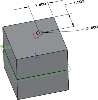
- Initiate a mounting boss, using the circle to locate the boss, and an edge perpendicular to the split as the direction.
- Select Hardware Boss type and the Head option. Other options are shown in the following graphic. You cannot go back to change the boss from Hardware Boss to Pin Boss later.
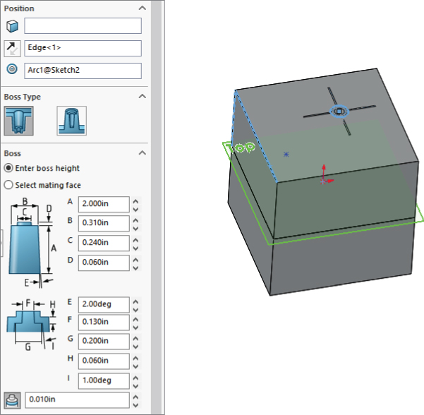
- Use the settings in the preceding graphic for the fins. Make sure you use a model edge to fix the direction of the fins.
- Accept the Mounting Boss options.
- Apply a section view so you can see the inside of the boxes and still see the mounting boss.
- Start the Mounting Boss feature again. Select the face opposite the original mounting boss face to put the new boss on. Select a circular edge of the first boss to locate the new boss. Select the Hardware Boss, Thread type as shown in the following graphic. Use a flat mating face to specify the length.

- Determine the direction of the fins of the second boss and accept the second Boss feature.
- Save the part.
- Solution You can use the part called
Master It Boss.sldprtin the download data for this chapter to check your work. - Master It Open the part you created in the previous Master It exercise and prepare to add a Lip/Groove feature to it.
- Use the Save As functionality to rename the part to
Master It Lip-Groove.sldprt. - Use the tool tips in the Lip/Groove Property Manager shown here for each selection box to make proper selections for the lip (add material) and groove (remove material).
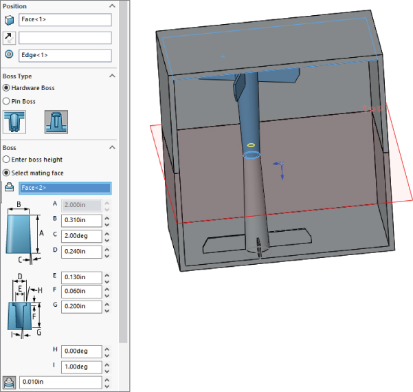
- The visualization may be difficult for this feature, but with a multibody part, SolidWorks temporarily hides the appropriate body at the appropriate time to allow you to make the selections.
- Use the Save As functionality to rename the part to
- Solution Examine the part in the download materials for this chapter to check your work.
- Master It The Undercut Analysis tool has been incorrect since it was added to the software. It's a little embarrassing considering the fact that the rest of the software is generally pretty good. It's like it was developed by someone who didn't understand the concept at all. Your mission, should you choose to accept it, is to write an enhancement request to SolidWorks to get them to fix this tool using either my suggestions earlier in the chapter or your own suggestions.
- Solution Submit your enhancement requests to the following website:
https://customerportal.solidworks.com/SWSearch/search.aspx?src=er&SRN=
Chapter 39: Using Mold Tools
SolidWorks Mold tools establish a method you can use for the semiautomated tasks involved in creating parting line, cavity, core, and parting surface entities and even pins, pulls and slides. For more involved nonplanar parting lines, you will probably want to intervene manually, which will call on your skills with surfaces, bodies, and visualization.
- Master It Understanding the draft analysis is the first real skill you need to have to create mold geometry in SolidWorks—aside from being able to create drafted parts, of course.
- Open the downloaded part named
Chapter 39 - Master It start 1.sldprt. - Run a draft analysis on it with the draft angle set to 1 degree and using the Face Classification setting. Face Classification counts the numbers of each type of face (positive, negative, requires draft and straddle—needs to be split). The Draft Analysis button stays depressed after you exit the command so that it retains the colors (rather than actually changing face colors). While in this mode, you can still work on the model, and additional features will be draft analyzed as well.
- To exit this mode and set the colors back to model color, turn off the Draft Analysis icon in the Mold Tools toolbar. Save the model.
- Open the downloaded part named
- Solution The positive or negative is determined by what you select as the direction of pull reference. In this case, 6 faces are drafted in a positive direction, 40 in a negative, and 0 each in the Requires and Straddle Faces classifications.
Open the part
Chapter 39 - Master It draft analysis.sldprtto check your results. - Master It Starting from where you left off in the previous exercise, follow these steps:
- Use the SolidWorks Mold tools to add the Mold folders to the FeatureManager.
- Expand the Surface Bodies folder to make sure it has subfolders called Cavity Surface Bodies, Core Surface Bodies, and Parting Surface Bodies.
- Initiate the Parting Line command and use the same Pull Direction reference as you did for the draft analysis previously. Set the draft angle to 1 degree and click the Draft Analysis button.
- Examine the part to make sure that the face coloring hasn't changed.
- Notice that SolidWorks has identified a parting line with 13 entities, and that the message at the top of the PropertyManager is yellow (the warning is shown in the following graphic).
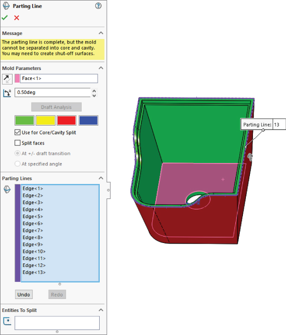
- Accept the feature and initiate the Shut Off tool.
- The shut-off may identify both the top and the bottom of the hole as shut-offs, but they will be identified as redundant. You need only one shut-off for this part. The shut-off edge needs to have all red faces on one side and all green faces on the other. So, you should delete the edge that has the same color on both sides. The PropertyManager message should read “The mold is separable into core and cavity” and be in a green field.
- Accept the feature and save your model.
- Solution Compare your model against
Chapter 39 - Master It shut off.sldprtto check your results. - Master It To finish this simple mold, you need to create a parting surface and split the cavity/core block.
- Initiate the Parting Surface tool. Set the Distance to 4 inches. Your model should look like the following graphic. This is a relatively simple nonplanar parting line, and SolidWorks gets this one correct.

- Initiate the Tooling Split tool and select the big flat face of the parting surface.
- Sketch a square centered on the hole, 6 inches on each side, and exit the sketch.
- Set the block size to 4 inches, and do not use the Interlock option.
- Use F8 to show the Display pane, and expand the Solid Bodies folder and the Parting Surface Bodies folder.
- Make sure to turn off the Draft Analysis mode at this point.
- Designate the top mold as Insert Body and the parting surface as Wireframe, and hide the cavity and core surface bodies as well as the original part.
- Initiate the Parting Surface tool. Set the Distance to 4 inches. Your model should look like the following graphic. This is a relatively simple nonplanar parting line, and SolidWorks gets this one correct.
- Solution Compare your model against
Chapter 39 - Master It split.sldprtto check your results.