
Chapter 32
Working with Surfaces
With surface modeling, you build a shape face by face. Faces made by surface features can be knit together to enclose a volume, which can become a solid. With solid modeling, you build many faces at once in a single feature to make the volume. In fact, solid modeling is really just highly automated surface modeling. Obviously, there's more detail to it than that, but this definition will get you started.
You can drive a car without knowing how the engine works, but you cannot get the most power possible out of that car by only pressing harder on the gas pedal; you have to get under the hood and make adjustments with an understanding of how it works. In a way, that is what working with surfaces is really all about—getting under the hood and tinkering with the underlying functionality.
The goal of most surface modeling is to finish with a solid. Some surface features make faces that will become faces of the solid, and some surface features only act as reference geometry. Surface modeling is inherently multibody modeling because most surface features don't merge bodies automatically.
Introducing Surfaces
In the end, you may never really need surfaces. You can perform workarounds using solids to do most of the things you need to do. However, many of these workarounds are inefficient, cumbersome, and raise as many difficulties as they solve. Although you may not view some of the typical things you now do as inefficient or cumbersome, after you see the alternatives, you may change your mind. The goal for this chapter is to introduce surfacing functions to those of you who don't typically use surfaces. I'm not showing how surfaces are used in the context of creating complex shapes—just how you can use them for various general 3D modeling tasks.
The word surfacing has often been used (and confused) to signify complex shapes. Not all surface work is done to create complex shapes, and many complex shapes can be made directly from solids. Many users think that because they don't make complex shapes, they never need to use surface features. This chapter shows mainly examples that don't require complex shapes, in situations where surfaces make it easier, more efficient, or simply possible to do the necessary tasks.
Although some of the uses of surfaces may not be immediately obvious, by the end of this chapter, you should have enough information and applications that you can start experimenting to increase your confidence in surfacing techniques.
Many surfacing techniques have some sort of equivalent or analog in the solid modeling world, but not all. When the analog does exist, I'll share it to help you understand the function of specific surfacing tools.
Understanding Surfacing Terminology
When dealing with surfaces, you may hear different terminology from the terminology typically used with solid modeling. This special terminology also often exists for surfaces because of important conceptual differences between how solids and surfaces are handled.
These terms are fairly universal among all surfacing software. The underlying surface and solid construction concepts are generally uniform between the major solid and surface modeling packages. What varies from software to software is how the user interacts with the geometry through the software interface. You may never see some of these terms in the SolidWorks menus, Help files, training books, or elsewhere, but as you use the software, you'll see why the concepts are relevant.
Exploring the Knit Function
![]() The Knit function is analogous to the solid feature Combine in that it joins multiple surface bodies into a single surface body. Unlike Combine, Knit doesn't perform the subtract or intersect Boolean operations. It also has an option to create a solid if the resulting surface body meets the requirements (a fully enclosed volume without gaps or overlaps). However, unlike the solid bodies in Combine, which may overlap volumetrically, surface bodies must only intersect edge to edge, more like sketch entities that can only touch end to end.
The Knit function is analogous to the solid feature Combine in that it joins multiple surface bodies into a single surface body. Unlike Combine, Knit doesn't perform the subtract or intersect Boolean operations. It also has an option to create a solid if the resulting surface body meets the requirements (a fully enclosed volume without gaps or overlaps). However, unlike the solid bodies in Combine, which may overlap volumetrically, surface bodies must only intersect edge to edge, more like sketch entities that can only touch end to end.
Knit is also sometimes used in the same way that the zero-distance offset is used, to copy a set of solid faces to become a new surface body.
You can find one nice option that enables you to quickly see where the boundaries of a surface body lie by choosing Tools ➢ Options ➢ Display/Selection ➢ Show Open Edges Of Surfaces In Different Color. By default, this color is a medium blue, and you can change it by choosing Tools ➢ Options ➢ Colors ➢ Surfaces ➢ Open Edges.
Using the Trim Function
![]() The Trim function in SolidWorks is analogous to the solid Cut. You can use sketches, planes, or other surface bodies to trim a surface body. The underlying surface is defined by a two-dimensional mesh, and for this reason, it's usually four-sided, like a woven piece of cloth, but may be other shapes. When the underlying surface is trimmed, the software still remembers the underlying original boundaries, but combines it with the new boundary, which is typically how face shapes (especially non-four-sided shapes) are created.
The Trim function in SolidWorks is analogous to the solid Cut. You can use sketches, planes, or other surface bodies to trim a surface body. The underlying surface is defined by a two-dimensional mesh, and for this reason, it's usually four-sided, like a woven piece of cloth, but may be other shapes. When the underlying surface is trimmed, the software still remembers the underlying original boundaries, but combines it with the new boundary, which is typically how face shapes (especially non-four-sided shapes) are created.
When you trim a surface, you can choose to delete either side of the Trim tool. With a mutual trim, both surfaces can be trimmed. A mutual trim usually leads to a corner created by the intersection of two surfaces.
Using the Untrim Function
![]() The Untrim function is predictably the opposite of Trim. It removes the boundary from a surface. Untrim restores the natural four-sided boundary that was changed by being trimmed by adjacent surfaces. Untrim can remove the boundary selectively (one edge at a time, interior edges only, and so on) or remove all the edges at once. Untrim even works on imported geometry, as described in the tutorial in Chapter 31, “Modeling Multibodies.” Figure 32.1 shows how Untrim works.
The Untrim function is predictably the opposite of Trim. It removes the boundary from a surface. Untrim restores the natural four-sided boundary that was changed by being trimmed by adjacent surfaces. Untrim can remove the boundary selectively (one edge at a time, interior edges only, and so on) or remove all the edges at once. Untrim even works on imported geometry, as described in the tutorial in Chapter 31, “Modeling Multibodies.” Figure 32.1 shows how Untrim works.

FIGURE 32.1 Untrimming a surface
Untrim works on native and imported geometry. It isn't truly like feature history in imported geometry, but it does help to uncover the underlying original shape of the face.
Hybrid Modeling
The term hybrid modeling can take on a lot of different connotations. You can have a mix between solid and surface, surface and subdivision, history and direct. So be careful when using the term; it means different things to different people. In this case, I’m using it to mean a combination of solid and surface modeling.
Surface modeling tends to be slower than solid modeling because you model each face individually and then manually trim and knit. Cutting a hole in a surface model is much more involved than cutting a hole in a solid. To cut a hole in a surface model, you first trim a hole on one side, then the other side, then make the cylindrical face of the hole, and then knit together the new and old faces as a single, enclosed volume.
Solid modeling is essentially highly automated surface modeling; however, as any software user knows, automation almost always comes at the expense of flexibility, and this situation is no different. Surface modeling puts the compromised power back into your hands, and that's really why we take the time to learn it.
Solid modeling strengths are predisposed to a type of part with square ends or a flat bottom because solids are creating all sides of an object at once, and capping off a solid feature with a domed shape is difficult. For example, think about an extrusion: Regardless of the shape of the sketch, you have two flat ends. Even lofts and sweeps typically end up with one or two flat ends because the section sketches are often planar. Surfaces enable you to create one side at a time. Another way of looking at it is that using surfaces requires you to build parts in sections.
Sometimes, you'll find that, even with prismatic modeling, surfacing functions are extremely useful. I don't propose that you dive into pure surface modeling just to benefit from a few of the advantages, but I do recommend that you consider using surface techniques to help define your solids when appropriate. This hybrid approach is sensible and opens up a whole new world of capabilities. I have heard people say after taking a SolidWorks surfacing class that they would never look at CAD geometry in the same way again.
Understanding Non-Uniform Rational B Spline
Non-Uniform Rational B Spline (NURBS) is the technology that most modern mechanical design modelers use to create 3D geometry. NURBS surfaces are defined by curves called isoparameter lines in perpendicular directions (referred to as U and V directions), which form a two-directional cloth-like mesh. The fact that perpendicular directions are used means that the surfaces have a tendency to be four-sided. Of course, exceptions exist, such as three-sided or even two-sided patches. Geometry of this kind is referred to as degenerate because one or more of the sides has been reduced to zero length. Degenerate geometry is often, but not always, the source of geometrical errors in SolidWorks and other CAD packages.
Figure 32.2 shows some surfaces with the mesh displayed on them. You can create the mesh with the Face Curves sketch tool.
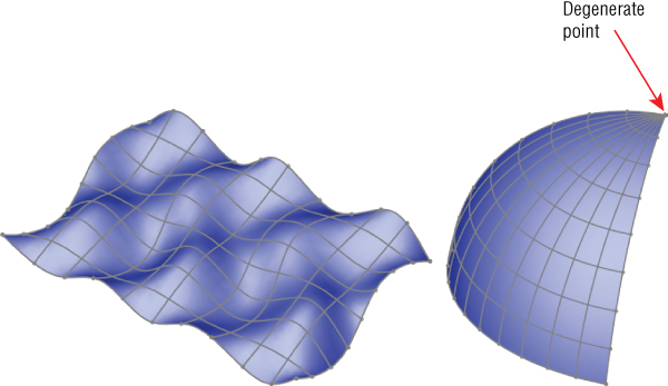
FIGURE 32.2 Meshes created with the Face Curves sketch tool
Using Developable Surfaces
Developable surfaces can be flattened without stretching. They are also surfaces that you can extend easily in one or both directions. These include planar, cylindrical, and conical shapes. It isn't a coincidence that these are the types of shapes that can be flattened by the Sheet Metal tools.
Using Ruled Surfaces
Developable surfaces are a special type of a broader range of surface called ruled surfaces. SolidWorks has a special tool for the creation of ruled surfaces, which is described in detail in the next section. Ruled surfaces are defined as surfaces on which a straight line can be drawn at every point. A corollary to this is that ruled surfaces may have curvature in only one direction. Ruled surfaces are far less limited than developable surfaces, but they aren't flattened as easily.
Ruled surfaces are used frequently in plastic parts and plastic mold design where draft and parting surfaces from 3D parting lines are needed.
Defining Gaussian Curvature
Gaussian curvature is not referred to directly in SolidWorks software, but you may hear the term used in more general CAD or engineering discussions. It can be defined simply as curvature in two directions. As a result, a sphere would have Gaussian curvature, but a cylinder would not.
Surfacing Tools
Surface feature equivalents are available for most solid features such as Extrude, Revolve, Sweep, Loft, Fillet, and so on. Some solid features don't have an equivalent, such as the Hole Wizard, Shell, and others. Several surface functions don't have solid equivalents, such as Trim, Untrim, Extend, Thicken, Offset, Radiate, Ruled, and Fill.
Using the Extruded Surface
![]() The Extruded Surface feature works exactly like an extruded solid, except that the ends of the surface aren't capped. It includes all the same end conditions, draft, contour selection, sketch rules, and so on that you're already familiar with. Figure 32.3 shows the PropertyManager for the extruded surface.
The Extruded Surface feature works exactly like an extruded solid, except that the ends of the surface aren't capped. It includes all the same end conditions, draft, contour selection, sketch rules, and so on that you're already familiar with. Figure 32.3 shows the PropertyManager for the extruded surface.

FIGURE 32.3 The Extruded Surface PropertyManager
You can create extruded surfaces from open or closed sketches, with open probably being the most popular type.
When two nonparallel lines are joined end to end in the same sketch, the result of extruding the sketch is a single surface body that's made of two faces with a hard edge between them. If the sketch lines were disjointed, the extrude would result in disjoint surface bodies. If the sketch lines were again made end to end, but done in separate sketches, the resulting surface bodies would be separate bodies; the second body would not be automatically knit to the first one as happens with the way solid features merge. This is an important quality of surfaces to keep in mind. If you create surfaces in different features and want them knitted into a single body, then you have to do that manually.
If you have a split line on a surface, you can select the surface and start the Extruded Surface command. You will then need to select a plane or axis to define the extrusion direction, and specify the depth of the extrusion. Figure 32.4 shows the PropertyManager and result of this function.

FIGURE 32.4 Extruding a 3D surface
This technique is special because of the additional options: Cap End, Delete Original Faces, and Knit Result. It would be nice for these functions to exist with regular sketch-based extrudes and other surface features as well.
You can find a similar function in the Surface Extrude's ability to extrude a 3D sketch. You can also use a regular Solid Extrude to extrude a 3D sketch, and it will cap the ends for you. I find all these extrude options interesting, but I have yet to find an application for them. The ability to extrude a 3D surface duplicates the Ruled Surface, although the additional options must be selected manually.
Using Boundary Surface
![]() The Boundary Surface feature was created as a higher-quality replacement for the Loft feature, but certain limitations mean that Loft has not been removed from the feature list. The Boundary Surface feature most resembles a loft, but it has elements of the sweep and fill. Loft also does a few things that Boundary cannot, such as a closed loop loft without a direction 2 curve, and most importantly, a centerline loft. Boundary Surface can use sketches, curves, or edges in several arrangements, such as curves arranged in an X, F, E, T, L, and other shapes. Figure 32.5 shows some of these shapes.
The Boundary Surface feature was created as a higher-quality replacement for the Loft feature, but certain limitations mean that Loft has not been removed from the feature list. The Boundary Surface feature most resembles a loft, but it has elements of the sweep and fill. Loft also does a few things that Boundary cannot, such as a closed loop loft without a direction 2 curve, and most importantly, a centerline loft. Boundary Surface can use sketches, curves, or edges in several arrangements, such as curves arranged in an X, F, E, T, L, and other shapes. Figure 32.5 shows some of these shapes.

FIGURE 32.5 Using different curve arrangements with the Boundary Surface feature
If several edge or sketch segments combine to form a curve in one direction, then you must use the SelectionManager to form the edge segments into a group. SelectionManager enables you to select portions of a single sketch or to combine elements such as Sketch, Edge, and Curve into a single selection for use as a profile or guide curve for Boundary or Loft features.
The interface for the Boundary Surface is shown in Figure 32.6.

FIGURE 32.6 The Boundary Surface PropertyManager
The main advantage of Boundary Surface over Loft is that Boundary Surface can apply a curvature boundary condition all the way around, while Loft cannot apply curvature continuity across the guide curves. I default to Boundary Surfaces when possible. Boundary Solid features are also available.
Using the Offset Surface
![]() The Offset Surface feature's closest relatives are the Thicken feature and the Sketch Offset. It may also fail for the same reasons. For example, if you offset a .25-inch radius arc by .3 inches to the inside, it will fail because it cannot be offset up to or past a zero radius. The same is true of offsetting surfaces. Complex surfaces don't have a constant curvature; they're more like a spline by having a constantly changing curvature. If the offset is going in the direction of decreasing radius and is more than the minimum radius on the face or faces being offset, then the Offset Surface feature will fail.
The Offset Surface feature's closest relatives are the Thicken feature and the Sketch Offset. It may also fail for the same reasons. For example, if you offset a .25-inch radius arc by .3 inches to the inside, it will fail because it cannot be offset up to or past a zero radius. The same is true of offsetting surfaces. Complex surfaces don't have a constant curvature; they're more like a spline by having a constantly changing curvature. If the offset is going in the direction of decreasing radius and is more than the minimum radius on the face or faces being offset, then the Offset Surface feature will fail.
One of the ways to troubleshoot a failing Offset Surface is to use the Check tool to check for minimum radius. Remember that the area with the minimum radius is a problem only if the curvature is in the same direction as the offset. If a small radius will increase when it's offset, then that small radius isn't the problem. The problem comes from the other direction where you are offsetting to the inside of a small radius.
Unlike the Sketch Offset function—and as shown in Chapter 31—you can offset surfaces by a zero distance. This is usually done to copy either solid or surface faces to make a new surface body. Zero-distance offset and Knit are sometimes used interchangeably, although Knit causes a problem if you are selecting a surface body that's composed of a single face. Knit assumes that you're trying to knit one body to another, so by default, it selects the body and then fails with the message that you cannot knit a body to itself. Because Knit has this limitation, and Offset doesn't, I prefer the Offset tool when copying faces to make a new surface body. You may also notice that when you enter a zero for the offset distance, the Offset PropertyManager name changes automatically to Copy Surface.
Knit does have two functions that Sketch Offset does not. One of them is the option to create a solid from the knit body if it forms a closed body. The second option is somewhat more obscure, offering the ability to select all faces on one side of a Radiate Surface. I discuss this option in more depth later in this chapter in the “Using Knit Surface” section.
When talking about copying surface bodies, you must also consider the Move/Copy Bodies feature, described in Chapter 31. When you’re simply copying a body without also moving it, this feature issues a warning that asks whether you really intend to copy the body without moving it. This is an annoying and pointless message. Also, the Move/Copy Bodies feature doesn't enable you to copy only a part of a body (selected faces) or to merge multiple bodies into one like the Knit and Offset Surface features.
All things considered, I recommend using the zero-distance Surface Offset feature to copy bodies or parts of bodies unless your goal is to immediately make a solid out of it (in which case, you should use the Knit feature) or when using a Radiated Surface (typically in a mold-building application).
Using Radiate Surface
![]() The Radiate Surface feature isn't one of the more commonly used surface features. It has been largely superseded by the Ruled Surface. This is because Ruled Surface does the same sort of thing that Radiate Surface does—and more. Radiate works from an edge selection, a reference plane, and a distance. The newly created surface is perpendicular to the selected edge and parallel to the selected plane and is the set distance wide. It's probably most commonly used in creating molds or other net shape tooling such as dies for stamping and forging, blanks for thermoforming, and so on. Figure 32.7 shows the PropertyManager and selection for creating a Radiate Surface.
The Radiate Surface feature isn't one of the more commonly used surface features. It has been largely superseded by the Ruled Surface. This is because Ruled Surface does the same sort of thing that Radiate Surface does—and more. Radiate works from an edge selection, a reference plane, and a distance. The newly created surface is perpendicular to the selected edge and parallel to the selected plane and is the set distance wide. It's probably most commonly used in creating molds or other net shape tooling such as dies for stamping and forging, blanks for thermoforming, and so on. Figure 32.7 shows the PropertyManager and selection for creating a Radiate Surface.

FIGURE 32.7 The Radiate Surface PropertyManager
The one application where the Radiate Surface has a very interesting usage is when you combine it with the Knit function. Figure 32.8 shows a part surrounded by a Radiate Surface (shown here in wireframe) in which the Knit feature is being used to select all the faces to one side of the radiated surface. The second smaller selection box in the PropertyManager that contains Face<1> is called a seed face and causes the Knit to automatically select all the faces on the same side of the model as the selected seed face. The requirement here is that the Radiate goes completely around the model and separates the faces into faces on one side of the Radiate and faces on the other side of the Radiate. The use of the Radiate with the Seed Face selection is extremely useful for mold creation.

FIGURE 32.8 Using Radiate Surface with Knit
Using Knit Surface
![]() The Knit Surface functionality was discussed previously in the “Understanding Surfacing Terminology” section as well as in the “Using Radiate Surface” section.
The Knit Surface functionality was discussed previously in the “Understanding Surfacing Terminology” section as well as in the “Using Radiate Surface” section.
If the knit operation results in a watertight volume, the Try To Form Solid option turns the volume into a solid. You can also make a solid from a surface using three other functions. The Fill Surface feature has an option to merge the fill with a solid or to knit it into a surface body; if the knit surface body is closed, then it gives you the option to make it a solid. This is a very nice, complete interface design, with options that save you many steps. The Fill Surface feature is described in more detail later in this chapter.
Create Solid is available only when you use Knit Surface or Fill Surface. Whenever you want the surface to become a solid body using Fill or Knit Surface, Create Solid highlights but remains inactive until all the surfaces are merged together and create a closed volume. Create Solid only highlights when you check Merge Result.
The Gap Control panel, shown in Figure 32.9, shows the gap between the edges of surfaces to be knit and enables you to see the gaps in a certain range and force gaps of less than a specified tolerance value, called the Knitting Tolerance, to knit.

FIGURE 32.9 Knitting surfaces with gaps using tolerances
With all powerful tools, the possibility of misusing those tools always exists. The ability to play with tolerances is a double-edged sword. On one hand, it gives you the ability to force surfaces to knit that may have otherwise not knit at all, by making the model tolerate larger gaps in defining solids or knitting surfaces. SolidWorks may force together surfaces or edges that have problems that should be solved in other ways, such as removal and remodeling. Gap tolerances can cause problems during import operations to other software that doesn't have the capability to adjust tolerances. You should definitely use the Gap Control options, but also be aware of the potential problems you might see with data downstream.
Using Thicken Surface
![]() The other function that also creates a solid from a surface is the Thicken feature. If a surface body that encloses a volume is selected, then the option Create Solid From Enclosed Volume appears on the Thicken PropertyManager, as shown in Figure 32.10. You can access the Thicken feature by choosing Insert ➢ Boss/Base ➢ Thicken from the menus.
The other function that also creates a solid from a surface is the Thicken feature. If a surface body that encloses a volume is selected, then the option Create Solid From Enclosed Volume appears on the Thicken PropertyManager, as shown in Figure 32.10. You can access the Thicken feature by choosing Insert ➢ Boss/Base ➢ Thicken from the menus.

FIGURE 32.10 The Thicken PropertyManager
Using Planar Surface
![]() Planar surfaces can be created quickly and are useful in many situations, not just for surfacing work. Because they are by definition planar, you can use them to sketch on and for other purposes that you may use a plane for, such as mirroring, cutting, or dimensioning.
Planar surfaces can be created quickly and are useful in many situations, not just for surfacing work. Because they are by definition planar, you can use them to sketch on and for other purposes that you may use a plane for, such as mirroring, cutting, or dimensioning.
However, more commonly, planar surfaces are created from a closed sketch such as a rectangle. You can create multiple planar surfaces at once, and the surfaces don't need to all be on the same plane or even parallel. This is commonly done to close up holes in a surface model, such as at the bottom of cylindrical bosses on a plastic part, using a planar circular edge. A good example of this is the bike frame part named bike frame.sldprt in the Chapter 32 download materials from the Wiley website.
Remember that a planar surface was used in Chapter 31 with the Split feature to split the leg off of an imported part. This was more effective than a sketch or a plane because the split was limited to the bounds of the planar surface, not infinite like the sketch or the plane.
A planar surface does not knit itself into the rest of the surface bodies around it automatically; you must use the Knit feature to do this.
Using Extend Surface
![]() The Extend Surface feature functions in much the same way that the Extend function works in sketches. However, spline-based surfaces are more difficult to extend than sketch entities. Figure 32.11 shows the PropertyManager interface and an example of the feature at work.
The Extend Surface feature functions in much the same way that the Extend function works in sketches. However, spline-based surfaces are more difficult to extend than sketch entities. Figure 32.11 shows the PropertyManager interface and an example of the feature at work.
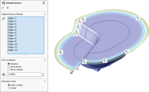
FIGURE 32.11 The Extend Surface PropertyManager
The only item here that requires explanation is the Extension Type panel. The Same Surface option means that the extended surface will simply be extrapolated in the selected direction. A planar surface is the easiest to extend because it can go on indefinitely without running into problems. A cylindrical surface can be extended only until it runs into itself. Complex lofted or swept surfaces are often difficult to extend. Extrapolating a complex surface isn't easy to do and often results in self-intersecting faces, which will cause the feature to fail.
When the Same Surface setting works, it creates a nice result because it doesn't create an edge where the extension begins; it smoothly extends the existing face.
The Linear option is more reliable than the Same Surface option because it starts tangent to the existing surface and keeps going in that direction, working much like a Ruled Surface. It doesn't rely on extending the existing surface. This option creates an edge at the starting point of the new geometry.
Using Trim Surface
![]() The Trim Surface feature was described briefly earlier in this chapter, but it warrants a more complete description here. Surfaces can be trimmed by three types of entities:
The Trim Surface feature was described briefly earlier in this chapter, but it warrants a more complete description here. Surfaces can be trimmed by three types of entities:
- Sketches
- Planes
- Other surfaces
When you use surface bodies to trim one another, you have two options: Standard or Mutual Trim. The Standard option causes one surface to act as the Trim tool and the other surface to be trimmed by the Trim tool. When you select the Mutual Trim option, both surfaces act as the Trim tool, and both surfaces are trimmed.
For an example of trimmed surfaces, open the mouse example from Chapter 31 and step through the tree. This shows a couple of types of trimmed surfaces, as well as extended surfaces and others.
Many people overlook the ability to trim a surface with a plane, which can be very handy sometimes. Planes are infinite, which means you have less to worry about when it comes to changes that affect features rebuilding correctly.
Finally, the ability to trim with 2D sketches is well known, but trimming with 3D sketches is less known. A 3D sketch tool called Spline On Surface enables you to draw a spline directly on any surface body. An option exists in the Trim Surface PropertyManager to trim a surface with this type of sketch. This is very useful in many situations if you can remember that it's available.
The trimming interface can sometimes be visually confusing. When your mouse moves over a section of the surface that will be either kept or removed, that portion of the surface will change colors. Whether it is kept or removed depends on which option is selected in the PropertyManager: Keep Selections or Remove Selections.
For example, Figure 32.12 shows a portion of the bike frame.sldprt that is provided with the download material for this chapter. The vertical and horizontal tubes are being trimmed with the C-shaped and straight-line sketches, respectively. The selected portions of the tubes are set to be kept using the Keep Selections option.

FIGURE 32.12 Trimming sections of bike frame tubing, and the Trim PropertyManager
Using Fill Surface
![]() The Fill Surface feature is referred to by the SolidWorks interface and documentation as either Fill or Filled, depending on where the reference is made. In my opinion, it is one of the most powerful tools in the surface modeler's toolbox. It is sometimes amazing what this feature can do. The Fill Surface feature is intended to create oddly shaped holes between surface bodies. You can use constraint curves to drive the shape of the fill between the existing boundaries. It can even knit a surface body together into a solid, all-in-one step. Beyond this, you can use Fill Surface directly on solid models and integrate it directly into the solid automatically (much like the Replace Face function, which is described later in this chapter). While in development, it was referred to as an N-sided patch.
The Fill Surface feature is referred to by the SolidWorks interface and documentation as either Fill or Filled, depending on where the reference is made. In my opinion, it is one of the most powerful tools in the surface modeler's toolbox. It is sometimes amazing what this feature can do. The Fill Surface feature is intended to create oddly shaped holes between surface bodies. You can use constraint curves to drive the shape of the fill between the existing boundaries. It can even knit a surface body together into a solid, all-in-one step. Beyond this, you can use Fill Surface directly on solid models and integrate it directly into the solid automatically (much like the Replace Face function, which is described later in this chapter). While in development, it was referred to as an N-sided patch.
Several rather complex examples of Fill Surface are found in the bike frame example. One of these fills is shown in Figure 32.13.

FIGURE 32.13 The Fill Surface PropertyManager and the results of applying it
The first thing you should notice about the Fill Surface is that it created an oversized, four-sided patch and trimmed it to fit into the available space.
When using the Fill Surface, you'll want to have a patch completely bounded by other surfaces, as shown in Figure 32.11. Fill Surface can work with a boundary that isn't enclosed, but it works better with a closed boundary.
You can set boundary conditions as Contact, Tangent, or Curvature. Contact simply means that the faces touch at an edge. Tangent means that the slopes of the faces on either side of the edge match at all points along the edge. Curvature means curvature continuous (or C2), where the Fill Surface matches not only tangency, but also the curvature of the face on the other side of the boundary edge. This results in a smoother transition than a transition that's simply tangent.
When you select the Optimize Surface option, SolidWorks tries to fit the four-sided patch into the boundary. Notice that on this part, even though the Optimize Surface option is selected, it's clearly being ignored because the boundary is a six-sided gap and cannot be patched smoothly with a four-sided patch. It isn't necessarily an improvement to optimize a fill surface, even when it works.
Constraint curves can influence the shape of the fill surface. An example of this is shown in Figure 32.14. This screen shot is from the mouse example, controlling the shape of the thumb indentation. The construction splines shown on the faces of the part were created by the Intersection Curve tool and enabled the spline used for the constraint curve to be made tangent to the surface.

FIGURE 32.14 The Fill Surface feature with constraint curves
Using MidSurface
![]() The MidSurface feature is intended to be used in conjunction with analysis tools to create plate elements for thin-walled structures, or midplanes for flow scenarios. It works on parallel or offset faces, creating a surface midway between the faces. If the faces have opposing draft (symmetrical, such that a wall is wider at the bottom than at the top), then the MidSurface feature won't work. It works on linear walls and cylindrical walls, but not on elliptical or spline-based shapes. The PropertyManager for the MidSurface is shown in Figure 32.15.
The MidSurface feature is intended to be used in conjunction with analysis tools to create plate elements for thin-walled structures, or midplanes for flow scenarios. It works on parallel or offset faces, creating a surface midway between the faces. If the faces have opposing draft (symmetrical, such that a wall is wider at the bottom than at the top), then the MidSurface feature won't work. It works on linear walls and cylindrical walls, but not on elliptical or spline-based shapes. The PropertyManager for the MidSurface is shown in Figure 32.15.

FIGURE 32.15 The MidSurface PropertyManager
The percentage of distance between face pairs can be adjusted from the default 50 percent, and if possible, resulting faces can be knit into a single body.
Using Replace Face
![]() The Replace Face feature doesn't create new surface geometry, but it does integrate existing surface geometry into the solid. It replaces selected faces of a solid or surface body with a selected surface body. Replace Face is one of the few tools that can add and remove material with a single feature.
The Replace Face feature doesn't create new surface geometry, but it does integrate existing surface geometry into the solid. It replaces selected faces of a solid or surface body with a selected surface body. Replace Face is one of the few tools that can add and remove material with a single feature.
If you were to manually perform the functions that are done by Replace Face, you would start by deleting several faces of the solid, then extending faces, and then trimming surface bodies, and finish by knitting all the trimmed and extended faces back into a single solid body.
This is a very powerful and useful tool, although it's sometimes difficult to tell in which situations it will work. Figure 32.16 shows a part after a Replace Face feature has been performed. The surface used to replace the flat face of the solid has been turned transparent. The first selection box is for the original face or faces, and the second selection box is for the surface body with the new faces. The tool tips for each of the boxes are Target Faces For Replacement and Replacement Surface(s), which seem a little ambiguous. I like to think of them as Old (top) and New (bottom).
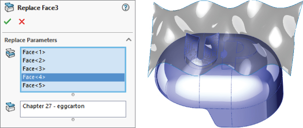
FIGURE 32.16 Using Replace Face
Using Ruled Surface
![]() Ruled surfaces are discussed in general in the section “Understanding Surfacing Terminology.” Here, I discuss the topic in more detail, specifically with regard to the SolidWorks interface for creating ruled surfaces.
Ruled surfaces are discussed in general in the section “Understanding Surfacing Terminology.” Here, I discuss the topic in more detail, specifically with regard to the SolidWorks interface for creating ruled surfaces.
The Ruled Surface feature in SolidWorks is one of those features that you may never miss until you see it in action. It's extremely useful for constructing faces with draft, extending faces tangent to a direction, making Radiate Surface types, building molds, and many other applications. It can also be frustratingly unreliable.
A ruled surface requires a model (surface or solid) edge from which to start. You cannot create a ruled surface from a sketch or curve. The icon will not even become active until you have solid or surface geometry in the graphics window.
Figure 32.17 shows the PropertyManager interface for the Ruled Surface.

FIGURE 32.17 The Ruled Surface PropertyManager interface
The Ruled Surface feature works from the edge of a solid or surface body. The feature has five basic types of operations that it can perform:
- Tangent To Surface
- Normal To Surface
- Tapered To Vector
- Perpendicular To Vector
- Sweep
The Tangent To Surface setting creates a surface that is tangent to the surface of the selected edge. The Alternate Face option would be available if the base shape had been a solid, with a face filling the big elliptical hole. This would make the ruled surface tangent to the bottom face instead of the side.
With the Normal To Surface setting, it tilts up 5 degrees from the horizontal because the surface is lofted with a 5-degree draft angle at the big end, making a ruled surface that's normal.
The Tapered To Vector setting needs a plane or axis selection to establish a direction, and then the ruled surface is created from that reference at the angle that you set. With a combination of the Alternate Side button and the arrow-direction toggle button next to the plane selection, you can adjust the cone created by this setting. The interface to make the changes isn't exactly clear unless you use this function often, but it does work.
The Perpendicular To Vector setting is a better option than the Normal To Surface setting when the surface has been created with some sort of built-in draft angle. This is also the setting that looks most like the Radiate Surface feature, although it works much better than Radiate Surface.
The Sweep setting makes a face that's perpendicular to the surface created by Perpendicular To Vector. It's as if a straight line were swept around the edge. This is actually a great way to offset an edge or 3D sketch: using the edge of the surface as the offset of the original.
Using Intersect
![]() The Intersect feature is not strictly surface-based. Its solids functions are covered in Chapter 31. Its primary purpose is to take several entities such as solid and surface bodies, faces, and planes, and create new solid bodies from combinations of those. One of the best usages of this feature is finding fill levels for liquid in a container. For example, Figure 32.18 shows a watering can with a solid block of water and then, after the Intersect feature has been applied, the volume of water that was inside the watering can.
The Intersect feature is not strictly surface-based. Its solids functions are covered in Chapter 31. Its primary purpose is to take several entities such as solid and surface bodies, faces, and planes, and create new solid bodies from combinations of those. One of the best usages of this feature is finding fill levels for liquid in a container. For example, Figure 32.18 shows a watering can with a solid block of water and then, after the Intersect feature has been applied, the volume of water that was inside the watering can.

FIGURE 32.18 Using Intersect to fill a watering bucket with liquid
If you would try to do this same example and keep the watering can intact, that would be more challenging. It might require different settings such as Invert Selection or the preview options available at the top of the region list, unless you use the Create Internal Regions option. The Intersect feature is not an easy-to-use function, mainly because the results can be tough to visualize, or select, and there are a lot of ways to use and visualize the results. The ability to turn on or off the pieces that will be kept or removed is helpful, but selecting body parts that are inside two volumes is just plain hard to do. You might want to make a copy of the watering can body and use that to be consumed in the feature, or you could do a Boolean subtract and delete the body of water that winds up outside the watering can. I recommend that you take some time to play with the sample files if you think you may have use for this particular feature.
Other nice usages for this feature include creating molds and breaking a single solid into manufacturable bodies.
Here are some of the unique capabilities of the Intersect tool:
- Can add and subtract material in the same feature
- Can later completely change methods without needing to delete and re-create the feature
- Can add surfaces and planes to combine feature options
- Can make bodies from the empty spaces that are fully enclosed
- Can consume bodies (or not) as you wish
- Can output multiple solid bodies (imagine combining several bodies when some of them are not touching at all)
Tutorial: Working with Surfaces
The best way to learn about surfaces is to experiment. I recommend that you closely follow the tutorial steps once, and then when you understand the concepts involved, you can go back and experiment.
Using Cut With Surface
![]() Follow these steps to gain some experience with the Cut With Surface feature:
Follow these steps to gain some experience with the Cut With Surface feature:
- Create a new part, and draw a rectangle on the Top plane, centered on the origin, about 4 inches by 6 inches, with the 4-inch dimension in the vertical direction.
- Extrude the rectangle mid-plane, by 2 inches.
- From the Surface toolbar, select Lofted Surface, and select one 4-inch edge as a loft profile. Then select a second 4-inch edge diagonal from the first one. This is shown in Figure 32.19.

FIGURE 32.19 Lofting a surface from the edges of a solid
- Expand the Start/End Constraints panel and set both ends to use the Direction Vector setting, selecting the plane in the middle of the long direction in each case. In the part shown, the Right plane is used. Click OK to accept the feature. This is shown in Figure 32.19.
- From the menus, choose Insert ➢ Cut ➢ With Surface. Select the surface from the flyout FeatureManager, and toggle the arrow direction so that the top is cut off. (The arrow points to the side that's cut off.)
Using Offset Surface
Follow these steps to gain some experience with the Offset Surface command:
- Open the part called
Offset Tutorial.sldprtfrom the download materials. - Right-click a curved face of the part and click Select Tangency in the menu.
- With the faces still selected, from the Surfaces toolbar, click Offset Surface and set the surface to offset to the outside of the part by .060 inches. You can tell when the surface is offsetting to the outside when the transparent preview appears. If you don't see the transparent preview, toggle the Flip Offset Direction arrow button. Click OK to accept the feature when you're satisfied.
- Look in the Surface Bodies folder at the top of the FeatureManager tree, expand the folder, use the Display pane (F8) to change the transparency, as shown in Figure 32.20. This is done so you can see the part underneath the surface, without mistaking the surface for the actual part.

FIGURE 32.20 Using the Display pane to change transparency
- Select Sketch2 and select Extruded Boss/Base from the Features toolbar. Don't mistake the extruded surface for an extruded solid. Set the end condition to Up To Body, activate the Body Selection box, and select the Offset Surface body from the Surface Bodies folder. The result is shown in Figure 32.21.
- To invert the lettering so it sits below the surface rather than above the surface, you can make a few simple changes. Edit the Offset Surface feature and flip the direction of the offset so the surface is inside the solid rather than outside the solid. You can't see it unless the solid is either transparent or in Wireframe mode.
- Delete the extrude that you created to extrude the text. There's no way to change an extrude into a cut in this context.
- Re-create the extrude as an extruded cut. Use the From settings at the top of the PropertyManager window. The settings and results are shown in Figure 32.22. Another way to accomplish this is to use the Move Face tool, select the faces of the letters, and move them .120 of an inch into the solid.
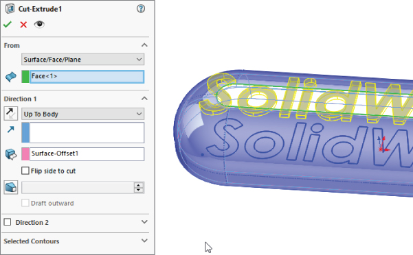
FIGURE 32.22 An extruded cut
Using Fill Surface Blend
Sometimes, fillets don't meet your needs. Blends, such as those shown in the bike frame example, are smoother and can blend just about anything. However, the technique is not exactly straightforward. Follow these steps to gain familiarity with this technique:
- Open the part called
Blend.SLDPRTfrom the download data for Chapter 32. Box select all the features from the DeleteFace1 to the Shell and suppress them. - On the Top plane, draw a square 2 inches on a side and centered on the origin.
- Use the Split Entities tool found on the Sketch toolbar, or choose Tools ➢ Sketch Tools ➢ Split Entities from the menus. Divide each line of the rectangle into three pieces, with the two outer pieces of each line being .6 inches (use an Equal sketch relation). The sketch should be fully defined when you're finished. This arrangement is shown in Figure 32.23. This is done because the edges of the tubes need to be broken into sections.

FIGURE 32.23 Using split entities to split lines
With the lines split, now use the Split Line tool at Insert ➢ Curves ➢ Split Line to split the faces of all tubes.
- Use Delete Face to delete the ends of the four tubes. Set the option to Delete, not the default option of Delete And Patch. This converts the solid into a surface body.
- Use the sketch with the split entities to trim out the center section of the tubes, keeping the outer section and leaving four surface bodies. This divides each tube end into four segments where they have been trimmed, as shown in Figure 32.24.

FIGURE 32.24 Split ends after trimming
- Initiate the Lofted Surface feature and select the nearest edge segments from adjacent tubes. If the loft preview twists, use the light-blue handles to straighten it out or deselect and reselect one of the edges in approximately the same location as the other edge was selected. Expand the End Conditions panel and set each edge to use the Curvature setting. You may adjust the End Tangent Length option if you want, but keep in mind that this may make the part asymmetrical.
As a note, you may choose to use the Boundary Surface feature in the place of the Loft feature. For this function, the two are similar enough.
- Create lofted surfaces all the way around the part, linking all the tubes. Figure 32.25 shows the part with three of the lofts already completed and the last one in progress.

FIGURE 32.25 Adding lofted surfaces
- Start a Planar Surface feature and select the open ends of each tube where the faces were deleted in step 4.
- Start a Knit Surface feature and Shift+select all the bodies in the Surface Bodies folder (select the first body in the list and Shift+select the last body). When you click OK to accept the feature, notice that the number of surface bodies changes to one. Selecting bodies in this way is much faster for large numbers of bodies than selecting them one at a time from the graphics window.
- Right-click any of the open edges and choose Select Open Loop. Initiate the Fill Surface. Change the Edge setting option to Tangent and make sure that the Apply To All Edges option is selected. Select the Merge Result option, but leave the Try To Form Solid option unselected. The model at this point is shown in Figure 32.26, along with the PropertyManager settings that are used.

FIGURE 32.26 Creating a Fill Surface patch
This is the type of situation for which the Fill Surface is really meant. In fact, this technique was created specifically to take advantage of the Fill Surface capabilities.
- Click OK to accept the feature.
- Start another Fill Surface feature, turning the part over to use the same selection on the back and the same settings as the first fill. However, on this one, also use the Try To Form Solid option. Click OK when the selections and settings are complete.
- For the last feature, apply a Shell feature, selecting the flat ends of the tubes and shelling to .100 inches. The final state of the model is shown in Figure 32.27.

FIGURE 32.27 The finished model
The Bottom Line
Surface functions have a wide range of uses other than for complex shape parts, but thinking about your models in terms of surface features requires a slightly different approach. Becoming comfortable with the terminology, and the similarities and differences between solids and surfaces, is the first step toward embracing surfacing tools for everyday work.
You can think of surfaces as being reference geometry—stand-alone faces that you can use to complete various tasks.
- Master It Sketch a rectangle and extrude it as a surface. Then close one of the open sides with a planar surface and knit together the two surface bodies. Next, use the Thicken tool to thicken the surface into a hollow box.
Notice the change from the count in the Surface Bodies folder to the Solid Bodies folder. Save the part.
- Master It Open the part saved in the previous exercise, and use Save As to make a copy of it with a new name.
Delete the Thicken feature.
Use a Fill feature to close the open side in the box, and use the options in the Fill feature to knit the part into a single surface body and make it solid.
- Master It Open the part used in the previous exercise and use Save As to save it with a new name.
Use the Move Copy Bodies command to make a copy of the solid body, and move the copy to one side so it does not touch the original.
Use Delete Face to delete one face of the new body. Notice that the solid body changes to a surface body.
Use a Loft surface to again close up the missing face, use Knit to knit it into a single surface body, and use Thicken to make it a solid body again.
Finally, use the solid Loft feature to loft between the two faces of the solid bodies that are closest to one another, and merge the result so there is a single solid body in the part.