
Chapter 6
Getting More from Your Sketches
Previous chapters described the basic tools for sketching. This chapter takes you to the next level and teaches you about more advanced sketch tools, as well as how to edit and manipulate sketches, and how to work with sketch text, sketch pictures, and sketch colors. By the end of this chapter (with a little practice to reinforce the tools and techniques), you should feel like you have mastered the topic of SolidWorks sketching and can handle almost any problem that is thrown at you.
Editing Sketch Relations
Delete is not an editing option. In time, you'll find that this is good advice, even if you don't agree with it now. There are times to delete instead of editing, but you should delete only when it is necessary. Especially while learning, you should strive to at least know how to repair instead of delete in every situation. In my own work, I sometimes go to extreme lengths to avoid deleting sketch entities, in part to stay in practice, but also because when you delete sketch entities, dependent features may lose their references or go dangling. Because of this, even when you can use the Delete command instead of making edits, it is still good practice to edit instead. Deleting relations is not as critical as deleting sketch entities, unless the relations are referenced by equations or design tables.
Using Display/Delete Relations
![]() Display/Delete Relations is the primary tool for dealing with sketch relations. It is particularly useful for sorting relations by the various categories shown in Figure 6.1. The capability to show sketch relations in the graphics window is nice; sorting them in a list according to their state makes this feature even more useful. To show the sketch relation symbols on the screen beside the sketch entities, use the View ➢ Sketch Relations menu selection.
Display/Delete Relations is the primary tool for dealing with sketch relations. It is particularly useful for sorting relations by the various categories shown in Figure 6.1. The capability to show sketch relations in the graphics window is nice; sorting them in a list according to their state makes this feature even more useful. To show the sketch relation symbols on the screen beside the sketch entities, use the View ➢ Sketch Relations menu selection.

FIGURE 6.1 The Display/Delete Relations PropertyManager
The sketch relations in the Display/Delete Relations dialog box can be divided into the following categories:
- All In This Sketch: This shows all the relations in the active sketch.
- Dangling: This shows only the dangling relations. Dangling relations appear in a brownish-green or olive color and represent relations that have lost one of the entities that drives the relation. You can repair dangling relations by selecting the entity with the dangling relation and then dragging the red dot onto the entity to which it should have the relation.
- Overdefining/Not Solved: Overdefined relations are any set of conflicting instructions that are given to a sketch entity; they appear in red or yellow. If a line has conflicting relations, but it can still meet the requirements, it turns yellow. If the sketch relations cannot be solved, it turns red.
- When an overdefined situation exists as shown in Figure 6.2, all the relations and dimensions in a sketch often become overdefined. This can look like a daunting task to repair, especially when the entire problem is caused by a single relation. Do not automatically delete everything. Instead, try deleting or suppressing the last dimension or relation that was added, or any single relation that looks suspect. You can suppress a dimension by setting it to Driven in the right mouse button (RMB) menu, and you can suppress relations in the Display/Delete Relations PropertyManager.

FIGURE 6.2 An overdefined sketch
- When an overdefined situation exists as shown in Figure 6.2, all the relations and dimensions in a sketch often become overdefined. This can look like a daunting task to repair, especially when the entire problem is caused by a single relation. Do not automatically delete everything. Instead, try deleting or suppressing the last dimension or relation that was added, or any single relation that looks suspect. You can suppress a dimension by setting it to Driven in the right mouse button (RMB) menu, and you can suppress relations in the Display/Delete Relations PropertyManager.
- External: External relations connect with an entity outside the active sketch. This includes the part origin or any model edges. The term external relations can also signify any relations outside of the part.
- Defined In Context: Any relation between features in one part in an assembly and another part is considered an in-context relation.
- Locked (Broken): External relations (outside the part) may be locked or broken to increase speed and to lock out parametric changes. There is no advantage to breaking relations rather than locking them. Both are ignored, but locked relations can be unlocked; broken relations can only be deleted.
- Selected Entities: Sketch relations are shown only for the selected sketch entities.
In-context design, also called top-down, as well as locked and broken relations are covered in detail in Chapter 20, “Modeling in Context.”
A setting in Tool ➢ Options controls the display of errors. You can choose Tools ➢ Options ➢ FeatureManager to find an option called Display Warnings. There you can choose Always, Never, and All But Top Level. When a sketch contains sketch relations with errors, they display as warning signs on the sketch and will propagate to the top level of a part or assembly if you have selected the Always option.
Using Replace Entity
![]() The Replace Entity tool enables you to swap out a particular sketch entity with all of the associated references further down the tree reconnected. When you extrude a rectangle into a solid, for example, all of the faces and edges that are created are given specific names so that the software can internally keep track of what references what. If you were to change one of the lines of the rectangle to an arc by making the line a construction line and drawing a new arc, then rebuilding the solid, any faces or edges that were built from the original line would now be different; and if any features like a fillet referenced the original edge, they would fail. Using Replace Entity makes sure that everything updates properly. It is easy to do, but in order for it to work, you have to actually use it. Here is a step-by-step procedure to help you see how the tool works:
The Replace Entity tool enables you to swap out a particular sketch entity with all of the associated references further down the tree reconnected. When you extrude a rectangle into a solid, for example, all of the faces and edges that are created are given specific names so that the software can internally keep track of what references what. If you were to change one of the lines of the rectangle to an arc by making the line a construction line and drawing a new arc, then rebuilding the solid, any faces or edges that were built from the original line would now be different; and if any features like a fillet referenced the original edge, they would fail. Using Replace Entity makes sure that everything updates properly. It is easy to do, but in order for it to work, you have to actually use it. Here is a step-by-step procedure to help you see how the tool works:
- Open a new part.
- Sketch a rectangle on any standard plane, making sure one corner references the origin.
- Extrude the rectangle to some depth.
- Apply a Fillet feature to an edge parallel to one of the sketch lines, as shown in Figure 6.3.

FIGURE 6.3 Filleting an edge
- Expand the Boss-Extrude1 feature in the FeatureManager so you can see the Sketch1 underneath it.
- Right-click Sketch1 and select Edit Sketch.
- Sketch a three-point arc across the line that is parallel to the filleted edge, as shown in Figure 6.4. Notice the new arc is displayed as a thinner line than the lines of the rectangle.
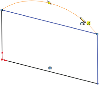
FIGURE 6.4 Sketching the arc
 Manually convert the line under the arc to construction.
- Use the Confirmation Corner to close the sketch. Notice that the Fillet feature fails.
- Right-click Sketch1 and select Edit Sketch.
- Convert the construction line back to a regular line.
- In the menu, select Tools ➢ Sketch Tools ➢ Replace Entity.
- Make sure the line is in the top box and the arc is in the bottom box, with the settings as shown in Figure 6.5.
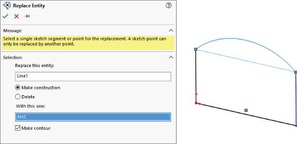
FIGURE 6.5 Replacing a line with an arc
- Exit the Replace Entity command and exit the sketch. Notice that the Fillet feature now rebuilds properly.
Using SketchXpert
The SketchXpert, shown in Figure 6.6, can help you to diagnose and repair complex sketch-relation problems. The Diagnose button at the top creates several possible solutions that you can toggle through using the forward and backward arrow buttons in the Results panel. The Manual Repair button displays all the relations with errors in a window where you can delete them manually.
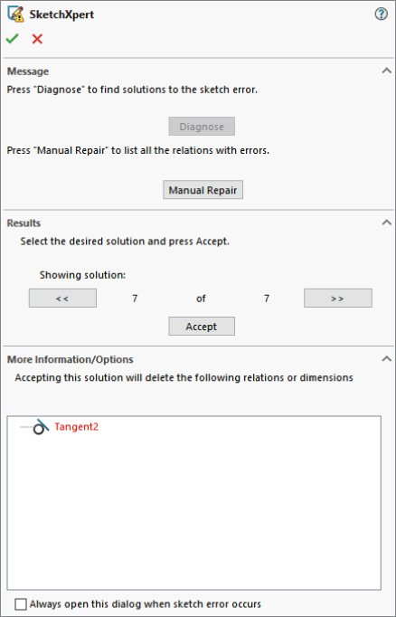
FIGURE 6.6 The SketchXpert dialog box
By selecting the option at the very bottom of the dialog box—always open this dialog when a sketch error occurs—you can make the SketchXpert appear whenever a sketch error occurs. To display the SketchXpert manually instead of automatically, you can access it by right-clicking in any sketch or clicking in the Over Defined warning on the right end of the status bar.
Getting More from Dimensions
Dimensions have some workflow enhancements that might not be obvious if you don't know about them. One of my favorites is dimensioning from centerlines.
Dimensioning from Centerlines
In Figure 6.7, I have dimensioned from a centerline. Notice that the cursor changes and displays an R, which indicates that the next dimension will be radial and will be made with respect to the centerline. This means that if I select the center of one of the holes, it will be dimensioned from the centerline.When placing the dimension that originally went to the centerline, if I had placed it on the other side of the centerline, SolidWorks would have given me a diameter dimension on the cursor displayed with a D (for diameter). Selecting the circle itself cancels the function because that implies a diameter, not a distance from something.
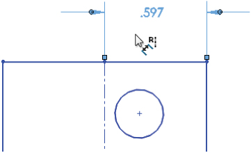
FIGURE 6.7 Dimensioning from centerlines
If you want to get out of the Radial or Diameter Dimension mode, press Esc on the keyboard to revert to normal dimensioning. This feature works like automatic baseline dimensioning.
Sketching with Numeric Input
To use the numeric input, first enable it with Tools ➢ Options ➢ Sketch ➢ Enable On Screen Numeric Input On Entity Creation.
With the Create Dimension Only When Value Is Entered setting turned on, when you sketch a rectangle, for example, SolidWorks automatically dimensions the length and height of the rectangle. The catch here is that you must use click+click sketching. Click-and-drag cannot be used with this technique. After you click the first corner of the rectangle, SolidWorks will put up a numeric entry field; and if you enter a number, it will automatically put dimensions on the rectangle and prompt you to edit one of them. You can then key in another dimension for the other side of the rectangle.
Working with Sketch Entities
SolidWorks offers several different tools to help you move sketch entities around in a sketch. In SolidWorks, I recommend keeping the sketch as simple as you can and creating patterns using feature patterns rather than sketch patterns. This section discusses the main tools for moving and copying sketch entities.
Moving, Rotating, Copying, and Scaling Entities
 Move Entities Tool The Move Entities tool enables you to move selected sketch entities by either selecting From and To points or by entering XY coordinates for the move. When the Keep Relations Option is unselected, the Move tool automatically detaches sketch segments whose endpoints are merged, as shown in Figure 6.8. If Keep Relations is selected, SolidWorks moves the entities and tries to maintain the sketch relations and merged points. All the tools have a pushpin icon in the interface. You can use the tool multiple times in succession when the pushpin icon is pushed in; tools with the pushpin are deactivated after one use if the pushpin icon is not pushed in.
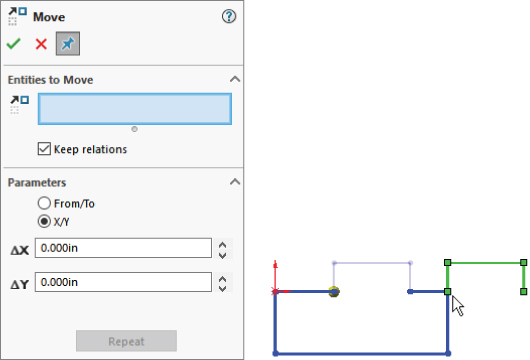
FIGURE 6.8 Using the Move tool
- Rotate Entities Tool The Rotate Entities tool rotates selected entities in a sketch in the same way that Move Entities works. You can drag the angle or enter it manually. The green checkmark icon is on the RMB, as shown in the cursor display in Figure 6.9.
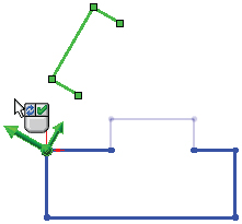
FIGURE 6.9 Using the Rotate tool
- Keep Relations Option The Keep Relations option does not actually keep any relations—it deletes the Horizontal and Vertical relations in the sketch, as shown on the left in Figure 6.8—but it does keep the merged endpoints, as shown on the right in Figure 6.8. This can be useful, especially considering how many sketch relations it would take to make a sketch move like this naturally.
- Copy Entities Tool The Copy Entities tool works exactly like the Move Entities tool, except that it copies instead of moving. The Copy Entities tool enables you to copy selected sketch entities by either selecting From and To points or by entering XY coordinates to place the copy. SolidWorks copies the entities and tries to maintain the sketch relations and merged points.
- Scale Entities Tool Scale Entities is one of those functions probably best left alone. This is because the results are erratic and unpredictable, particularly if there are dimensions on the sketch. This tool works on a selection of entities, particularly on an isolated selection that is not connected to other entities in the sketch. The PropertyManager for the Scale Entities tool is shown in Figure 6.10.
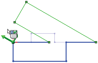
FIGURE 6.10 The Scale PropertyManager
Modifying a Sketch
![]() The Modify Sketch tool has been available in SolidWorks for a long time, but it has been superseded by some of the newer tools, such as Move Entities. However, it still has some unique functionality that is not covered by any other sketch tool. Modify Sketch works on the entire sketch rather than on selections within the sketch. It works best if there are no external relations between sketch entities and anything outside the sketch. It can also work on a sketch without the sketch being active. While most feature and tool interfaces have been moved to the PropertyManager, Modify Sketch still uses a dialog box (shown in Figure 6.11) that floats in the graphics window.
The Modify Sketch tool has been available in SolidWorks for a long time, but it has been superseded by some of the newer tools, such as Move Entities. However, it still has some unique functionality that is not covered by any other sketch tool. Modify Sketch works on the entire sketch rather than on selections within the sketch. It works best if there are no external relations between sketch entities and anything outside the sketch. It can also work on a sketch without the sketch being active. While most feature and tool interfaces have been moved to the PropertyManager, Modify Sketch still uses a dialog box (shown in Figure 6.11) that floats in the graphics window.
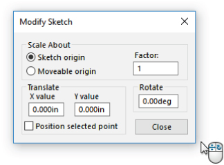
FIGURE 6.11 The Modify Sketch dialog box
The Modify Sketch dialog box enables you to perform the following functions:
- Scale About: The Scaling function in the Modify Sketch tool enables you to scale about either the part origin or the movable origin. The movable origin is shown with a black origin symbol with knobs on the ends of the axes and at the intersection. The movable origin can be moved and even snapped to entities that are internal or external to the sketch.
- Translate: The Translate function of the Modify Sketch tool enables you to click and drag to move the entire sketch or to select a point and move it to a specific set of coordinates that you enter. If the sketch is dragged onto an external entity and picks up an automatic relation, then a message may appear saying that you can now use Modify Sketch only for rotating the sketch because there is an external relation.
- Rotate: The Rotate function of the Modify Sketch tool enables you to position the movable origin to act as the center of rotation. You can rotate either by entering a rotation angle or by dragging with the right mouse button to rotate, as indicated by the cursor.
When you place the cursor over the knobs on the movable origin, the cursor symbols change to indicate the functionality of the RMB. These cursors are shown in action in Figure 6.12. The cursors enable rotation, mirroring about X, Y, or both simultaneously.
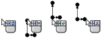
FIGURE 6.12 The Modify Sketch tool's cursors
Copying and Pasting Sketch Entities
Probably the simplest way to copy sketch entities in a sketch is to select the entities and use Ctrl+C, Ctrl+V, or one of the many other methods available for this purpose (such as the RMB button menu, the Edit menu, or Ctrl+dragging). Copying with box dragging, lasso, Ctrl+A, or contour selection are all useful methods.
In addition to copying selected entities within an active sketch, you can also select a sketch from the FeatureManager and then copy and paste it to a selected plane or planar face (if you are not in a sketch to begin with). This creates a new sketch feature in the FeatureManager that is not related to the original, although it does maintain internal dimensions and relations. (External relations are not copied with the sketch.) This is particularly useful when setting up certain types of lofts that use several profiles that can be created from a single copied profile. Copying and pasting is a fast and effective method of putting sketches on planes.
A copied sketch is similar to a derived sketch (addressed later in this chapter), except that with a copied sketch, there is no link or internal relations; and with the derived sketch, the new and old sketches remain identical through changes to the original sketch.
Dragging Entities
If a selected set of sketch entities has no external relations, you can select it as a group and move it without distorting or resizing the sketch. For the best results with this technique, avoid dragging endpoints; drag an actual line.
Creating a Derived Sketch
A derived sketch is a parametrically linked copy. The original parent and derived sketches do not need to have any geometrical relation to one another, but when the parent sketch is changed, the dependent derived copy is updated to stay in sync.
To create a derived sketch, you can select a plane or planar face, Ctrl+select the sketch you want to copy, and then choose Insert ➢ Derived Sketch.
Once you create a derived sketch, you cannot change its shape or size; it works like a block of a fixed shape driven by the parent. However, you can change the position and orientation of the derived sketch. Figure 6.13 shows a derived sketch and its parent. Modify Sketch is a great tool to use for manipulating derived sketches that are not related to things outside the sketch, especially for mirroring or rotating.
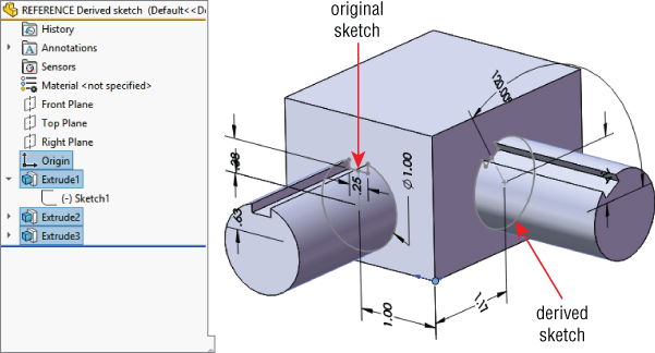
FIGURE 6.13 A derived sketch and its parent
Using Sketch Pictures
Sketch pictures are images that are placed in a sketch. You can resize and rotate the images, give them a transparent background, trace over them, and suppress them. They display as children of the sketch in the FeatureManager. You can use these image types as sketch pictures: BMP, GIF, JPEG, TIFF, PNG, PSD, and WMF.
To bring a picture into a sketch, the sketch must first be active. Click Sketch Picture on the Sketch toolbar (it is not there by default, so you may need to drag it onto the Sketch toolbar from the Tools ➢ Customize ➢ Commands dialog box). You can also access this command by choosing Tools ➢ Sketch Tools ➢ Sketch Picture from the menu. You cannot use sketch pictures in assembly sketches, but you can use them in a part sketch in an assembly.
To change the size of a sketch picture, you can double-click it and drag one of the handles around the outside of the image. Refer to Figure 6.14 for the Sketch Picture PropertyManager. When the picture comes into the sketch, it is usually too big, having been sized at a ratio of 1 pixel to 1 mm. To size a picture accurately, you should include a ruler or an object of a known size in the image. If you cannot do this, the next best thing is to guess the size. Draw a line in your sketch and dimension it to approximately the size of something that is recognizable in the image, and then move the image by clicking and dragging it to lay the dimensioned sketch entity as close over the object in the image as possible.
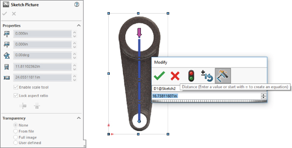
FIGURE 6.14 The Sketch Picture PropertyManager with a scaling tool enabled
SolidWorks has also included scaling functionality. When you insert the picture, you will see a pink dot and a pink arrow connected by a blue line. Position the dot first and then the arrow; SolidWorks will provide a Modify box to allow you to specify how long the blue line should be.
You can rotate and mirror images using the Sketch Picture PropertyManager. Images are opaque, and you cannot see the model through them, but at the same time, you also cannot see the images through the model. They are like flat pieces of paper that are pasted to the model or hanging in space.
You can add transparency to images, either by selecting a color or by using the built-in transparency in the image file (alpha channels are available only in certain types of image files). When you select a color to be transparent, you also need to increase both the Matching Tolerance and the Transparency sliders, which are by default set to their minimum values.
Using Three Views
When you're building a model from images, it is often helpful to have three or more images from orthogonal views, similar to re-creating a part from a 2D drawing. If you have a left view and a right view, it may be a good idea to put them on planes that are slightly separated so the images are not exactly on top of one another, which makes them both hard to see. Putting them on slightly offset planes means that one will be clearly visible from one direction and the other visible from the other direction.
Each sketch picture must be in a separate sketch. Figure 6.15 demonstrates the use of multiple sketch pictures to trace the outline of a vehicle, with the partially complete model shown with the images.
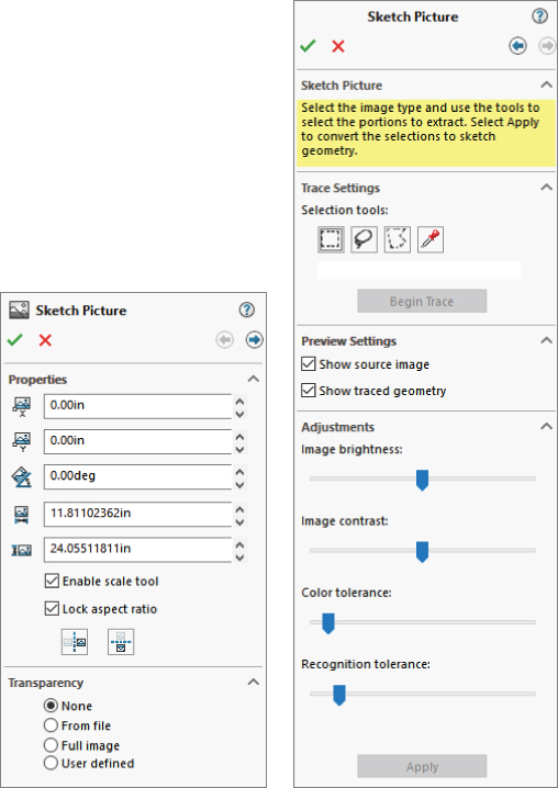
FIGURE 6.15 Using multiple sketch pictures
Additionally, you can put multiple sketch pictures inside a single sketch. Both images will show up in the FeatureManager, and both can be displayed at the same time, although you may have difficulty if you want to put them on top of one another.
Compensating for Perspective
When taking digital photographs to be used as sketch pictures in SolidWorks, you have to consider how perspective affects the image. Perspective can make it difficult to size items in the foreground or background. If you are taking the pictures that will be used as sketch pictures, you can minimize the effects of perspective by standing farther away from the object and using zoom on the camera if possible.
Estimating Sharp Edges
When you are sketching an object, you usually draw theoretically sharp corners of the model. Real parts usually have rounded corners, so you may have to use your imagination to project where the 3D surfaces would intersect at an edge minus the fillets.
Reverse-modeling a part from images is not an exact science. It is better than not being able to put pictures into the sketch, but there is nothing about it that can be considered precise. Often, putting a ruler or size gauge in the image somewhere is useful.
Using Auto Trace
Auto Trace is an add-in that you can select by choosing the Tools ➢ Add-ins menu. Auto Trace is intended to trace between areas of contrast in sketch pictures, creating sketch entities. Activating the Auto Trace add-in activates a set of arrows at the top of the Sketch Picture PropertyManager. There is nothing to identify the functionality with the Auto Trace name.
Auto Trace works best with solid blocks of black and white in the sketch pictures. To achieve this, you may need to use image-processing software and reduce your picture to a two-color (black and white) bitmap, TIF, or PNG image. Even if this preprocessing gives perfect results, don't expect much from Auto Trace.
Using Stick Fonts
SolidWorks makes available the OLFSimpleSansOC Regular font for those times when you need a stick font in your sketch to drive CNC machinery.
Using Sketch Text
Sketch text uses TrueType fonts to create text inside a SolidWorks sketch. This means that any TrueType font you have can be converted to text in solid geometry; this includes Wingdings and symbol fonts. Keep in mind that some characters in certain fonts do not convert cleanly into SolidWorks sketches. Sketch text must still follow the rules for sketching and creating features such as closed contours. You cannot mix open and closed contours.
You can make sketch text follow a sketch curve. To space the text evenly along the curve, you can control character width and spacing, as well as overall size, by specifying points or actual dimensions. Sketch text can also be justified right, left, centered, and evenly, as well as reversed, rotated, and flipped upside down. Figure 6.16 shows the Sketch Text PropertyManager and some examples of sketch text options.

FIGURE 6.16 Examples of sketch text
The icons in the Sketch Text PropertyManager are self-explanatory, other than the Rotated Text option; Rotated Text rotates individual letters (as shown in the Dimension the Placement Point text in Figure 6.16) and not the whole string of text.
You can use the Sketch Text tool multiple times in a single sketch to make pieces of text with different properties. Each string of text has a placement point located at the lower left of the text. This point can be given sketch relations or dimensions to locate the text.
If the text overlaps in places, as shown in Figure 6.16, you can correct this in a couple of ways. First, you can extrude it with the Merge option unselected, so each letter is created as a separate solid body and then manually merged later. You can also explode sketch text so it becomes simply lines and arcs in a sketch, which you can edit the same as any other sketch (not recommended). You can also adjust the Width Factor and Spacing settings. Or, you can extrude some letters in a separate feature so that if the features overlap, at least the characters don't overlap in a single sketch.
You can link the text to a custom property. This means that sketch text can be changed with configurations. (Configurations are covered in a later chapter.) The text used to extrude a feature can come from custom properties, which can be driven by a design table or directly through the Sketch Text PropertyManager.
Using Colors and Line Styles with Sketches
Custom colors and line styles are usually associated with drawings, not sketches; in fact, they are most valuable when used for drawings. In sketches, this functionality is little known or used, but it's still of value in certain situations.
Working in Color Display Mode
![]() The Color Display Mode button is found on the Line Format toolbar. In drawings, you can use the Color Display Mode button to switch sketch entities on the drawing between displaying the assigned line or layer color and displaying the sketch status color. It has exactly the same effect in part and assembly sketches.
The Color Display Mode button is found on the Line Format toolbar. In drawings, you can use the Color Display Mode button to switch sketch entities on the drawing between displaying the assigned line or layer color and displaying the sketch status color. It has exactly the same effect in part and assembly sketches.
When you select the button, the sketch state colors are used. When the button is not selected, any custom colors that you have applied to the sketch entities appear. If the button is not selected and you have not applied colors to the entities, the default sketch state colors are used.
You can use sketch colors for emphasis, to make selected sketch entities stand out, or to make sketches with various functions immediately distinguishable. Color Display mode has an effect only on an active sketch. Once a sketch is closed, it returns to the gray default color for inactive sketch entities.
Assigning Line Color
![]() Line color enables you to assign color to entities in an active sketch. The Color Display Mode tool determines whether the assigned color or the default sketch status colors are used. Chapter 28, “Using Layers, Line Fonts, and Color,” has more information on this functionality, especially related to drawings.
Line color enables you to assign color to entities in an active sketch. The Color Display Mode tool determines whether the assigned color or the default sketch status colors are used. Chapter 28, “Using Layers, Line Fonts, and Color,” has more information on this functionality, especially related to drawings.
Using the Edit Sketch or Curve Color Tool
![]() The Edit Sketch Or Curve Color tool can be found on the View toolbar. You can use the Edit Sketch Or Curve Color tool to assign color to an inactive sketch or to a sketch block to replace the default gray color. The color that you assign to sketches in this way displays only when the sketch is inactive. The sketches also follow the toggle state of the Color Display Mode button. For example, if the Color Display Mode button is selected, then inactive sketches display as gray. When the Color Display Mode button is not selected, then inactive sketches display in any color that you have assigned by using the Edit Color tool.
The Edit Sketch Or Curve Color tool can be found on the View toolbar. You can use the Edit Sketch Or Curve Color tool to assign color to an inactive sketch or to a sketch block to replace the default gray color. The color that you assign to sketches in this way displays only when the sketch is inactive. The sketches also follow the toggle state of the Color Display Mode button. For example, if the Color Display Mode button is selected, then inactive sketches display as gray. When the Color Display Mode button is not selected, then inactive sketches display in any color that you have assigned by using the Edit Color tool.
When you use this tool to color a sketch block, the block displays the color inside the active sketch. You cannot use the Line Color tool mentioned earlier to assign color to a block.
Assigning Line Thickness and Line Style
![]() The Line Thickness and Line Style tools function independently from the Color Display Mode button, but they are still used only when the sketch is active. As soon as a sketch that contains entities with edited thickness and style is closed, the display goes back to the normal line weight and font.
The Line Thickness and Line Style tools function independently from the Color Display Mode button, but they are still used only when the sketch is active. As soon as a sketch that contains entities with edited thickness and style is closed, the display goes back to the normal line weight and font.
To assign a thickness or a style, you can select the sketch entities to be changed, click the button, and then select the thickness or style. Although a single sketch entity may have only a single thickness or style, you can use multiple thicknesses or styles within a single sketch. Figure 6.17 shows a sketch with the thickness and style edited.
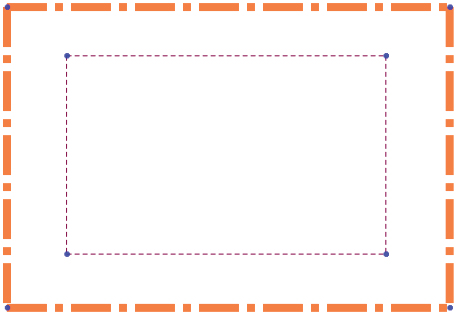
FIGURE 6.17 A sketch with edited line thickness and line style
Line thickness and line styles are covered in more detail in the discussion of drawings in Chapter 30, “Creating Assembly Drawings.”
Using Other Sketch Tools
SolidWorks has lots of functionality that overlaps between multiple topics. The following tools could appear in other sections of the book, but I include them here because they will help you work with and control 2D sketches in SolidWorks.
Working with RapidSketch
![]() RapidSketch is meant to help you easily change sketch planes. As you move a sketch cursor over flat faces of a model, the faces highlight to indicate that you can start a new sketch there. Each new sketch appears in the FeatureManager.
RapidSketch is meant to help you easily change sketch planes. As you move a sketch cursor over flat faces of a model, the faces highlight to indicate that you can start a new sketch there. Each new sketch appears in the FeatureManager.
The workflow with this tool is that you start in one sketch with RapidSketch activated. Activate a sketch tool, move the cursor over a plane or face, and a dark plane will appear to indicate you can start sketching on that plane. To move to another plane, the sketch tool must still be active, but not be in-progress on an entity (nothing attached to the cursor). This option makes SolidWorks sketching work more like Solid Edge, where it's easier to change to a new sketch.
Adding Sensors
![]() You can add sensors in the SolidWorks FeatureManager for parts and assemblies by right-clicking the Sensors folder and selecting Add Sensor. You can find the Sensors folder at the top of the FeatureManager. If you cannot find the Sensors folder, make it visible by choosing Tools ➢ Options ➢ FeatureManager, and make sure the Sensor folder is set to Show.
You can add sensors in the SolidWorks FeatureManager for parts and assemblies by right-clicking the Sensors folder and selecting Add Sensor. You can find the Sensors folder at the top of the FeatureManager. If you cannot find the Sensors folder, make it visible by choosing Tools ➢ Options ➢ FeatureManager, and make sure the Sensor folder is set to Show.
You are not limited to using sensors only when working with sketches; you can use them outside of sketches in parts and assemblies to warn you when various types of parameters meet various types of criteria.
Figure 6.18 shows the Sensor PropertyManager. You can create sensors for measurements, simulation data, or mass properties. I included sensors in this chapter due to the measurement options, which enable you to select a dimension and set a range of values or criteria for which you want to be notified. The dimension can be a driving (black) sketch dimension, a driven (gray) dimension on a sketch, or even a driven dimension placed directly on solid geometry.

FIGURE 6.18 The Sensor PropertyManager
Figure 6.18 shows what happens when a sensor finds a condition that you asked it to notify you about.
In addition to turning sensor alarms on or off, you can suppress sensors when they are no longer needed or to improve performance.
Sensors are a great way to keep an eye on particular values, such as wall thickness or clearance between parts. You can use a sensor to monitor any value you want to monitor but don't drive directly.
Using Metadata for Sketches
Metadata in SolidWorks is nongeometrical text information attached to geometrical data. Metadata is particularly helpful as keywords in searches, in Product Data Management (PDM) applications, or as custom properties in drawing and tables. If you don't use metadata within your CAD documents, it can be easy to forget that it is there at all.
You can use the following items as metadata in SolidWorks files:
- Sketch and feature names
- Sketch and feature comments (access comments via the RMB menu)
- Custom properties
- Design Binder documents
- Tags for features (located in the lower-right corner of the status bar)
Metadata searches can be particularly useful in large assemblies or parts with long lists of features that you need to find or search through. You can conduct searches for metadata through the FeatureManager Filter at the top of the FeatureManager. The Advanced Search function in assemblies can also search metadata sources. SolidWorks Explorer is a good first-level data management solution that can search, display, and edit metadata and previews. Windows Explorer can also search properties and tags.
Creating Construction Geometry
In SolidWorks, the only construction geometry that can be created directly is the construction line. All other sketch entities can be converted to construction geometry by selecting the Construction Geometry option within the sketch entity's PropertyManager or by using the Construction Geometry toggle toolbar button.
SolidWorks terminology is inconsistent, because it sometimes refers to construction lines as centerlines. The two are really the same thing. Centerlines are used for revolved sketches and mirroring, but there is no difference between a centerline and a construction line in SolidWorks.
Construction geometry is useful for many different types of situations. I use it frequently for reference sketch data. You can make sketch relations to construction geometry, to create symmetry, and you can use it for layout sketches or many other purposes.
Sketching in 3D
![]() The 3D sketch is an important tool for creating weldments (and many other features) in SolidWorks. 3D sketches can be challenging, but they are certainly manageable if you know what to expect from them.
The 3D sketch is an important tool for creating weldments (and many other features) in SolidWorks. 3D sketches can be challenging, but they are certainly manageable if you know what to expect from them.
Earlier chapters discussed the tools that are available for 2D sketches; next, I cover techniques for 3D sketching.
Navigating in Space
To start a 3D sketch, activate the 3D Sketch icon on the flyout under the 2D sketch icon; or, in the menus, go to Insert ➢ 3D Sketch. When drawing a line in a 3D sketch, the cursor and origin initially look like those shown in Figure 6.18. The large red origin is called the space handle, with the red legs indicating the active sketching plane. Any sketch entities that you draw lie on this plane. The cursor also indicates the plane to which the active sketching plane is parallel. In the XY graphic shown in Figure 6.19, the sketch is not required to be on the XY plane, just on an imaginary plane parallel to it.

FIGURE 6.19 The space handle and the 3D sketch cursor
Pressing the Tab key causes the active sketching plane to toggle between XY, YZ, and ZX. The active sketching plane indication does not create any sketch relations; it just lets you know the orientation of the sketch entities that are being placed. If you want to create a skew line that is not parallel to any standard plane, you can do this by sketching to available endpoints, vertices, origins, and so on. If there are no entities to snap to, you will need to accept the planar placement, turn off the sketch tool, rotate the view, and move one end of the sketch entity.
The biggest challenge with 3D sketches is visualization. It can be tough to see if a line is coming out of the screen or is just a short line in another plane. An excellent tool to help you visualize what is happening in a 3D sketch is the Four Viewport view. This divides the screen into four quadrants, displaying the front, top, and right views in addition to the trimetric or isometric view. You can sketch or edit in any of the viewports, and the sketch will update live in all the viewports simultaneously. This arrangement is shown in Figure 6.20. You can easily access the divided viewport screen by using buttons on the Standard Views toolbar. You can also manually split the screen by using the splitter bars at the lower-left and upper-right ends of the scroll bar areas around the graphics window. These window elements are also described in Chapter 2, “Navigating the SolidWorks Interface.”

FIGURE 6.20 The Four Viewport view
When unconstrained entities in a 3D sketch are moved, they move in the plane of the screen. This can lead to unexpected results when viewing something at an angle, moving it, and then rotating the view, which shows that it has shot off into deep interplanetary space. This is another reason to use the Four Viewport view, which enables you to see what is going on from all points of view at once.
Exploring Sketch Relations in 3D Sketches
Sketch relations in 3D sketches are not exactly the same as in 2D sketches. Relations are not projected into a plane in a 3D sketch the way they are in 2D. For example, an entity in a 2D sketch can be made coincident to an entity that is out of plane. This is because, to make the relation, the out-of-plane entity is projected into the sketch plane, and the relation is made to the projection. In a 3D sketch, coincident means coincident, with no projection.
Several relations are available in 3D sketches that are not found in 2D sketches, such as AlongX, AlongY, AlongZ, and OnSurface.
As a general caution, keep in mind that solving sketches in 3D is more difficult than it is in 2D. You will see more situations where sketch relations fail or they flip in the wrong direction. Angle dimensions in particular are notorious in 3D sketches for flipping direction if they change and go across the 180-degree mark. When possible, it is advisable to work with fully defined sketches and to be careful (and conservative) with sketch relations.
Using Planes in Space
![]() It is possible to create planes directly in 3D sketches. These planes work like regular planes initially. Having planes in the sketch also enables planar sketch entities such as arcs and circles in 3D sketches. Sketches can be created on these planes, and the sketch will move with the plane, but the plane will also move with the sketch. Planes within 3D sketches can be confusing if you expect them to work like 2D sketches and planes.
It is possible to create planes directly in 3D sketches. These planes work like regular planes initially. Having planes in the sketch also enables planar sketch entities such as arcs and circles in 3D sketches. Sketches can be created on these planes, and the sketch will move with the plane, but the plane will also move with the sketch. Planes within 3D sketches can be confusing if you expect them to work like 2D sketches and planes.
Figure 6.21 shows the PropertyManager interface for creating 3D planes.

FIGURE 6.21 The 3D Planes PropertyManager
The confusing part is this: Say you create a vertical line on a plane in a 3D sketch. You can then angle the line, and the plane will rotate with it. There is no way to rotate the plane on its own unless you have some sketch geometry on the plane and cause that to rotate.
![]() To open a sketch on a plane in a 3D sketch, double-click on the sketch or use the 3D Sketch on Plane tool. The plane is activated when it displays a grid. You can double-click an empty space to return to regular 3D Sketch mode. The main thing you give up with abandoning 3D sketch planes is the simplification of certain sketch entities such as arcs and relations.
To open a sketch on a plane in a 3D sketch, double-click on the sketch or use the 3D Sketch on Plane tool. The plane is activated when it displays a grid. You can double-click an empty space to return to regular 3D Sketch mode. The main thing you give up with abandoning 3D sketch planes is the simplification of certain sketch entities such as arcs and relations.
The advantage of using planes within a 3D sketch is that you abandon the parent/child concept that you would otherwise embrace if you used a series of 2D sketches and 2D planes. In my opinion, 3D sketches are an incredibly useful tool; however, the 3D planes concept is not very well developed. I'm not ready to say it's dangerous, but it certainly is not fully thought out.
Using Planar Path Segments
Some path segments that are allowed in 3D sketches can be used only if they are sketched on a plane. These entities include circles and arcs and can include splines, although splines are not required to be on a plane. I've already mentioned that to sketch on a 3D plane (a plane created within the 3D sketch), you can simply double-click the plane.
To sketch on a standard plane or reference geometry plane, you can double-click the plane or Ctrl+click the border of the plane with the Sketch Entity icon active. The space handle moves, indicating that newly created sketch entities will lie in the selected plane.
Defining Dimensions
Dimensions in 2D sketches can represent the distance between two points, or they can represent the horizontal or vertical distance between objects. In 3D sketches, dimensions between points are always the straight-line distance. If you want to get a dimension that is horizontal or vertical, you should create the dimension between a plane and a point (the dimension is always measured normal to the plane) or between a line and a point (the dimension is always measured perpendicular to the line). For this reason, reference sketch geometry is often used freely in 3D sketches, in part to support dimensioning.
Using 3D Sketch Summary
Three-dimensional sketches are extremely powerful for many different applications. The problem is that they are also limited in some of their capabilities, and they do not work exactly like 2D sketches. You will benefit from knowing how to use 3D sketches at some point, even if it isn't every day.
Tutorial: Editing and Copying
This tutorial guides you through some common sketch-relation editing scenarios and using some of the Copy, Move, and Derive tools. Follow these steps to learn about editing and copying sketches:
- Open the part named
Chapter6 Tutorial1.sldprtfrom the download materials for Chapter 6. This part has several error flags on sketches. In cases where there are many errors, it is best to roll the part back and go through the errors one by one. - Right-click the name of the file at the top of the FeatureManager, click the Tree Display option, and select Show Flat Tree (Ctrl+T). This is a function that allows you to show the features in a straight history list, without features consuming sketches.
- Drag the Rollback bar from just after the last fillet feature to just after Sketch3. Figure 6.22 shows before and after views for the rollback.
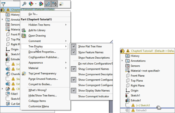
FIGURE 6.22 Rolling the part back to Extrude3
 Edit Sketch3, and then Right-click in the white space and select Display/Delete Relations. Notice that all the relations conflict, but only one is unsolvable: the Equal Radius relation. This appears to be a mistake because the two arcs cannot be equal.
- Delete the Equal Radius relation. Select the relation in red and click the Delete button in the PropertyManager. (You can also press the Delete key on the keyboard.) The sketch is still not repaired.
- Click the green checkmark icon to close the Display/Delete Relations PropertyManager.
- Right-click the graphics window and select SketchXpert (toward the bottom); then click Diagnose.
- Using the double arrows in the Results panel, toggle through the available solutions. All the solutions except one remove sketch relations and leave the sketch underdefined. Accept the one solution that removes the dimension. This is shown in Figure 6.23. The sketch no longer shows errors in the graphics window, but it still does in the FeatureManager.

FIGURE 6.23 Using the SketchXpert to resolve an overdefined sketch
- Close the sketch. Notice that the error flag does not disappear until the sketch has been repaired and closed.
- Use the Rollback bar to roll forward to after Extrude2 and Sketch2. Figure 6.24 shows the tool-tip message that appears if you place the cursor over the sketch with the error. This message tells you that there is a dangling relation—a relation that has lost one of the entities.
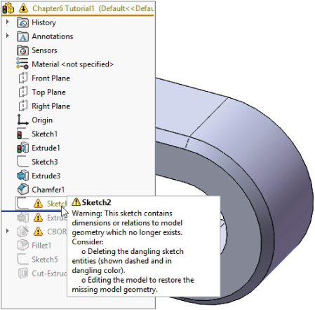
FIGURE 6.24 A tool tip provides a description of the error.
- Edit the sketch (see Figure 6.25). If you show the Sketch Relation icons again, the errors will be easier to identify. When you use Display/Delete Relations (Tools ➢ Relations ➢ Display/Delete Relations), the first two Coincident relations appear to be dangling. Clicking the relation in the Relations panel of the Display/Delete Relations PropertyManager shows that one point was coincident to a line and the other point was coincident to a point.
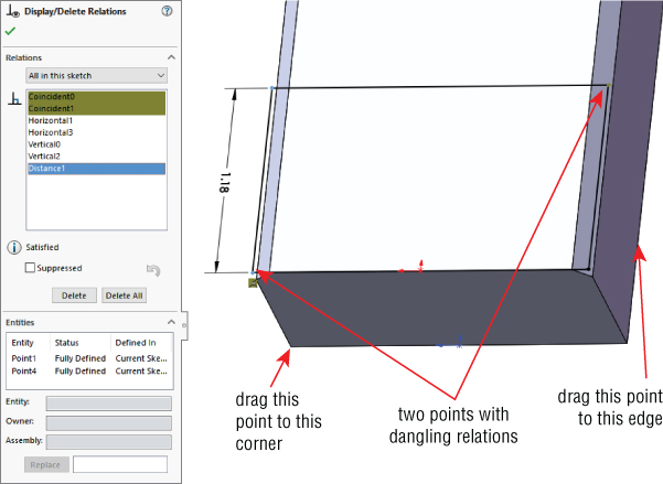
FIGURE 6.25 Fixing dangling errors
- Click the name of the dangling entity in the Entities panel of the PropertyManager; then click the vertex indicated in Figure 6.25 in the Replace box at the bottom. When you have fixed the errors, exit the sketch and confirm that the flag is no longer on Sketch2.
An easier way to repair the dangling relation is to click the dangling sketch point once. It will turn red. Next, drag the red handle onto an entity to which you want to reattach the relation.
- Exit the sketch.
- Drag the Rollback bar to just before CutExtrude1 and expand the CBore feature. (This should be already flattened, but the Flat Tree view does not apply consistently to all types of features, which is a bug.) Edit 3DSketch1. This sketch is overdefined.
- Double-click any of the relation icons; the Display/Delete Relations PropertyManager will appear. Notice that one of the sketch relations is a Fixed relation. Delete the Fixed relation and exit the sketch.
- Right-click anywhere in the FeatureManager and select Roll To End.
- Click CutExtrude1 in the FeatureManager so you can see it in the graphics window, and then click a blank space to deselect the feature.
- Ensure Instant 3D is disabled, then Ctrl+drag any face of the Cut feature, and drop it onto another flat face. The Ctrl+drag function copies the feature and the sketch, but the external dimensions and relations become detached.
- Click Dangle in response to the prompt. This means that you have to reattach some dangling dimensions rather than re-create them. Edit the newly created sketch, which now has an error on it.
- Two of the dimensions that went to external edges now have the olive dangling color. Select one of the dimensions; a red handle will appear. Drag the red handle and attach it to a model edge. Do this for both dimensions. The dimensions will update to reflect their new locations. Exit the sketch and verify that the error flag has disappeared.
- Select Sketch5. Ctrl+select a flat face on the model other than the one that Sketch5 is on. In the menu, choose Insert ➢ Derived Sketch. You are now in a sketch editing the derived sketch.
- Dimension the center of the large circle to two perpendicular edges of the model. Move the sketch over the solid geometry if necessary.
- Drag the smaller circle and observe that it swivels around the larger circle. Create an angle dimension between the construction line between the circle centers and one of the model edges. Notice that the sketch is now fully defined.
- Exit the sketch and look at the name of the derived sketch in the FeatureManager. The term Derived appears after the name, and the sketch appears as fully defined.
- Right-click the sketch and select Underive Sketch. Notice that the sketch is now underdefined. The Underive command removes the associative link between the two sketches.
- Close the file.
Tutorial: Controlling Pictures, Text, Colors, and Styles
This tutorial guides you through some of the miscellaneous functions in sketches. It also shows you what they are used for and how they are used. Follow these steps to learn how to control these items:
- Open a new part using a template with inches as units. Open a sketch on the front plane and draw a construction line starting from the origin 12 inches down (negative Y), away from the origin.
- Insert a sketch picture in this sketch. Use
Sketch Picture 1.tiffrom the download material for Chapter 6. Use Tools ➢ Sketch Tools ➢ Sketch Picture. - Resize and reposition the image so the endpoints of the construction line are near the centers of the holes on the ends of the part. To move the image, just double-click it first and then drag it. To resize it, drag the corners—or use the Scale tool in the Sketch Picture PropertyManager if you prefer.
- In the Transparency panel of the Sketch Picture PropertyManager, select the User Defined option, select the Eyedropper tool, and then click in the white background of the image. Make sure that the color field next to the Eyedropper tool changes to white.
- Slide the Transparency and Matching Tolerance sliders all the way to the right, or type 1.00 in the number boxes.
- Close the sketch and rename it Sketch Image Front View.
- Insert the image
Sketch Picture 2.tif, also from the website download, in a sketch on the right plane, and resize it to fit with the first image. Center it symmetrically about the origin. Also, set the transparency to the same setting as the first image. - Open a new sketch, also on the front plane, and draw two circles to match the features on the ends. Extrude them using a Mid Plane extrusion to match the image in the other direction (about 2.5 inches), as shown in Figure 6.26.
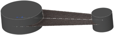
FIGURE 6.26 Using sketch pictures
- Open another new sketch on the front plane and draw the tangent lines to form the web in the middle of the part. Use the automatic relations to draw the lines tangent to the two cylinders. It is easiest if you use the front view for this. Close the sketch to make a solid extrusion. Extrude this part 0.5 inches Mid Plane.
- Open a new sketch on the face of the large flat web that you created in the previous step, and offset the arc edge of the larger circular boss by 2.10 inches.
- Change the arc to a construction arc and drag its endpoints to approximately the position shown in Figure 6.27. The endpoints of the arc will be blue after you drag them. Give them a Horizontal relation and then dimension them.
To create the 2.10 dimension as shown, select the arc and circle with the Dimension cursor while pressing down the Shift key.
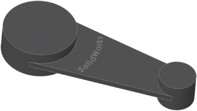
FIGURE 6.27 Creating an offset arc
- Choose File ➢ Properties. Make sure the Custom tab is active, and type Sketch Text in the first open box of the Property Name column. Make sure the Type is set to Text, and in the Value field, type SolidWorks. Click OK when you are finished.
- Choose Tools ➢ Sketch Entities ➢ Text to initiate the creation of sketch text.
- Select the construction arc to go into the Curves window.
 Below the Text window, click the Link To Property button. Select Sketch Text from the Property Name drop-down list, then click OK. Select the Full Justify option and click the green checkmark icon to accept it.
- Deselect the Use Document Font option, click the Font button, and then set the Units to 0.50 inches. Click the Bold button to make the text thicker. Click OK to exit the dialog box. Click the green checkmark icon to exit the sketch text, and then exit the sketch.
- Extrude the text to a depth of .050 inches with 3 degrees of draft. The part at this point resembles Figure 6.28.

FIGURE 6.28 Creating extruded text
- Select the flat face on the other side of the part from where you just extruded the text, and open a sketch.
- Select the face and click the Offset button to make a set of sketch entities offset to the inside of the face by .50 inches. Remember that you may have to reverse the offset to get it to work properly.
- Open the Line Format toolbar (right-click any toolbar other than the CommandManager and select Line Format).
- Select all the sketch lines, and change their color using the Line Color tool. Change the line thickness and the line style using the appropriate tools. The sketch should look something like Figure 6.29.
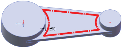
FIGURE 6.29 Using line thickness and line style
- When you click the Color Display Mode tool, the colors will return to regular sketch colors. When you exit the sketch, the line weight and style will also return to normal.
Tutorial: Using Metadata
If you integrate the use of metadata into your company's modeling process, your SolidWorks models can be a resource for much more than just geometrical data. In this tutorial, discover the hidden treasure of extra information stored as metadata in this model.
- Open the part from the downloaded material called
Chapter 6 – Dials Cover.sldprt. - Check the Custom Properties in this file by choosing File ➢ Properties. Notice the Thickness and Process properties in particular.
- Add a custom property called Material, type Text, and value ABS. The Custom Property interface is located at File ➢ Properties.
- Check the comments in this part. Notice that a Comments folder exists near the top of the FeatureManager. Inside it is a list of the features for which I have written comments.
- Add a comment by right-clicking the VarFillet3 feature, selecting the Comment flyout arrow, and clicking the Add Comment option. Click the Date/Time Stamp button and add a comment that includes the word Blend.
- Check the tags for the part by clicking the small yellow tag in the lower-right corner of the status bar, click any feature, and then double-click in the Tags interface box.
- Add a tag by selecting the Cut-Extrude1 feature and adding the tag pilar.
- Right-click any item in the FeatureManager and select Go To from the options.
- Type 37 in the box and click the Find Next button. The FeatureManager should highlight a feature near the bottom of the tree named Fillet37.
- Click Fillet37 in the Feature Manager and select the Zoom To Selection tool. Zoom To Selection is a magnifying glass with an equal sign in it. The display zooms and pans to a fillet on one end of the part.
- Right-click a face of Fillet37 on the model and select Go To Feature (In Tree), which selects the FeatureManager if necessary and scrolls to show Fillet37. This sequence of tools shows the importance and interdependence of feature names and the actual geometry.
- Type the word Thickness in the filter at the top of the FeatureManager. Figure 6.30 shows the result. Notice how quickly the results appear. Notice also that the metadata item that caused the feature to show in the list can be shown in a tool tip by hovering the mouse over the feature.

FIGURE 6.30 Using the FeatureManager filter to search for metadata
- Click the X at the right end of the filter to restore the FeatureManager to its original state, and type the word Pilar instead. Now filter for Thermoform.
Tutorial: Sketching Calculator
Sketches can be used as geometrical calculators. Parametrics can be extremely powerful when you can define relationships between geometry. In this tutorial, you will set up a sketch to calculate the complex size and location relationships between the rings of a child's stacking toy.
- Open a new part document with inch units.
- Draw a triangle with a rounded top with the base centered on the origin, as shown in Figure 6.31. Do not use dimensions; use sketch relations and construction geometry to enable it to change symmetrically.
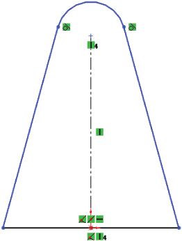
FIGURE 6.31 Build a triangle with a rounded top without dimensions.
- Draw three circles to the right of the pyramid. The bottom circle should be tangent to the bottom and the angled side of the pyramid. The middle and top circles should be tangent to the lower circle and the angled side of the pyramid, respectively. Figure 6.32 shows this process partially completed.

FIGURE 6.32 Sketching stacking rings
- Put a diameter dimension on each circle. In the PropertyManager for each dimension, rename the dimension for
ring1dia@Sketch1, ring2dia, and so on. This is shown in Figure 6.33.
FIGURE 6.33 Naming dimensions
- Place a dimension from the center of the bottom circle to the construction line, and place the dimension on the far side of the construction line from the circle. This creates a diameter dimension.
- Place a dimension for the middle circle in the same way as the bottom circle, but this time, make the dimension value about 75 percent of the first diameter.
- Complete the sketch as shown in Figure 6.34, with all the dimensions and sketch relations.
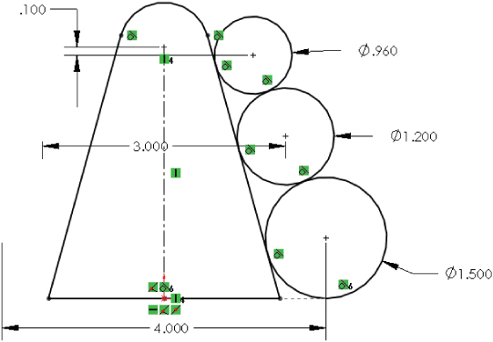
FIGURE 6.34 The finished sketch
- Make changes to the sketch to see which changes it allows and which it does not. Double-click dimensions and use the wheel in the middle of the Modify dialog box to apply changes smoothly. Try changing each dimension.
The Bottom Line
- Edit sketch relations. Effectively using sketch relations is a fundamental skill that you need to have to be successful with SolidWorks. You will use them constantly to make sure your models behave predictably to change.
- Master It Open one of the sample parts from this chapter, show the flat tree, and edit each sketch. Make sure you understand what each sketch relation is doing.
- Reverse engineer a simple part using digital images. Take pictures from at least two sides of a simple object you can model using simple extrude features, trying to make the photos look like drawing views. Use the images as sketch pictures, align the edges on the photo with the X and Y of the sketch, and sketch over them.
- Master It Insert the photos into sketches and model with the image as a reference.
- Create a wireframe representation of a chair from 3D sketches. 3D sketches are frequently used in many types of design. Getting some practice drawing lines in 3D space will help you gain command of these tools.
- Master It Start by creating the centerlines of the square members of a simple wooden chair.