
Chapter 18
Using Libraries, Assembly Features, and Hole Wizard
Libraries help you make more efficient use of data that you will reuse frequently. Some features can be made to be very flexible so you can apply them in a wide range of situations. Some libraries, such as the Hole Wizard, are premade and can be combined with automation to create tools like Smart Components, which are library parts that can use library features and resize as necessary.
Shared libraries in multiuser environments require additional setup, including Windows permissions settings and SolidWorks File Location settings.
Using Library Features
Library features are intended to be parametrically flexible to fit into many types of geometry, but they can also be of a fixed size and shape. In this chapter, you will use the information you have learned in previous chapters about designing for change and design intent, and you will learn how to create, use, and store library features.
Library features reside in the Design Library, which is located in the Task pane to the right of the graphics window.
One very useful aspect of library features is that they can be driven by configurations and design tables. After the feature is in the part, the configurations are still available, so you can change the config of an applied library feature at any time.
You can also link a library feature to an external file. This enables you to change a feature or a set of features in several parts at once if they are all externally linked to the file.
Getting Started with Library Features
Library features are simple to use and only slightly less simple to set up. For that reason, I will discuss using them first, so you know what kind of behavior you are trying to create when you go to make your own features.
To use a library feature, drag and drop it from the Design Library onto the appropriate geometry. You will then be prompted to select references in the new part that match the base geometry to which the library feature is attached. You can be fairly creative with references, but one of the goals when creating the feature is to make it work with as few references as possible. Fewer references make the feature easy, fast, and reliable to use.
SolidWorks software installs with several sample library features in the Design Library. The following demonstration uses some of these standard library features. Later, you can add library features from the download files to your Design Library.
Applying the Library Feature Interface
Library features work best if they go from a certain type of base geometry to a similar type of base geometry—for example, from rectangular to rectangular or from circular to circular. This is because the relations or dimensions that link the feature to the rest of the part tend to be dimensions from straight edges or concentric sketch relations. Of course, there are other ways of applying library features, but these are the most prevalent. Library features can be applied unconstrained and then constrained or moved later, but the process is cleanest when it all falls together correctly the first time.
USING THE TASK PANE
You don't have to save the part or do anything special before applying a library feature. You simply need to find the Task pane. The Task pane is the window that flies out from the right when you open SolidWorks. You may have turned it off and forgotten about it, in which case you can turn it on by choosing View ➢ Task Pane from the menu.
The Task pane automatically closes when you click outside of it unless you pin it open using the pushpin icon in the upper-right corner of the window. When you do this, any toolbars that appeared on the right side of the Task pane control tabs are moved out and positioned between the graphics window and the Task pane, which now remains open by default.
You can also detach the Task pane by dragging the bar at the top of the pane. Figure 18.1 shows the Task pane docked to the right side of the SolidWorks window.
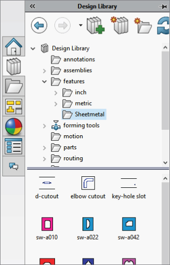
FIGURE 18.1 The Task pane docked to right side of the SolidWorks window
USING THE DESIGN LIBRARY
![]() The Design Library tab displays an image of a stack of books. It is the overall library area for all sorts of elements in SolidWorks. The part of the Design Library to be concerned with now is the Features folder. If you expand this folder, you can see that it is populated with some sample features.
The Design Library tab displays an image of a stack of books. It is the overall library area for all sorts of elements in SolidWorks. The part of the Design Library to be concerned with now is the Features folder. If you expand this folder, you can see that it is populated with some sample features.
Open a new part, and create a cylinder using any method you want (for example, extrude or revolve). Make the diameter 3 inches and the length a little more than 1 inch.
In the Expand the Features ➢ Inch subfolder and select O-Ring Grooves. The first feature in the list is called face static – gas. Drag and drop this feature onto the end flat face of the cylinder.
The next step is to select the configuration, as shown in Figure 18.2. Not all library features have multiple size configurations. The configs in this case are driven by design tables. Select configuration 330.

FIGURE 18.2 Placing the feature and selecting the configuration
When you select the configuration, the interface changes. In this case, only a sketch relation locates the feature; it is not located by dimensions. Notice that in the References panel, there is an Edge entry with a question mark, which becomes a check mark after you select the edge. This means that the library feature needs a circular edge to locate it. A small window appears, displaying the library feature. You need to select an edge that has the same relation to the library feature as the highlighted edge. Pick the circular edge of the part on the end of the cylinder where you want to place the library feature.
Next, create a new part from a rectangle 1.5 inches by 2 inches and extrude it to about 2 inches in depth.
In the Design Library, browse to Features, then Inch, and then the Fluid Power Ports folder, and drag the SAE J1926-1 feature onto the end of the extruded rectangle. Select the 38-24 size from the configurations list. A window appears, prompting you for reference selections, as shown in Figure 18.3.

FIGURE 18.3 Placing a library feature with dimensions
After the locating edges have been identified, the Locating Dimensions box becomes active and you can change the values of the dimensions to locate the feature. Further, in the Size Dimensions pane at the bottom of the PropertyManager, selecting the Override dimension values option enables you to change dimensions of the feature itself.
When you use a library feature with a design table, the design table is not brought into the part with the library feature. If the part already had a design table, this would cause multiple tables, which is not currently possible in SolidWorks. The configurations in the design table are brought forward, however.
If you override the feature dimensions using the Override Dimension Values option in the Size Dimensions panel of the Library Feature PropertyManager when feature configurations already exist, then a new configuration called Custom Configuration will be created in the list of feature configurations. It appears that multiple custom configurations are not allowed, so if you must make changes, you must ensure that they are right before you use the library feature in a part.
Exploring Other Design Library Functions
The Design Library has other functions besides library features. For example, you can use it as a repository for other items that you use frequently.
STORING ANNOTATIONS
You can store commonly used annotations in the Design Library. If you look at the Annotations folder with the default sample annotations, you see a combination of symbols and blocks. You can use symbols and notes in 3D models, but you can use blocks only in sketches or 2D drawings. Keep in mind that not all annotation types can be used in all places.
Annotations can be stored in the library as favorites or blocks. Many file extensions are used for different types of favorites, but they typically begin with *.sld and end with fvt, as in *.sldweldfvt. Figure 18.4 shows the default location of the Design Library and the thumbnail view of the favorites and blocks in the Annotations folder.

FIGURE 18.4 The Annotations folder in Windows Explorer
LOCATION OF THE DESIGN LIBRARY FOLDER
If you frequently work with different types of annotations, you should organize the library into subfolders to separate symbols, annotations, and blocks, and move these folders to a different location. By default, the Design Library folders are found at C:ProgramDataSolidWorksSolidWorks 2018design library. You should store them in another location, not in the SolidWorks installation directory, but in an area that you have selected to maintain SolidWorks data between releases. For example, I have a folder at D:Library that contains folders for macros, templates, library features, library parts, favorites, and so on. You can easily back up or copy these files from one computer to another, although you must quit SolidWorks before making these changes. Keeping the data off the operating system drive is also a good idea because if you ever have to reinstall the OS, you won't lose your SolidWorks library data.
After moving the library, you must point SolidWorks to the new location. To do this, choose Tools ➢ Options ➢ File Locations ➢ Design Library (or access it through the Add File Location icon in the Library pane). Delete the old location and browse to the new location. You should move other items in this list and redirect any items that you use, such as the templates and any other items you use frequently. After you have specified the settings, they should be retained when you install service pack upgrades or future versions.
STORING LIBRARY PARTS
The Design Library can also store commonly used library parts. One of the advantages of using the library for parts is that placement of the library part into the assembly, if configurations are available in a part, a window pops up, enabling you to select which configuration to place into the assembly.
Figure 18.5 shows the Configuration selection window for library parts. Note that the configurations are listed alphabetically, and you can type in the box to go to the configuration you want.
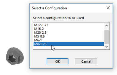
FIGURE 18.5 Selecting a Library Part Configuration
Parts inserted from the Library Parts folder can also take advantage of the Mate References functionality in the same way as the Toolbox, by allowing parts to snap into place.
USING SHEET METAL FORMING TOOLS
I only mention sheet-metal-forming tools here as a part of the library. They work much the same as other library features, but they do so within the specialized functions of sheet metal parts in SolidWorks. I discuss sheet-metal-forming tools in Chapter 35, “Creating Sheet Metal Drawings.” Forming Tools folders have special properties. If you want to use the parts in a folder as forming tools, you must right-click the folder in the Design Library and choose Forming Tool Folder. The only other library type that needs a special folder is the one for library assemblies.
USING ASSEMBLIES
You can use library assemblies in SolidWorks in the same ways that you use library parts because they are inserted into the top-level assembly as a subassembly. For subassemblies that require motion, such as universal joint subassemblies, you can set the subassembly to solve as flexible or simply dissolve the subassembly into the upper-level assembly.
ROUTING
SolidWorks Routing-Electric is a separately purchased add-in that is included with SolidWorks Office Premium. It includes piping, tubing (rigid and flexible), and wiring. Routing makes extensive use of libraries and automation, but it isn't part of the scope of this book.
USING SMART COMPONENTS
Smart Components are components that resize by automatically selecting configurations, depending on the size of the geometry onto which they are being dropped. They do this from a design table—such as the interface that you set up to enable it to automatically select part configurations based on mating part sizes. For example, a clamp with many sizes driven by configurations would select the correct config when it is dropped onto different sizes of cylinders.
Smart Components are covered more thoroughly later in this chapter.
Creating Library Features
When you save library features to the library, they use the file extension *.sldlfp (library feature part). They must contain some base geometry, which simulates the part onto which the feature will be dropped. The base geometry isn't transferred to the new part; only features that are marked with the “L” (for Library) in the FeatureManager are transferred to the new part. Figure 18.6 shows the FeatureManager of a library feature part.

FIGURE 18.6 The FeatureManager of a library feature part
Creating a Library Feature
When you are creating a library feature, the first problem you need to solve is how the feature will be located on a new part. Does it need to be placed on cylindrical parts, rectangular parts, other types of shapes, or does this matter at all? Will the feature be located by using dimensions or sketch relations, or will it be placed underdefined and later fully defined manually rather than automatically?
You may have noticed in one of the earlier examples that the sample fluid power ports had two versions of the same feature. One version is intended for the feature to be placed on the flat end of a cylinder, and the other version is intended for the feature to be placed on a rectangular face.
UNDERSTANDING LIBRARY LIMITATIONS
Library features can contain multiple features of different types. They may add and remove material, even within a single library feature. However, a few limitations exist. For example, they require a base feature, and external references are not allowed, nor are surfaces, sheet metal, weldments, or molds-related features. In addition, you cannot add a scale feature (a feature that affects the entire body) to the library, nor can you apply library features to an assembly.
CREATING A NEW LIBRARY FEATURE
For this example, I use a rectangular base. The library feature that I want to create consists of two boss extrudes, a cut extrude, and several fillets.
First, you need to create a rectangular extrusion. The size should be bigger than the feature that goes on it and representative of the face of the end part onto which this feature will typically be placed.
Next, in creating the features that you want to reuse, you must pay attention to any references outside the sketch; these include absolutely anything outside the active sketch, such as the sketch plane, references to edges, the origin, other planes, other sketches, and axes. Each reference to anything that isn't already part of the library feature must be reconnected when you place the feature on a new part. The ideal situation is obviously a single drag-and-drop, but generally speaking, at least one other step is usually needed. The initial drag-and-drop determines the starting face for the feature, and from there, you usually need to locate features, either by using relations or dimensions. A concentric relation locates the feature in a single reference selection of a circular edge (although it may also need to be rotated), and dimensions typically require one dimension in the X dimension and another one in the Y dimension.
Figure 18.7 shows the base feature and the first feature of the library feature. The only relations between the sketch of the library feature and the base feature are the sketch plane and the two dimensions.

FIGURE 18.7 Creating a library feature
You should ensure that subsequent features after the first one reference only the first feature of the library feature (which is the second feature in the part). This is not a mandatory requirement, but a helpful guideline. You can make additional references, but they should be limited to the same items that were already referenced if possible. Users who model carelessly or do not pay attention to what they are doing typically have trouble making library features that function and are easy to use. Successfully modeling library features is like planning a strategy in a game of chess.
Now you can add the second extruded feature, being careful to reference only geometry that's going to move with the library feature. Figure 18.8 shows the newly added feature. To follow along as I detail how this feature is built, open the part from the download materials under the filename Chapter 18 First Library Feature.sldlfp.

FIGURE 18.8 Adding the next feature to the library feature
Notice that a plane has been added. The plane is made to reference only geometry that is internal to the library feature; it's perpendicular to an edge at the midpoint, which simultaneously locates and orients the plane correctly to enable it to be used to mirror the Ear feature.
Also, notice that the EarSketch uses the same face reference from the base feature. This will appear in the Reference list as a single reference.
SAVING THE LIBRARY FEATURE
You can use three methods to save a library feature. You can either drag and drop it into a Design Library folder, use the Save As method, or use the Add To Library button in the Task pane. Because Save As is a little more common, I will describe it first.
The first step in saving the library feature is to select all the features in the FeatureManager that are intended to be a part of the library feature. Collapse the features first so the sketches belonging to features aren't selected. If the sketches are selected, you may get a warning message saying that no selected features can be used in the library feature. Don't worry; the sketches still will be included.
With the features selected, click File, click Save As, and in the Files of Type drop-down list, select the *.sldlfp file type. Browse to the Design Library folder and save the part. Figure 18.9 shows the FeatureManager of the finished library feature.
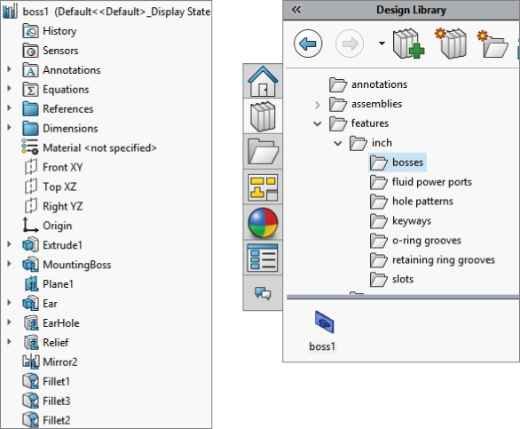
FIGURE 18.9 The finished library feature part
CHANGING THE DISPLAY OF THE LIBRARY FEATURE THUMBNAIL
During the Save As process, a new folder called Bosses was added to the Design Library, as shown in Figure 18.9. Notice the new icon for the library feature in the lower window. You may notice that some of the default library features saved in the Design Library have a bluish background, as shown in Figure 18.10. This occurs because of the SolidWorks viewport background color, which you can set by choosing Tools ➢ Options ➢ Colors. Even if you never see that color because you are using a gradient background or a scene, SolidWorks still uses the color specified by that setting as the background when saving thumbnails and previews. I always set this color to white, so document backgrounds in previews do not have the blue color.
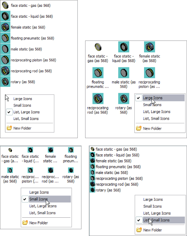
FIGURE 18.10 Display modes for the Design Library
You may want to orient and zoom the library feature before saving it so it displays clearly in the panel. I like to make the base feature a different color from the library feature itself; this technique helps me to more easily determine the geometry that will be transferred and what is just dummy material. You can also fill out the Description field for the library feature, which pops up when your cursor hovers over the icon.
The real test for a library feature comes when you actually use it. This feature is re-created perfectly on the new part, but I have noticed one problem. When the feature was placed, it was 90 degrees away from the orientation that I wanted it to be in. It seems that the only way to make the feature rotatable is to create it with parallel and perpendicular relations rather than horizontal and vertical ones, so that one of the references can act as a rotation reference. Figure 18.11 shows the completed library feature placed on a part.

FIGURE 18.11 The completed library feature placed on a part
After you place a library feature on a part, it can be edited unless you select the Link to Library Part option in the Configuration pane, in which case the feature is driven externally from the *.sldlfp file. The Link To Library Part option is available only when the feature is first placed; it isn't available when you edit an existing library feature in a part, although the Dissolve Library Feature option will break the link. This option also causes all the constituent features to become regular features in the main part. Doing this on a configured library feature destroys the configurations.
Creating a Library Feature from an Existing Part
When creating a library feature from an existing part, you use essentially the same process, but it is somewhat more difficult to achieve the correct results. It is best to remove all the features that don't either form the base feature or go into the library feature itself. This can cause many broken references, so it may be best to work from a saved copy of the original part. Most parts aren't modeled with creating a library feature in mind, and creating library features with effective references, as I mentioned earlier, is like a chess match that requires some forethought. It may be better to use a different technique, such as creating a new part with only the base feature. You can then Ctrl+drag the desired features from the existing part to the new part, set up the rest of the library feature, and save it with a *.sldlfp extension.
You can also create a library feature by dragging and dropping, although there are some limitations with this technique that seem to override the convenience. However, there is a workaround for the biggest limitation. If you select faces from features and drag them into the lower Design Library window, an Add To Library PropertyManager interface will appear that will enable you to start creating a library feature. The Add To Library PropertyManager interface is shown in Figure 18.12. You must select the features from the flyout FeatureManager. This is the source of one of the limitations. In the example, the plane cannot be selected by this method. The workaround for this is to complete the feature without the plane, right-click the icon in the Design Library window, and then select Open. With the library feature open in its own window, right-click the plane feature and select Add To Library; that individual feature is then added.

FIGURE 18.12 The RMB options for Add To Library and Remove From Library
In addition to the Add To Library option, there is also an option to Remove From Library any selected features currently part of a library feature. Ordinarily, you wouldn't see both options in the RMB menu at the same time, but I forced the issue by Ctrl+selecting both library and nonlibrary features before right-clicking.
Adding Folders to the Library
You can add folders to the library in three ways: by right-clicking in the Design Library window and selecting New Folder, by using the Windows Explorer interface, or by using the Add File Location button at the top of the Task pane. Another RMB menu option is Add Existing Folder, which enables you to add a folder from another location to the library. The folder is not moved or copied, but a shortcut is added to the Design Library and the contents appear in the lower pane.
Locating Dimensions and Internal Dimensions
When you create a library feature, SolidWorks adds two folders to the FeatureManager: the References folder and the Dimensions folder. In turn, the Dimensions folder has two subfolders: Locating Dimensions and Internal Dimensions. All these folders are shown in Figure 18.13.

FIGURE 18.13 References, Locating Dimensions, and Internal Dimensions in a library feature
The References folder shows the entities you used to reference the library feature. These are the features you are prompted to select upon placing the library feature in a new part. No additional work on your part is required with this folder.
The Dimensions folder lists all the dimensions in the library feature. Some of these dimensions are used to locate the feature to the dummy block, and some are meant to size the feature itself. When you make a library feature, I recommend that you separate the locating features from internal features by dragging the dimensions into the separate folders. The Locating Dimensions can be changed while placing the library feature, but the Internal Dimensions cannot be accessed. You may want to limit user access to some dimensions if you have standard tooling for the library feature that you are creating. Also be aware that the interface for moving the dimensions to the folders does not allow more than one dimension to be moved at a time.
Creating Assembly Cuts
Several types of design require various cuts to be made after the product is assembled. For example, plates may be stacked, clamped, and then drilled to make sure the holes line up perfectly. Cast parts may be assembled and then given a final grinding cut to remove the cast surface finish.
Some assembly cuts can also be created visually by using section views. If you do not need a physical cut to your finished assembly, you should look into using sections, which will cost you less rebuild time and cause fewer complications.
![]() To access the cut features to make an assembly cut, you can use the Assembly Features toolbar icon on the Assembly tab of the CommandManager, or you can choose Insert ➢ Assembly Feature ➢ Cut ➢ Extrude.
To access the cut features to make an assembly cut, you can use the Assembly Features toolbar icon on the Assembly tab of the CommandManager, or you can choose Insert ➢ Assembly Feature ➢ Cut ➢ Extrude.
Because removing material in the assembly is the most commonly used technique, I will discuss it first. Some additive processes exist, such as welding and techniques such as adhesives and putty fillers, and they will be discussed later in this chapter.
SolidWorks allows only certain types of features to be used as assembly cuts:
- Extruded cuts
- Revolved cuts
- Swept cuts
- Hole features
For example, you cannot use a lofted cut as an assembly feature, but you can use a lofted solid in a cavity feature (which is an in-context feature, not an assembly feature). You can also do a lofted cut of a combined solid in a single part, then split the part into multiple bodies, and then split into multiple parts (which is discussed in Chapter 33, “Employing Master Model Techniques”). SolidWorks provides many ways to do almost anything you can imagine. Your job is to determine which methods give you the most flexibility, cost you the least time, and give the most accurate results.
When you set up an assembly cut, you do it in the same way that you would set up a cut in the part environment, but with a couple of exceptions.
First, it's best to sketch on an assembly plane rather than a part face or plane that belongs to a part. This is not a requirement; it's just a best practice suggestion.
Second, you must use the Feature Scope to tell SolidWorks if you want to cut through all possible components or just selected components. Further, you can have SolidWorks automatically select parts for you. For the most stable results, it's probably best to manually select the parts that you want to cut.
Sometimes assembly cuts are created for documentation purposes rather than design purposes. For example, if you want to cut a model section and display it in an isometric view or an exploded section view, you must do that using an assembly cut, probably in conjunction with a configuration so you can also show the assembly without the section. For example, Figure 18.14 shows an isometric cutaway view created by an assembly feature, Cut Extrude.

FIGURE 18.14 Using an assembly feature to cut away a model for illustration purposes
When you place a feature in the assembly like this, the cut exists only in the context of the assembly. If you open any individual part in its own window, the part isn't cut. If you open the part in another assembly, the part isn't cut there either. The cut exists only within the assembly in which it was made.
Figure 18.15 shows the PropertyManager of the cut. The Cut-Extrude1 feature is displayed in the FeatureManager of the assembly, after the Mate folder, local patterns, and even after an assembly sketch.

FIGURE 18.15 The Feature Scope controls which parts are cut.
Using the Feature Scope
You can access the Feature Scope in the PropertyManager. In this example, all the parts were cut because the cut went through the entire assembly. In reality, some of the parts may not have needed to be cut, but in this case, it would have taken longer to find them than it did to just cut all the parts. You can partially cut the assembly in a couple of different ways. One way is to orient the feature such that you can control the depth of the cut by the sketch, and then sketch to suit your needs. Another way is to use the blind cut depth to control the depth. Finally, of course, you can use the Feature Scope to avoid cutting certain parts.
Propagating Features to Parts
One of the common mistakes SolidWorks users make is sketching in the assembly when they mean to sketch in a part in order to create a feature in the part. For example, you may not be paying attention to what you are doing, and you may forget to click the Edit Part button before starting a sketch.
In addition to that common mistake, sometimes features are simply easier to draw at the assembly level, especially if they affect multiple parts. The Feature Scope panel of the assembly feature Cut-Extrude PropertyManager contains an option called Propagate Feature To Parts. You draw the sketch in the assembly, create an assembly feature, and then select the Propagate Feature To Parts option, making sure you have the correct parts selected in the Feature Scope selection box. After you click the green checkmark icon, SolidWorks propagates the sketch and the feature to each of the selected Feature Scope parts, so the sketch and the feature reside in the FeatureManager of the individual parts.
The assembly feature cut Feature Scope is shown in Figure 18.15.
Next, you select the Propagate Feature To Parts option in the Feature Scope box to enable it. When you do this, the assembly still displays the Cut-Extrude feature at the bottom of the assembly FeatureManager, but now each part included in the Feature Scope also gets an in-context Cut-Extrude feature. If you delete the assembly-level feature, the feature will also be deleted from each of the individual parts.
Although this is a nice shortcut, it's not something you should do on a regular basis. In this particular assembly, it caused errors with about a dozen mates.
This kind of functionality also exists with the assembly fillets, chamfers, and the Hole Series functionality with Hole Wizard holes, where you specify hole locations in the assembly, and the holes show up as features in the individual parts. You can read more about the Hole Series feature later in this chapter.
Making Fillets and Chamfers in Assemblies
After parts are assembled, the corners are sometimes filed, sanded, or machined to round them. Figure 18.16 shows a stack of plates that have been filleted and chamfered in the assembly.
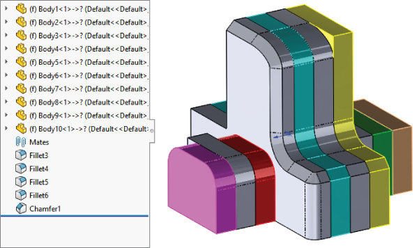
FIGURE 18.16 An example showing fillets on an assembly of stacked plates
This book sometimes uses more abstract examples so you can learn about the limitations of a feature from simplified geometry. The first thing you can learn from this particular example is that large fillets started on one part do not carry over (overflow) to other parts where you have not made a selection.
A second thing to notice is that when you are creating these fillets, they don't automatically propagate to tangent edges of other parts, as fillets in parts do. If you want to fillet a string of edges, you have to select each edge individually.
A third thing to notice is that you can use assembly fillets to add material as well as remove material. Therefore, this goes beyond the intention that assembly fillets will be used just for filing, sanding, or machining sharp edges. This is the realm of body filler putty. SolidWorks gives you capabilities here that you may not have in the real world, and what you model in the end is your own responsibility (in other words, pay attention to what you are doing).
Notice that here you also have the option to propagate the fillets to the parts.
Assembly fillets do not give you all the capabilities you have with individual part fillets. You cannot create setback, hold line, or curvature continuous fillets in this way.
Not everyone will find a use for this feature, but it does offer an alternative to the workaround options that users had to rely on in the past.
Using the Hole Wizard
The Hole Wizard uses the Toolbox database for standardized hole types and sizes. Toolbox isn't covered in this book, because it isn't part of SolidWorks Standard. Toolbox is a hardware configurator that most experienced users don't use in the intended method. Toolbox implementation, if not done correctly, can cause problems when sharing data, especially when you’re upgrading the version of your SolidWorks installation.
The Hole Wizard is mainly used in parts, but it can also be used in assemblies. It makes sense to use the Hole Wizard in the assembly to make sure that holes between parts are properly aligned and parametrically linked.
Smart Fasteners works with the Hole Wizard to automatically fill the holes created by the wizard with hardware. Hole Series is another assembly-based automated tool that links counterbored, clearance, and threaded holes in different parts in a fastened stack.
![]() The Hole Wizard enables you to place holes for many types of screws with normal, loose, or close fits. With the Hole Wizard, you can create holes as assembly features in an assembly or as features in individual parts that are built in the context of an assembly using the Series Hole functionality. This tool is called a wizard because it guides you through the process step by step. A summary of the process of using the Hole Wizard to create a hole is as follows:
The Hole Wizard enables you to place holes for many types of screws with normal, loose, or close fits. With the Hole Wizard, you can create holes as assembly features in an assembly or as features in individual parts that are built in the context of an assembly using the Series Hole functionality. This tool is called a wizard because it guides you through the process step by step. A summary of the process of using the Hole Wizard to create a hole is as follows:
- Preselecting a face to start holes before initiating the Hole Wizard command enables you to eliminate the possibility of getting a 3D sketch for the hole centers sketch. If you want holes starting from different planes, you need a 3D sketch, so select the 3D Sketch button in step 9.
- Select the type of hole—for example, counterbored, countersunk, drilled hole, tapped hole, pipe tap, or legacy. If you have favorites set up, you can select the appropriate favorite and skip to step 9.
- Set the standard to be used, such as ANSI (American National Standards Institute) inch, ANSI metric, or ISO (International Organization For Standardization).
- Select the type of screw. For example, a counterbored hole can accommodate a socket head cap screw or a hex head screw, among others.
- Select the size of the screw.
- Select the fit of the screw into the hole, such as normal, loose, or close.
- Select the end condition of the hole.
- Select the options for clearance and countersinks or edge breaks.
Alternatively, you can use or assign a favorite. A favorite is a hole with settings that you use frequently and want to save. I will discuss these later in this chapter.
You can use Custom Sizing when you need a hole with nonstandard dimensions.
- Switch to the Positions tab. If you have preselected a face, you will get a 2D sketch. If the 3D Sketch button is visible, you will also have a 2D sketch. If you click the 3D Sketch button, you will be placing sketch points in a 3D sketch. In either case, the point of this step is to place sketch points at the center of each hole you want to create. If you want holes on multiple levels, or holes on nonplanar surfaces, use the 3D sketch; otherwise, use 2D because it is simpler and faster.
- Click OK to accept the type, size, and placement of the hole. Figure 18.17 shows the Hole Wizard PropertyManager interface.
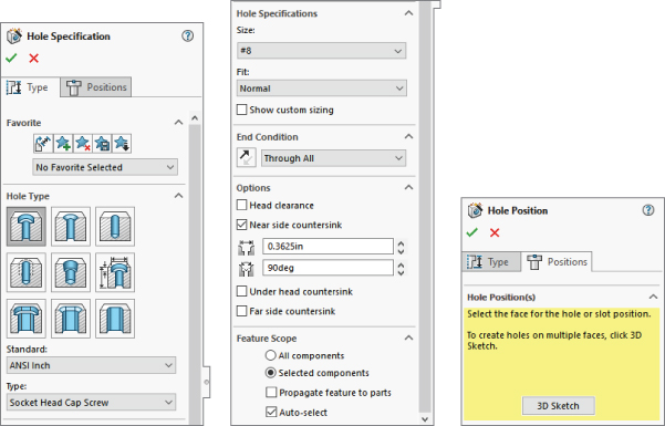
FIGURE 18.17 The Hole Wizard PropertyManager interface
Using the Hole Series
![]() The Hole Series enables you to make a series of in-context hole features in individual parts that are connected by a Hole Series assembly-level feature. It is intended for a stack of parts where, for example, the top part has a counterbored hole, the middle part has a clearance through hole, and the final part has a blind threaded hole.
The Hole Series enables you to make a series of in-context hole features in individual parts that are connected by a Hole Series assembly-level feature. It is intended for a stack of parts where, for example, the top part has a counterbored hole, the middle part has a clearance through hole, and the final part has a blind threaded hole.
HOLE SERIES INTERFACE
The Hole Series is a four-step, wizard-based feature, unless you have the Toolbox add-in turned on, in which case it is a five-step process. The final step added by Toolbox involves populating the new hole with a parametrically linked fastener using Smart Fasteners functionality. Figure 18.18 shows the interface for the various steps.
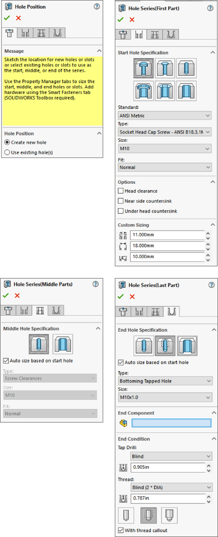
FIGURE 18.18 The Hole Series interface
BASIC HOLE SERIES STEPS
When using the Hole Series feature, you must follow these basic steps:
- Have an assembly open with two or more parts that need to be fastened together.
- Initiate the Hole Series tool by choosing Insert ➢ Assembly Features ➢ Hole ➢ Hole Series. It's also available as a toolbar button, but it isn't on the toolbar by default.
- If the Hole Series is to be started from an existing hole, select it in the Hole Position panel. If not, use sketch points, construction geometry, dimensions, and sketch relations to locate the hole centerpoints.
- Use the tabs at the top of the PropertyManager to advance from one panel to the next.
- The Start Hole Specification refers to the part where the series of holes starts.
- The Middle Hole Specification is for all parts between the first part and the last part.
- The End Hole Specification is the last part and is either a through clearance hole or a threaded hole.
The finished feature leaves an in-context feature in each part, with the Hole Series part in the assembly, as shown in Figure 18.19.

FIGURE 18.19 The finished Hole Series
Creating Weld Beads
![]()
![]() Weld beads are covered in Chapter 36, “Creating Weldments and Weldment Drawings,” but the assembly feature side of weld beads is covered here from a slightly different perspective. Although the SolidWorks Help refers to a Fillet Weld Bead feature, there is actually a difference between the Fillet Bead tool and the Weld Bead tool. The icons are similar, but the one with the bigger weld is the Fillet Bead. Both can be found on the Weldments toolbar, but only the Weld Bead can be found on the Assembly Features menu or flyout toolbar.
Weld beads are covered in Chapter 36, “Creating Weldments and Weldment Drawings,” but the assembly feature side of weld beads is covered here from a slightly different perspective. Although the SolidWorks Help refers to a Fillet Weld Bead feature, there is actually a difference between the Fillet Bead tool and the Weld Bead tool. The icons are similar, but the one with the bigger weld is the Fillet Bead. Both can be found on the Weldments toolbar, but only the Weld Bead can be found on the Assembly Features menu or flyout toolbar.
When comparing the functionality in the Weld Bead and Fillet Bead features, even the SolidWorks Help for the Fillet Bead recommends using the Weld Bead tool instead of Fillet Bead to insert weld beads.
The Weld Bead feature offers some advantages over the Fillet Bead feature:
- The same interface is available in parts and assemblies.
- It has a minimal effect on the performance of even a large number of weld beads.
- A basic weld symbol is created and applied automatically.
- It works with weldable gaps.
- The Smart Weld Selection tool speeds up selection significantly.
- Weld properties serve to evaluate mass, production time, and cost.
- Weld information can be pulled onto drawings.
To be clear, the Fillet Bead feature is only for weldment parts, and it creates a body with additional volume. The Weld Bead feature is for weldments and general assemblies, and it creates a cosmetic display body, not something that affects mass properties.
The workflow to create a weld bead is as follows:
- Select the weld path(s). The weld path can be a set of edges (they must be between two bodies or parts) or a set of faces (they must be from adjacent parts).
You can select multiple weld paths, and the paths don't need to touch. The weld path appears as bright pink for an active path or orange for an existing path listed in the PropertyManager.
The Smart Weld Selection tool creates new weld paths automatically based on your selections, and it greatly simplifies face or edge selection for weld bead creation. Just roughly sketch with the pencil where you want the weld to go, and SolidWorks will automatically select the faces or edges to make that weld happen.
- Set the size of the weld.
- Define the weld symbol that includes all the details about the weld for the welder on the drawing.
- Set the length limit of the weld.
- Establish requirements for an intermittent weld from the options given.
The PropertyManager for a weld bead made in a multibody part is shown in Figure 18.20.

FIGURE 18.20 Creating a weld bead
Notice that the welds are organized by size and type within the Weld folder. Fillet Weld is the default weld type if you don't specify another type.
The PropertyManager looks the same for the weld bead done in a multibody part as it does in an assembly. The results also look the same. Aside from the duplicate names, none of this has anything to do with the Fillet Bead feature that is available only in weldment parts.
To edit the weld bead, you must right-click the Weld Bead item listed under the size of the Fillet Weld in the Weld folder. This brings you back to the original Weld Bead PropertyManager.
You can manage other weld properties by right-clicking the size of the weld and selecting the Properties option. The Weld Bead Properties dialog box appears, as shown in Figure 18.21.

FIGURE 18.21 The Weld Bead Properties dialog box enables you to set many options.
Working with Envelopes
Envelopes in SolidWorks are regular parts or subassemblies that are used for selection or for reference. They are display-only items. You can make selections based on whether other parts are inside, outside, or crossing the envelope boundary. You can make an envelope in place in the assembly, or you can make an envelope from an existing part. Envelope parts don't count toward BOM part counts or material properties.
To insert an envelope, you must first insert a regular part and then designate it as an envelope. The two places to do this are in the Insert Component PropertyManager and the Component Properties dialog box, as shown in Figure 18.22.
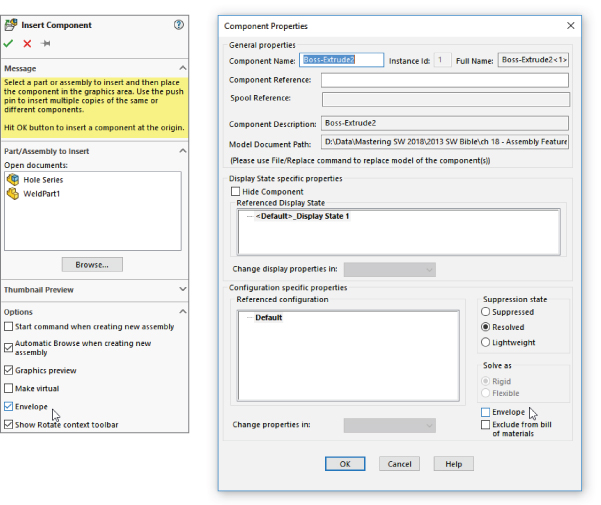
FIGURE 18.22 Inserting a new envelope into an assembly
Once in the assembly, the envelope displays in the graphics window as a transparent light-blue part and in the assembly FeatureManager as an Envelope folder.
The two options that the Envelope function was meant to work with—Select Using Envelope and Show/Hide Using Envelope—are shown in Figure 18.23. You can access these options by right-clicking the Envelope from the FeatureManager or the graphics window and then selecting Envelope.

FIGURE 18.23 Using the Envelope options
Component selection also includes a Volume Select function that enables you to create a rectangular volume on the fly that works very much like an envelope.
Envelopes can be external or virtual components.
Envelopes can also be shown in a drawing view, from the View Properties interface. They show up as phantom lines by default, although there are easier ways to show parts as phantom on a drawing, simply use the Component Line Font tool.
Understanding Smart Components
A Smart Component can comprise several elements:
- A single part or an assembly that may use size configurations
- A configurable library feature that usually serves as mounting holes or an opening for the Smart Component
- Associated hardware that may also be driven by size configurations
- A training assembly that is used to define the Smart Component
As you might expect, some minor limitations exist:
- A Smart Component part cannot have references that are external to the Smart Component group of which it is a member.
- When placed in the assembly, the associated library feature can affect only one component.
- The associated library feature is limited to these feature types:
- Extruded or revolved cuts or bosses
- Hole Wizard holes
- Simple hole features
The setup time for Smart Components can be significant for the first one or two that you create, especially if you use the auto-size option. The complexity of the setup depends mainly on the number of configurations and configured parts that you use. The auto-sizing function takes the most time to set up because it requires matching configurations, and the auto-size table takes a while to manage, especially for multiple parts. Still, if you end up placing a given part with associated features and other components many times manually, or if there are others in your group that do, this technique can save you and your team lots of time.
Using Smart Components
![]() A Smart Component is a library part or set of parts that needs to mate to features in another part. The Smart Component brings those features with it when it is placed in the assembly. You can access the Make Smart Component command in the Tools menu or in the toolbars; it is with the Assembly tools, although it may not be on the Assembly toolbar by default.
A Smart Component is a library part or set of parts that needs to mate to features in another part. The Smart Component brings those features with it when it is placed in the assembly. You can access the Make Smart Component command in the Tools menu or in the toolbars; it is with the Assembly tools, although it may not be on the Assembly toolbar by default.
Figure 18.24 shows a simple assembly. It took approximately 20 minutes to model all the parts, set up the Smart Component, and test it in an assembly. This example doesn't use auto-sizing, but it does use a library part, an in-context feature, and two instances of a single hardware piece. This is an excellent example of Smart Component functionality because it is fast to create and apply, and it saves you time whenever you use it.

FIGURE 18.24 A simple Smart Component
Getting Started with a Simple Smart Component
In this assembly, you first place the electrical connector part in the assembly, mate it in place, and then apply Smart Components. You can apply Smart Components by clicking the Smart Component icon that appears on the part in the graphics window when you select it. SolidWorks then prompts you to select the inside and outside faces of the sheet metal part (the hardware references the outside, and the cutout feature references the inside). SolidWorks then creates the cutout as an in-context feature that it places in the sheet metal part.
When you create the Smart Component, a new folder is added to the FeatureManager of the component. This folder contains all the required information about the other elements, such as the in-context feature, any other parts that go with the Smart Component, the “training assembly” location, and the face references to locate everything. The left image in Figure 18.25 shows this folder in the connector part that is used in this example. The right image shows what is added to the assembly FeatureManager when you add a Smart Component. The only thing that existed in the design tree shown in Figure 18.25 before the Smart Component was the Test Box sheet metal part.
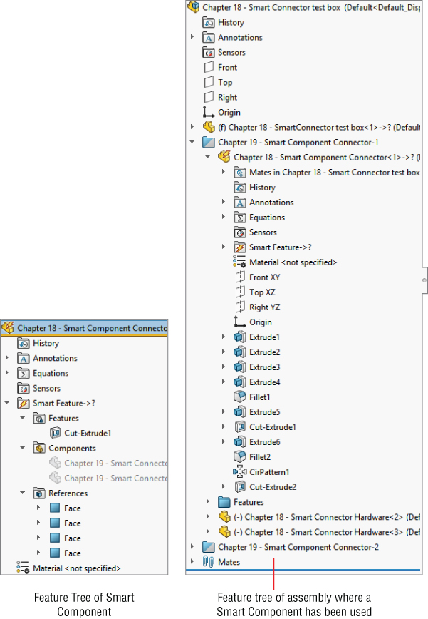
FIGURE 18.25 The Smart Component folder in the connector part
A thunderbolt appears on the part symbol at the top of the FeatureManager, indicating that the part is a Smart Component. You can place this Smart Component by following these steps:
- Create an assembly and add the target part to it. The target part is the one that the Smart Component will be mated to and the one that will have the in-context cutout inserted into it. In this case, the target part is a sheet metal
- Put the Smart Component into the assembly. You can do this in the same way that you would add any normal part, including one from the Design Library. If you use a part frequently enough to make it into a Smart Component, then you may want it in the Design Library for quick access. In fact, you can add a Smart Component to an assembly without using any of the Smart Component options.
- Mate the Smart Component in the assembly. In this case, it's done with a face-to-face coincident mate and a pair of distance mates.
- Apply Smart Components by clicking the Smart Component symbol on the part. Select the part in the FeatureManager to make a small lightning bolt appear on the part, as shown in Figure 18.26. Alternatively, you can select Insert Smart Features from the RMB. If you insert many instances of a Smart Component, then each instance will have the option to apply the Smart Component features and associated components. At this point, an interface similar to that of the Library Feature interface appears, with the small prompt window and a box for selecting references, as shown in Figure 18.27.
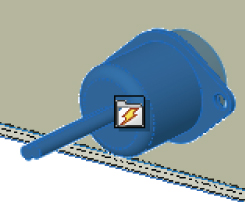
FIGURE 18.26 The Smart Component symbol on a part

FIGURE 18.27 The interface for adding the Smart Feature and additional components of the Smart Component
- Select the references and click the green checkmark icon. Then place the Smart Component, as well as the Smart Feature (in-context feature) and associated hardware components, to complete the job. You can rotate the part in the small preview window to get a better look at the part.
Auto-Sizing Smart Components
Auto-sizing is the capability of a Smart Component to automatically select a size from a list of configurations based on the size of the geometry onto which it is being dropped. At this time, the only shape that can be auto-sized is the cylindrical shape.
Figure 18.28 shows the effects of auto-sizing. Notice the two shaft holders. These are two instances of the same part, using different size configurations. When you drag the Smart Component over the small end of the stepped shaft, the configuration corresponding to that shaft size appears. As you drag the part along the shaft and the shaft diameter increases, the next-larger Smart Component configuration appears. This is part of the functionality of Smart Components. Each configuration of the Smart Component is set up to fit onto a range of shaft diameters. If the diameter of the shaft is outside of the range or between sizes, then the Smart Component is not applied.

FIGURE 18.28 A Smart Component with auto-sizing
Sizes are governed by a configurator table, which looks similar to a design table but works somewhat differently. The configurator table relates the configurations of the Smart Component to configurations of the individual parts, which may also change size with the Smart Component. This serves as a subset of the function of a design table in an assembly, assigning part configurations to assembly configurations. Figure 18.29 shows a sample configurator table made for the assembly shown in Figure 18.28.
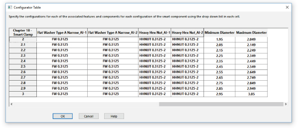
FIGURE 18.29 A configurator table
When you look at this table, you can begin to understand why creating auto-sizing Smart Components is much more involved than the first example in this chapter. The configurations of the Smart Component are listed to the left, and you can select the individual part configurations in each cell from a drop-down list of all available configurations for that part. There's no way to set the configurations for multiple components at once, nor is there a copy-and-paste function. These shortcomings combine to make this format less user-friendly than an Excel-based design table.
Most notable are the Minimum Diameter and Maximum Diameter columns to the right. These columns supply the parameters that make the auto-size function work. SolidWorks understands that mating sizes are not always exactly equal, and the ability to use a range rather than exact values (minimum and maximum diameter columns) accommodates this limitation very nicely, although it can be tedious to set up.
Another aspect of the setup shown here is that it uses Toolbox parts. If you want to use the auto-size functionality, then you need to be using configurations for Toolbox parts. You should prebuild all the needed configurations and ensure that they are always available.
![]() The Auto Size capability, as well as the creation of the configurator table, is triggered by the Auto Size panel in the Smart Component PropertyManager. To access the PropertyManager, click the Make Smart Component icon in the Assembly Command Manager or use the Tools menu in an open assembly document.
The Auto Size capability, as well as the creation of the configurator table, is triggered by the Auto Size panel in the Smart Component PropertyManager. To access the PropertyManager, click the Make Smart Component icon in the Assembly Command Manager or use the Tools menu in an open assembly document.
To edit the Smart Component, follow these steps:
- Open a Smart Component in its own window.
- Right-click on the Smart Feature folder.
- Select the Edit In Defining Assembly option.
- (At the upper-right of the graphics window, there will be a small box with a button that says Edit Definition.) Click Edit Definition.
- This will bring up the Smart Component PropertyManager from which you can access the configurator table and other defining features.
Making Smart Components
The most important point to remember about Smart Component setup is that you need to do it only once for each Smart Component. The second most important point is that the first setup is the most difficult. After that, subsequent setups become much easier to create. Adding components to the Smart Component isn't so time-consuming unless the additional components are also configured and auto-sized.
Smart Components must contain at least one associated component and one in-context feature, or the configurator table must be filled out and functional. If you try to create a Smart Component from a stand-alone part, nothing happens; the Smart Component interface simply closes because there's nothing for it to do. You may combine all three elements (associated component, in-context feature, and auto-size), but you must have at least one element.
Getting Started with a Simple Smart Component
Because the electrical connector shown in Figure 18.27 was already used to demonstrate the insertion of a Smart Component, it's used here to demonstrate how to create one.
All that you need to make a Smart Component with an associated Smart Feature (in this case, a cutout and mounting holes) and mounting hardware (in this case, two stand-off screws) is the actual part. The part can even be imported (a Smart Component made from dumb geometry). This example uses the file named Chapter 18 – Connector Start.sldprt from the Chapter 18 folder.
There's nothing special about this part. It's modeled in SolidWorks using standard features, and there are no configurations or special features. It could have been downloaded from 3D Content Central. It represents an electrical connector that may be mounted in a sheet metal electrical enclosure.
The first step in setting it up is to create a mock assembly with a dummy part representing the sheet metal box. The part doesn't need to be complex—or even sheet metal for that matter; it just needs to be close to the thickness to which you would expect the Smart Component to be mounted. The assembly is called a training assembly, not because you are learning how to make a Smart Component, but because you are training the Smart Component to be smart.
- Open the part
Chapter 18 – Connector Start.sldprtfrom the materials downloaded from the Wiley website. - Make a simple rectangular part, approximately 4 inches square and about .06 inch thick. Save the part to your hard drive. Give a name to the part so it's clear that it belongs to this training assembly.
- Place the rectangular dummy part into a new assembly, with a name that is both unique and identifiable.
- Put the connector into the assembly. Mate the part so the flange is flush with the rectangular piece. Also use distance mates to locate the connector planes from the edges of the part, similar to Figure 18.30 in the image to the left.
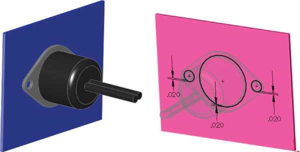
FIGURE 18.30 Placing the connector on the dummy part
- Edit the dummy part in context (right-click the dummy part in the assembly and select Edit Part), and offset edges of the connector part to extrude a cut, as shown in the image to the right in Figure 18.30. Offset the two mounting holes and the area around where the connector will stick through the sheet metal by about .02 inch.
- Exit Edit Component mode and add two instances of the part named
Chapter 18 – Smart Connector Hardware.sldprtto the assembly. Mate the hardware part to the in-context hole, making sure that it goes to the outside thickness of the dummy sheet metal part.  Now that everything is in place, click the Make Smart Component tool on the Assembly toolbar. If the button is not there, you can add it to the Assembly toolbar by choosing Tools ➢ Customize Menu or by choosing Tools ➢ Make Smart Component. The resulting interface is shown in Figure 18.31.

FIGURE 18.31 The Smart Component PropertyManager interface
- In the Smart Component selection box, select the connector part.
- In the Components selection box, select the two hardware components.
- In the Features selection box, select the in-context feature from the dummy part. You are now finished setting up the Smart Component.
- Click the green checkmark icon to accept the changes, exit out of the PropertyManager, and save the file.
Creating an Auto-Sizing Smart Component
The simple Smart Component took about 20 minutes to model and set up. That's not too bad for a feature that you will probably use often. The benefits are somewhat modest, placing three components and a feature.
However, when it comes to the auto-sizing example that is shown next, the benefits are more extensive. A total of seven individual parts are placed (including Toolbox parts)—three of which are automatically sized, depending on the geometry into which the Smart Component is dropped—and an in-context feature is added.
To begin, open the part from the website download materials named Chapter 18 - Clamp Start.sldprt. Notice that this is a multibody part. You don't need any special knowledge about multibody parts to complete this task. Multiple bodies are discussed in detail in Chapter 31, “Modeling Multibodies.”
- With the Clamp Start part open, click through the configurations or examine the design table in the part; you can see that various dimensions change. Notice that several configurations already exist. The primary dimension that changes is the diameter of the hole, and this change drives the diameter of, and distance between, the mounting holes.
Part of the Smart Component definition includes applying a Mate Reference to the part so that the big hole automatically snaps to cylindrical geometry. Another aspect is that it adds in-context holes that match the mounting holes to the plate. Figure 18.28 shows the assembly into which this part is meant to go. The clamp snaps onto the stepped shaft and adds holes to the plate.
- Open the file named Ch
apter 18 Autosize Training Assembly.sldasm. This has been prepared to help you get started with the Smart Component training. - Insert the clamp part into the assembly, and mate it concentric to the shaft and coincident to the blue plate. It does not matter where the clamp sits along the shaft, but it should be fully mated into the location so it doesn't slide back and forth. A distance mate from a plane or planar face would be a good choice.
- Edit the plate in the context of the assembly, and convert entities from the mounting holes in the clamp to create holes in the plate that align with the holes in the clamp.
- Exit Edit Component mode.
- Activate Toolbox, select the four holes, as shown in Figure 18.32, and insert Socket Head Cap Screws
 inch. If you do not have Toolbox or choose not to use it, then you can use the part with the correct name and correctly sized configurations that is provided in the website download material.

FIGURE 18.32 Inserting four screws at once using Toolbox
- Use the same fastener to place in the mounting holes, using the correct size for the holes. You will set the length later. Use a default length of 2.25 inches for both mounting holes.
- Place washers and nuts on the screws on the backside of the plate.
- When the shaft diameter changes, the hole in the clamp changes to match (within the ranges that you will establish). As the clamp becomes larger, bigger screws are needed to secure the clamp and the holes grow farther apart. Bigger screws mean additional configurations for the screw, washer, and nut parts. Remember that the configurations do not necessarily exist. You should not count on a Smart Component working if this means that Toolbox must create new configurations.
In this example, the Toolbox parts are prepopulated with all the configurations needed for the range of sizes involved with this Smart Component. When you make your own Smart Components, you must do the same thing if you intend to use auto-sizing with Toolbox parts. The difficulty here is that the configurations include the diameter size of the screw as well as the length, which is unknown until you place the part.
For this step, you must make sure the configurations are available and the screws are placed properly.
Up to this step, you have just assembled the parts as if this were the only time you were going to do it. The automation of the process comes next. Figure 18.33 shows the training assembly to this point. The shaft and plate are shown in wireframe because they are external to the Smart Component.
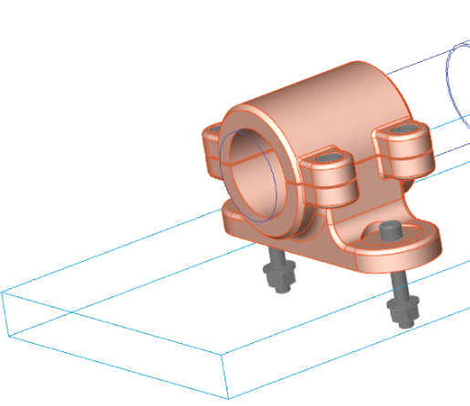
FIGURE 18.33 The training assembly up to step 9
- Click the Make Smart Component tool on the Assembly toolbar. In the previous example, this was the point where the Make Smart Component command was used, and it's no different here.
- Activate the Smart Component selection box and pick the clamp part. Figure 18.34 shows the filled-in Smart Component PropertyManager.
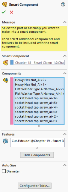
FIGURE 18.34 The Smart Component PropertyManager
In the Components selection box, select the six screw instances, the two washers, and the two nuts.
In the Features selection box, select the in-context feature or features that are associated with the Smart Component.
The configurator table is simply a table that enables you to select which component configurations are to be used with which Smart Component configuration. It looks and works very much like an assembly design table, but it is not Excel-based, and every cell must be set explicitly rather than using techniques for mass population or assigning properties to a range of configurations, as you can do with a real design table.
Each cell has a drop-down list of all the available configurations for that component. If you have four instances of a single component, then you must set each instance of each component. Figure 18.35 shows the configurator table for this example.
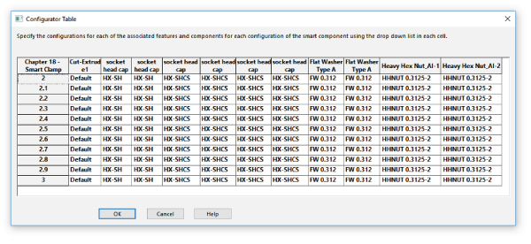
FIGURE 18.35 The configurator table for the Clamp Smart component
- Click OK. You are now done creating the auto-sizing Smart Component.
Managing Files with Smart Components
You might expect that with the training assembly, there's an extra burden of file management with Smart Components. This may seem counterintuitive, but in fact, the only file you need to worry about is the actual Smart Component.
Although this isn't explained very well in any of the documentation, the Help and reseller demonstrations on the topic generally recommend that you simply delete the training assembly after you're done with it because it's not needed any more. It turns out that all the information to re-create the training assembly is stored in the Smart Component. This includes the in-context feature (which is stored as a library feature) and the locations of any associated components, as well as the configurator table. Figure 18.36 shows a part of the FeatureManager of a Smart Component. As you can see, the in-context feature, the associated components, and the face references are all listed there.
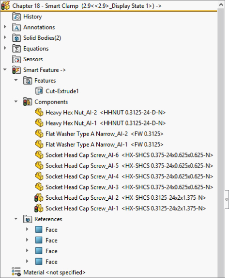
FIGURE 18.36 Part of the FeatureManager of a Smart Component
Deleting the training assembly does not cause any data to be lost; you will delete an assembly in the following section.
Editing Smart Components
Expanding on the discussion about whether to keep the training assembly file, here's a little exercise that you can try. Make a Smart Component by going through the preceding steps, using the following tutorial or creating one of your own. Just make a simple Smart Component with perhaps one associated component and an in-context feature. Then delete the training assembly.
With the defining assembly gone, there appears to be no way to edit the setup of the Smart Component. Right-click the Smart Feature folder in the FeatureManager of the Smart Component, and select Edit In Defining Assembly, as shown in Figure 18.37. SolidWorks re-creates the defining assembly from the data that is stored in the Smart Component. This assembly is saved in a system temp folder using the name <Smart Component name>_ta.sldasm. If the Smart Component uses an in-context feature, it's saved to the temp directory as a library feature file using the name of the dummy part and appending _lf to the filename (for example, Dummy_lf.sldlfp).
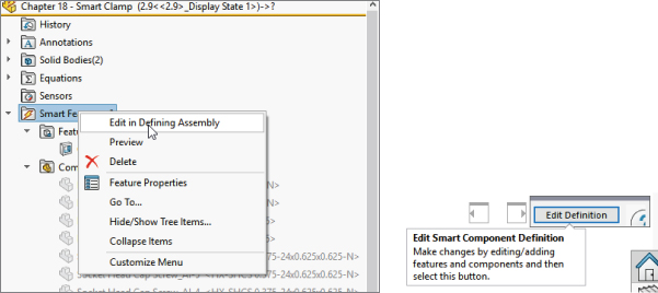
FIGURE 18.37 Selecting the Edit in Defining Assembly command
The Edit Definition button appears in the upper-right corner of the graphics window and is shown to the right in Figure 18.37. It covers the Close Document X. If you click this button, the Smart Component PropertyManager interface appears again, enabling you to change the selection of associated components and in-context features, to change the auto-size setting, or edit the configurator table.
Therefore, all the settings are preserved, and the training assembly exists only as a phantom in a temp directory. Although this appears to be counterintuitive, it works.
Tutorial: Working with Smart Components
This tutorial guides you through the process of creating a Smart Component that uses only the auto-sizing feature. This enables you to manually create parts that snap to size like Toolbox parts, but without using Toolbox functionality. Follow these steps:
- Open the part from the website download materials that has the filename
Chapter 18 – Tutorial Start.sldprt. This part originally came from Toolbox and already contains a few configurations. - Make an assembly that contains only this part.
- Make the part into a Smart Component (Tools ➢ Make Smart Component) and turn on the option to auto-size.
- Select the small diameter of the part as the concentric Mate Reference. Figure 18.38 shows the selection.
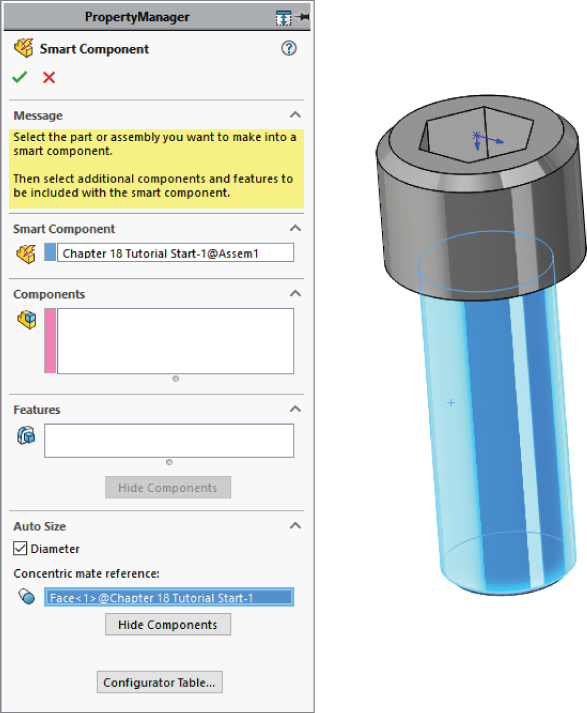
FIGURE 18.38 Selecting the concentric Mate Reference face
- Click the Configurator Table button and fill in the table so it looks like Figure 18.39. Some configurations are blank. This is because only the rows that have minimum and maximum values are used by the auto-size function. The rest are overlooked.
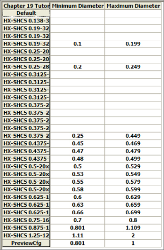
FIGURE 18.39 Filling in the configurator table
- Close the configurator table, click the green checkmark icon to exit the feature, and save the assembly.
- Exit the assembly, and in the part file, save it to a folder in your Design Library. If you do not know where your Design Library is located, choose Tools ➢ Options ➢ File Locations ➢ Design Library.
- Display the part in the Design Library panel of the Task pane.
- Open the part from the downloaded materials with the filename
Chapter 18 Tutorial Plate.sldprt. Place this part into a new assembly. - Drag the Tutorial Start (Smart Component) from the Design Library into the assembly and move the part over the holes in the plate. As you drag the part up and down the row of holes, the part changes size to match each hole. Figure 18.40 shows all the holes that are populated with the matching Smart Component sizes, as driven by the configurator table. Place the part over one of the diameters.

FIGURE 18.40 Smart Component parts match holes in the part.
- To edit the configurator table, open the Smart Component part in its own window. Then right-click the Smart Feature folder and select Open In Defining Assembly. An assembly that was created from the data stored in the part opens.
- Click the Edit Definition button that appears in the upper-right corner of the graphics window.
- Reassign the minimum and maximum diameter values for the
 -inch and
  -inch configurations to the shortest lengths. For example, the chart shows the
  -inch configuration to be assigned to a minimum of .1 and a maximum of .199. Move the .1 and .199 values up two cells to the
  -inch configuration. Do something similar for the
  -inch configuration. The edited part of the chart now looks like Figure 18.41.

FIGURE 18.41 The edited configurator table
Tutorial: Working with Library Features
This tutorial guides you through the process of customizing a Hole Wizard hole to use as a specialty library feature, storing it in the library, editing it, and placing it in a part. Follow these steps:
- Open a new part, and create a rectangular base feature, about 3 inches high by 3 inches wide and 3 inches deep.
- Preselect a flat face and start the Hole Wizard.
- Create a counterbored hole for a Heavy Hex Bolt, 1/2-inch, Normal Fit, Blind, 1.2 inches deep. Locate the hole with dimensions from two perpendicular edges, as shown in Figure 18.42. Click the green checkmark icon twice to accept the hole settings.
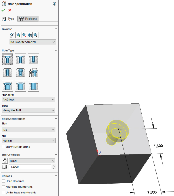
FIGURE 18.42 Placing a hole
- Turn on the setting at View ➢ Dimension Names.
- Double-click the counterbored hole feature in the FeatureManager to show the dimensions. Make sure Instant3D is unselected for the next step.
- Click one of the dimensions that you created to locate the center of the hole and rename the dimension in the Dimension PropertyManager (Primary Value panel) using names that will have meaning when you place the dimension, such as XDir or YDir. Do this for both dimensions.
- Edit the second sketch of the hole. Figure 18.43 shows what the sketch should look like before and after the edit.

FIGURE 18.43 Reconfiguring the hole
- When you are finished editing the sketch and renaming the dimensions, exit the sketch.
- Click the CBORE feature twice, or click it once and press F2 to rename it as SpecialHole.
- Preselect the same flat face that the first hole feature was placed on, and start the Hole Wizard again.
- Place a #8-32 tapped hole, accept the default depth, and specify a center-to-center distance of .75 inches between it and the SpecialHole in the Horizontal or Vertical direction. Rename the radial dimension as MountRad.
- Using a cylindrical face of the SpecialHole, make a circular pattern of the new tapped hole, creating a total of four instances of the tapped hole. Make the SpecialHole Feature red and the tapped hole and pattern yellow.
- Split the FeatureManager window into two by using the splitter bar at the top. Change the lower panel to the ConfigurationManager.
- Rename the Default configuration Size1.
- Create a new configuration called Size2. Double-click the SpecialHole feature, and change the dimension named C'Bore Dia to 1.5 inches. Be sure to change to This Configuration Only using the drop-down menu.
- Make a dimension change for the MountRad dimension to 1 inch. The results up to this step are shown in Figure 18.44.
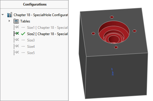
FIGURE 18.44 The results after step 16
- Auto-create a design table by choosing Insert ➢ Design Table and then selecting the Auto-Create option. Edit the design table to look like Figure 18.45. Hide or delete extra columns that don't match the data shown.

FIGURE 18.45 The design table for the SpecialHole feature
- Manually fill in the C'Bore Dia values, but in cell D3, type the equation =C3/2 + 0.25. Then use the same Fill technique to populate cells D3 to D7. Click outside of the design table to close it.
- Test the configurations to make sure they all work.
- In the Design Library, browse to a folder where you would like to put this library feature. (Make sure it's not used by any assemblies or sheet metal forming tools.) Click a face created by the SpecialHole feature, and drag the feature into the lower pane of the Design Library. The Add to Library PropertyManager should appear on the left.
- Although you selected a feature and dragged it into the library, the Items To Add field appears blank, so you must select the SpecialHole, tapped hole, and circular pattern features using Ctrl+select for multiple selections, either through the detachable PropertyManager, the split FeatureManager, or the flyout FeatureManager. Selecting the features from the graphics window won't work.
- Position and zoom the view of the part so that when it is saved, you see a good preview of the library feature. Also, if you have not changed your background color from blue to white, this would be a good time to do so.
- In the Save To pane, make sure you select the correct folder, and then fill in a filename and click OK. Figure 18.46 shows the completed PropertyManager interface for this function.
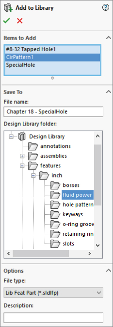
FIGURE 18.46 Saving the library feature
- If the new library feature does not appear in the Design Library, then click in the Design Library and press F5. If you don't like the way it displays, right-click in a blank space inside the lower library window and select one of the other three options.
- To edit the preview image of the feature, right-click the feature in the Design Library window, select Open, reposition or zoom the view, and save it. Click in the Design Library and press F5 again.
- From the download materials, open the part called
Chapter 18 Tutorial Blank.sldprt. If you would like to examine the version of the SpecialHole part that I created, it's saved asChapter 18 – SpecialHole.sldlfp. Notice that this is a library feature part file, not a regular SolidWorks part file. - Drag the SpecialHole library feature from the Design Library onto the face of the blank part. Place the feature near the squared-off end. Select a configuration from the list in the PropertyManager.
- Try to orient the part in the same way that it appears in the preview window, as shown in Figure 18.47.

FIGURE 18.47 Orienting the part and selecting references
- On the blank part, select edges that correspond to the preview window. Click OK to accept the placement of the feature.
- Double-click the SpecialHole feature, and change the X and Y placement dimensions to place it 1 inch from the edges in both directions.
- Place another library feature onto the blank part. Select a configuration and click the green checkmark icon without selecting edges for the references.
- Notice that the feature in the FeatureManager appears with an exclamation mark. If you investigate the cause of this, you will see that the two dimensions that should be attached to edges are dangling because you didn't select the references while placing the library feature. This was done on purpose to show a different technique.
- Expand the library feature and the SpecialHole feature, and edit the first sketch in the Special Hole. This is the placement sketch. Delete the two dimensions that appear in dangling colors.
- Add a concentric sketch relation between the placement point and the arc edge of the blank part, and exit the sketch. The error message should now be gone, and the hole should now be placed in the center of the arc.
- Right-click the second library feature and select Dissolve Library Feature. Figure 18.48 shows the finished part and FeatureManager. Good job!

FIGURE 18.48 The finished part
The Bottom Line
Assembly features can be quirky and are often used for specialized or niche applications. Having this functionality available gives you another tool in your toolbox for solving design and documentation problems.
The Hole Wizard can be a useful tool for placing machined holes through multiple parts. Automation is a great thing, and you should utilize it where it helps your process.
- Master It The most basic step in reusing data in the form of libraries is establishing the location of your libraries. Use the settings at Tools ➢ Options ➢ File Locations to do this. First, determine if you need local (on your computer) or network locations for these libraries.
- Master It Make sure you know where in your interface to find the Design Library and how to navigate its various elements.
- Master It Toolbox can be an integral part of using libraries with SolidWorks. Learning to manage Toolbox, however, may drive you to make the decision to create and manage your own library of standard parts. Make sure you have learned where the weaknesses of Toolbox are and how to work around those weaknesses.