
Chapter 28
Using Layers, Line Fonts, and Colors
This chapter addresses layers, line fonts, line colors, and other strictly 2D types of functionality within SolidWorks drawings. It's never productive to try to use SolidWorks as if it were AutoCAD, but sometimes there is an overlap in functionality. If you're making the transition from 2D to 3D, you will be much further ahead if you just embrace SolidWorks for what it is and accept that it doesn't work like a 2D-only program.
Controlling Layers
![]() Layers are available only in SolidWorks drawing documents, not in 3D modeling or even sketching at all. Even in drawings, layers have not traditionally been used a lot in the formal SolidWorks demo or training materials.
Layers are available only in SolidWorks drawing documents, not in 3D modeling or even sketching at all. Even in drawings, layers have not traditionally been used a lot in the formal SolidWorks demo or training materials.
Working with Layers in Imported 2D Data
When you import 2D data through DXF or DWG format files, the layers that exist in the original data are brought forward into SolidWorks, and you can use them in a similar way to the original AutoCAD usage. For example, you can turn layers on or off (visible or hidden), and you can change layer names, descriptions, color, line thickness, and line style.
The way you intend to use the imported data determines how you should open the file. If you only intend to view and print the drawing, then I would suggest using DraftSight, a free download from the Dassault Systèmes or SolidWorks websites. It offers a familiar interface for the AutoCAD user.
If you need to integrate data from the imported document into a native SolidWorks drawing, you can open the DWG file from the normal Open dialog box in SolidWorks.
The colors assigned to layers in data coming from AutoCAD are often based on a black background, so they can be difficult to see on a white background. SolidWorks does not have an automated tool that makes sure you have contrasting background colors. The two ways of dealing with this are to change the SolidWorks drawing sheet color to something dark or to change the individual layer colors to something dark. Both methods are easy, although if you have to send the 2D data back to its source, it might be best to temporarily change the drawing sheet color.
Figure 28.1 shows the layer interface with an imported drawing in the background. To open the Layers dialog box, click the Layer Properties button, which is found on both the Layer and Line Format toolbars.
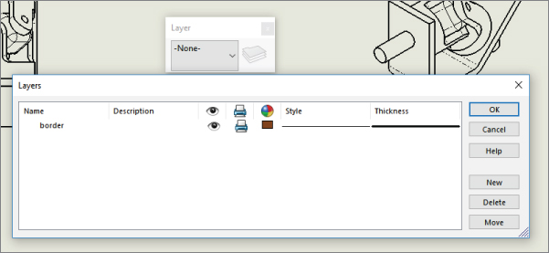
FIGURE 28.1 The Layers dialog box and the Layer toolbar
Be aware that many items in an imported drawing may come into SolidWorks as blocks. These items may need to be exploded before you can work with them. This is often the case with the drawing border, title block, or format. To explode a block, right-click the block and choose Explode.
Working with Layers on the Sheet Format
One of the most obvious uses of layers is for the drawing border sketch lines on the sheet format. The sketch lines used to create the border often have a heavier line weight and a different color that easily distinguishes them from model geometry.
You can assign layers in three ways:
- Select existing items, and then select a layer from the drop-down list on the Layer toolbar.
- Set the active layer and create new items.
- While creating items such as sketch entities and annotations, select the layer for the new entity directly from the PropertyManager.
To set a layer to the active layer, double-click it from the Layers dialog box (refer to Figure 28.1) or change it from the drop-down list on the Layer toolbar. When you assign an active layer, other newly created entities are also placed on the layer, not just sketch entities. Symbols, annotations, blocks, and other elements can also be put onto layers. If you're not particular about the layering scheme on a drawing, then it may be advisable to set the active layer to None, which is a valid option in the Layer toolbar drop-down list.
When you create a new layer in SolidWorks, the new layer becomes the active layer, and any new items that are added are automatically placed on that layer.
Another option when building a sheet format, or any other drawing function that requires sketching, is to use a special layer for construction geometry. This will enable you to hide the layer when it isn't being used, but it will still maintain its relations. Hidden layers can be used in several other ways (for example, as standard notes on the drawing), and they can be easily turned on or off.
Adding Dimensions and Notes to Layers
SolidWorks drawings have a tendency to be drab black-and-white drawings in contrast to AutoCAD drawings, which often seem to take on a plethora of contrasting colors. Drawings are often easier to comprehend when different types of items are colored differently, but to do this effectively, you must apply the coloring scheme consistently. Dimensions and annotations can also be placed on layers in the three ways described in the preceding section (active layer, from the PropertyManager during creation, and through the drop-down list on the Layer toolbar). However, the line styles don't affect dimensions and notes, only the color and visibility settings.
Working with Components on Layers
Assembly drawings probably suffer the most from the monochromatic nature of most SolidWorks drawings because individual components can be difficult to identify when everything is the same color. This is why SolidWorks users typically color parts in the Shaded Model assembly window. It makes sense that they would want to do the same thing on the drawing.
USING ASSEMBLY COLORS ON DRAWINGS
You can use assembly part colors on drawings. This is a document-specific setting, so it applies only to the documents where you want it to apply, not to all drawings, unless you have saved the setting in a template. If you use this setting, you may also need to be more careful in how you choose part colors in your assemblies. You will generally want to choose darker and more saturated colors, and avoid the yellows, grays, and light colors that won't contrast with the white or gray color of the default SolidWorks drawing sheet.
You can find the setting to use assembly part color on your drawing at Tools ➢ Options ➢ Document Properties ➢ Detailing ➢ Use Model Color For HLR/HLV In Drawings. HLR stands for hidden lines removed, and HLV stands for hidden lines visible. These are the two Wireframe display modes that are most frequently used on drawings. Of course, another way to display part color on drawings is to use shaded views, but for traditional drawings, shaded views are often considered nonstandard. Figure 28.2 shows the setting in the Document Properties dialog box.

FIGURE 28.2 Using assembly part colors on your drawing
The setting mentioned for Shaded drawing views is available by selecting the view on the drawing and clicking the Shaded Display Style toolbar icon from the Heads-Up View toolbar on the drawing or from wherever the View toolbar is displayed. You could do the same thing by selecting the view and then choosing View ➢ Display ➢ Shaded or Shaded With Edges.
USING ASSEMBLY PARTS ON LAYERS
Another option to display the components of an assembly in different colors while using a Wireframe display mode that doesn't rely on colors assigned to parts in the assembly is to use the Component Line Font options. (Line fonts are covered in this chapter, in the section “Controlling Line Format.”) The Component Line Font dialog box contains a Layer setting, which you can use to put a part on a layer. If the layer is set up with a color, the part will display with that color in all views of the drawing or in just the current view, depending on your settings. It takes some time to set up the individual layers for each part and then to set the parts to the layers.
You can access the Component Line Font dialog box by right-clicking a component in a drawing view. The Component Line Font dialog box is shown in Figure 28.3.

FIGURE 28.3 The Component Line Font dialog box
In normal use, the Use Document Defaults option is selected and all the settings in the dialog box are grayed out. To gain access to these settings, you must deselect the Use Document Defaults option, as shown in Figure 28.3.
Controlling Line Format
![]() The Line Format toolbar contains the Layer tool and four additional tools that control lines: Line Color, Line Thickness, Line Style, and Color Display Mode. There is no actual setting or tool called line format. These settings can be controlled separately from layers; therefore, they can be used in model sketches as well as on drawings. In the model, the line font can be displayed only for inactive sketches. Any sketch that is both closed and shown can be displayed with the Line Format settings.
The Line Format toolbar contains the Layer tool and four additional tools that control lines: Line Color, Line Thickness, Line Style, and Color Display Mode. There is no actual setting or tool called line format. These settings can be controlled separately from layers; therefore, they can be used in model sketches as well as on drawings. In the model, the line font can be displayed only for inactive sketches. Any sketch that is both closed and shown can be displayed with the Line Format settings.
Figure 28.4 shows the Line Format toolbar along with the interfaces for Line Color, Line Thickness, and Line Style.
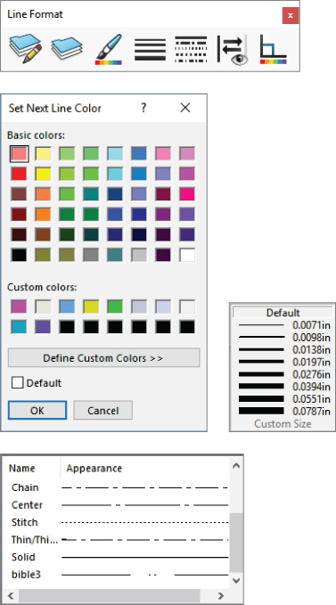
FIGURE 28.4 The Line Format toolbar and related interface options
Using the Line Format Settings
You can specify the Line Format settings using two different methods. In the first method, you can set them with nothing selected, in which case they function like System Options (the new setting takes effect for all documents that are opened on the current computer). In the second method, if they are set with sketch entities or edges selected, then the settings apply only to the selected entities.
Setting the End Cap Style
Another option for the Line Font settings is the End Cap Style. This offers an important option, especially for thick lines. The three options are flat, round, and square. Of these, the square style is usually most appropriate. To find this setting, choose Tools ➢ Options ➢ Document Properties ➢ Line Font. You may want to change this setting and update your drawing template files.
Figure 28.5 shows the difference between the three options of End Cap Style.
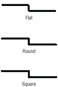
FIGURE 28.5 The End Cap Style setting options
Notice the small notches at the sharp corners of the flat style. These can be very distracting on a drawing and, in my opinion, they don't look very professional. This notched effect is most pronounced on thicker lines.
Setting the Line Thickness
The Line Thickness settings are Default, Custom, and eight width settings. Interestingly, the different thicknesses are named in the interface where you set the actual thicknesses, but not in the interface where you set lines to thicknesses. Figure 28.6 shows the Line Thickness page (Tools ➢ Options ➢ Document Properties ➢ Line Thickness).
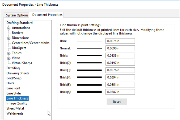
FIGURE 28.6 The Line Thickness settings in Tools ➢ Options
The way the line thickness is shown in the drawing has nothing to do with the numerical width that is assigned to it. For example, in Figure 28.6, notice that Thick(2) is set to 0.0197 inch, which is much wider than Thick(3), which is set to 0.0276 inch in this case. Changing the numbers affects only printed line thickness; it doesn't affect the display at all.
Setting the Line Style
You can create custom line styles using the syntax shown on the Line Style page (Tools ➢ Options ➢ Document Properties ➢ Line Style). This is a document-specific setting; therefore, if you make a custom line style and want to use it in another document, you have to save it (as a *.sldlin file) and load it into the other document. Also, if you save your templates with this line style loaded, you won't have to load the styles for any document made from that template.
Changing the Color Display Mode
![]() Color Display mode toggles between the display of assigned colors and standard sketch state colors. This is primarily used in drawings when you're making sketches where sketch relations are important. This setting is used to control the display of sketch entities only.
Color Display mode toggles between the display of assigned colors and standard sketch state colors. This is primarily used in drawings when you're making sketches where sketch relations are important. This setting is used to control the display of sketch entities only.
Hiding and Showing Edges
![]() Sometimes, for illustrative purposes, it's desirable to hide certain edges in drawing views. The Hide/Show Edge button is on the Line Format toolbar, although it may not be on the toolbar by default. You can choose Tools ➢ Customize to put it on a toolbar. To display an edge after it has been hidden, right-click where it should be and use Hide/Show Edge from the RMB menu.
Sometimes, for illustrative purposes, it's desirable to hide certain edges in drawing views. The Hide/Show Edge button is on the Line Format toolbar, although it may not be on the toolbar by default. You can choose Tools ➢ Customize to put it on a toolbar. To display an edge after it has been hidden, right-click where it should be and use Hide/Show Edge from the RMB menu.
To use the Hide Edge tool, simply select the edges you would like to hide and click the Hide Edge button. To show the edges, click the Show Edge button; the hidden edges will display in orange. Selecting them at this time will display them when the command is complete.
Be aware that if your view is in Draft Quality, any edges you hide will still be shown until the view is made into a High Quality view. Also, be aware that child views may take on the display properties of their parent views, so you may have to set the main view to High Quality before the hidden edges will display (or not) properly.
You might also want to be aware of a setting under Tools ➢ Options ➢ Drawings ➢ Automatically Hide Components On View Creation. This setting hides components that are not visible in the view. Although it doesn't intuitively make sense, it allows SolidWorks to save time calculating hidden edges by simply hiding the entire component. This can save a lot of time; however, if you're not aware of what's happening and are not accustomed to looking in the Hide/Show Components area for hidden parts that were hidden automatically, it can lead to some frustration if the view changes or you add a break-out view, and the automatically hidden parts suddenly become visible. There is no automatic function to unhide these components.
Tutorial: Using Drawing Display Tools
Some of the functions described in this chapter are difficult to understand until you actually use them. This tutorial guides you through the functions step by step so you can see them in action. Start here:
- From the download material, open the drawing called
Chapter 28 – Tutorial.slddrw. Make sure that the Layer and Line Format toolbars are active and that the Hide/Show Edges buttons are available on the Line Format toolbar. - Right-click a blank space and select Edit Sheet Format from the menu.
- Window+select (or Ctrl+A) everything on the format, and use the drop-down list on the Layers toolbar to assign the selection to the Border layer. Notice that this changes the color and the thickness of the sketch lines.
- Right-click a blank space and select Edit Sheet.
- Click the Layer Properties button on either the Layer or Line Format toolbar. Add new layers for each of the part groups, bracket, clevis, pins, and blocks, assigning different colors to each layer. Figure 28.7 shows the Layers dialog box with these layers created. Assign a different color to each new layer, preferably something that will contrast against white.
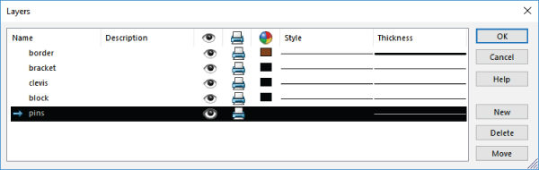
FIGURE 28.7 The Layers dialog box
- Set the active layer to None in the Layer toolbar drop-down list and exit the Layer dialog box.
- Right-click the Bracket part in one of the views and select Component Line Font. Deselect the Use Document Defaults option and select the Bracket layer from the drop-down list in the lower-right corner of the dialog box, as shown in Figure 28.8. Make sure that the Drawing View option is set to All Views.
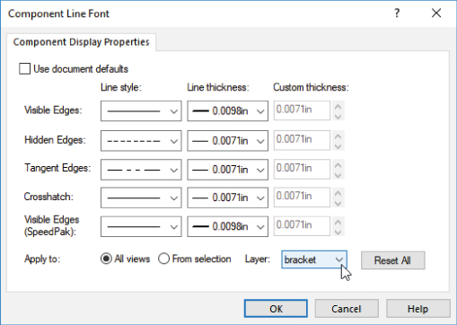
FIGURE 28.8 The Component Line Font dialog box
- Repeat step 7 for all the components, assigning each component to its own layer. Notice how this makes the parts easier to identify.
- Open the Component Line Font dialog box for the Bracket part again. This time, set the Line Thickness to 0.0787 and click OK. You may have to rebuild the drawing to show the change (Ctrl+B or Ctrl+Q). Figure 28.9 shows a detail of the corners that are created by the thick lines.
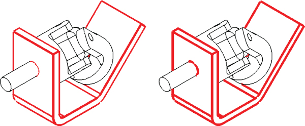
FIGURE 28.9 Applying thick edges
- Notice the notches created at the corners. These notches are supposed to be fixed using the End Cap setting at Tools ➢ Options ➢ Document Properties ➢ Line Font. Set the End Cap Style to Square. Click OK to exit the Document Properties. In the drawing, select inside the view where you are working, and make sure it's set to High Quality. (The setting is found in the PropertyManager for the view in the Display Style panel. If it's already set to High Quality, there will be no other view option; if it isn't, there will be an option that is set to Draft Quality.)
The image to the left in Figure 28.9 is the old setting with the Draft Quality view, and the image to the right is the new setting with the High Quality view.
- In the Component Line Font dialog box, set the Line Weight setting back to Default for the Bracket part, but keep it on the Bracket layer.
- In the isometric view, Ctrl+click all the tangent edges on the Bracket part, as shown in Figure 28.10. Click the Hide/Show Edges button on the Line Format toolbar.
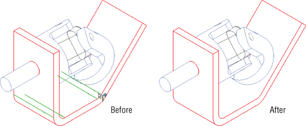
FIGURE 28.10 Hiding edges
- Click the Hide/Show Edges button. The PropertyManager message will change to indicate that you can select Hidden Edges, and the hidden edges will display in orange. Ctrl+select the hidden edges and right-click when you are finished.
The Bottom Line
Although SolidWorks is not primarily built around the strength of its 2D drawing functionality, it offers more capabilities than most users take advantage of. Layers, colors, and line styles can make your drawings clearer and easier to read.
- Master It Create a new drawing from the part called
Sample Casting.sldprtin the downloaded materials for this chapter. Make a drawing of it and import the dimensions automatically.Create a new layer called Dimensions and move all the dimensions to it using box select or the selection filter to help.
Set the color to the new dimension layer as dark blue.
- Master It Create several new annotations and place some blocks from the library.
Create a new layer for annotations and move these entities onto it.
Change the color of the new layer to dark green.
Leave the Annotations layer as the active layer and create a new annotation.
- Master It On the Sample Casting drawing, select a couple of interior edges and hide them using the Hide/Show Edges.
Next select a couple of exterior edges and change the line font to a thicker style.