
Chapter 33
Employing Master Model Techniques
In this book, the term master model refers to a technique where an entire assembly is laid out or has its major faces constructed in a single part, and that part—or elements of it—is then placed into other files from which the individual parts are created. As such, the major faces and major relationships are created in a single file, while all of the details are created in the individual files. Master model techniques are generally used in situations that in-context design cannot deal with or where in-context design is cumbersome.
Master Model Tools and Techniques
Master model techniques comprise four separate features or functions that have some similarities, and they rely heavily on the knowledge of parent/child concepts and multiple bodies. These four features are Split, Save Bodies, Insert Part, and Insert Into New Part.
As an example of a master model technique, consider the mouse model shown in Figure 33.1. The overall shape is modeled as a single part and then split into several bodies using multibody methods. Then, using the four master model features, the individual bodies are used to create individual part files, where detail features are added.

FIGURE 33.1 A mouse master model
Understanding the concepts of parent and child relationships between documents is key to understanding how master model techniques work. A parent document is always the driving document—the one that existed first—so changes to the parent propagate to the child. The child document is always dependent on the parent. In these master model schemes, it isn't always possible to find the child document from the parent, but you can always find the parent from the child.
The concepts of Push and Pull type functions were developed for this book, so you may not find them in other documentation. Classifying the techniques can be helpful in understanding which tool is best for various situations. Push simply means that the relationship is defined in the parent document, and data is pushed out. Pull means that the relationship is defined in the child document, and data is pulled in.
Here's a quick summary of the four master model tools that this chapter covers:
 Insert Part: This function enables you to pull all the solid and surface bodies, sketches, reference geometry, and even features from an existing part into the current part. It's available as a toolbar icon and from the Insert menu.
- Insert Into New Part: This function enables you to insert a selection of solid and surface bodies from the current part into a brand-new part. Even though this function is initiated from the parent document, it's classified as a Pull function because it doesn't leave a feature in the parent but does leave one in the child. This function doesn't have an icon.
 Split: This function enables you to split a single solid body into multiple solid bodies and save (push) each body to a separate part file. This function is available as a toolbar icon and a menu entry in the Insert ➢ Features menu. It creates a feature in the FeatureManager of the originating (parent) part file.
- Save Bodies: This function enables you to save (push) all the solid bodies from a part out to separate part files. This function is available only through the RMB menu on the Solid Bodies folder. It creates a feature in the FeatureManager of the parent part. This is different from Keep/Delete Bodies.
The one common weakness of all these tools is on the file management side, or more precisely, the body management side. It comes down to a question of what happens to the child document if you rearrange the bodies in the parent document. Body management issues can arise in a number of ways. The Insert Part feature is the one that has received the most development attention from SolidWorks when it comes to the robustness of file and body management issues, but Insert Part still doesn't cover all the functionality. (You cannot insert selective bodies; you must insert all solids or all surface bodies.)
Using Pull Functions
Pull functions are initiated from the child document and pull data from the master model (parent document) into the child document. These functions insert a feature into the child that points to the parent, but they don't insert a feature into the parent that points to the child. The features that fall into this category are Insert Part and Insert Into New Part.
Understanding the Insert Part Feature
![]() You initiate Insert Part from the child document by choosing Insert ➢ Part from the menus or by clicking the Insert Part button in the Features toolbar (which may not be on your toolbar by default). As the name suggests, this feature pulls one part into another. Insert Part gives you the option to bring forward all solid and surface bodies, planes, axes, and sketches in addition to other options. You can even break the link between the inserted part and the parent data. This simply copies all the sketch and feature data into the current part. The Mirror Part feature also uses this same PropertyManager with the same options. The Insert Part PropertyManager interface is shown in Figure 33.2.
You initiate Insert Part from the child document by choosing Insert ➢ Part from the menus or by clicking the Insert Part button in the Features toolbar (which may not be on your toolbar by default). As the name suggests, this feature pulls one part into another. Insert Part gives you the option to bring forward all solid and surface bodies, planes, axes, and sketches in addition to other options. You can even break the link between the inserted part and the parent data. This simply copies all the sketch and feature data into the current part. The Mirror Part feature also uses this same PropertyManager with the same options. The Insert Part PropertyManager interface is shown in Figure 33.2.

FIGURE 33.2 The Insert Part PropertyManager
Figure 33.3 shows the FeatureManager of a part where the only feature is an Insert Part feature. All the solid bodies are listed under the normal Solid Bodies folder as well as under a second Solid Bodies folder under the inserted-part icon. Other inserted items—such as surface bodies, planes, sketches, and axes—are also listed in folders under the inserted-part icon.
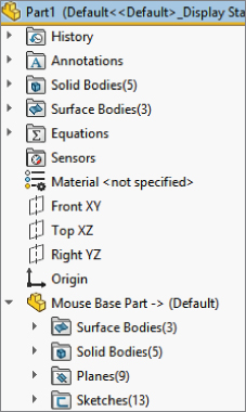
FIGURE 33.3 The FeatureManager showing items inserted with an inserted part
You cannot be selective about which bodies are pulled forward—solids or surfaces—but you can delete unwanted bodies after you have brought them all in (using Delete/Keep body). If you are trying to handle data efficiently, this may not be the best option for you. Because you must first bring forward all the bodies and then delete those you don't want, the body data is still stored inside the part. Remember that the Delete/Keep bodies is a history-based feature and doesn't actually delete; it suppresses the body and simply makes it inaccessible in the part history. If you are inserting a part with many complex bodies, you may want to use a more selective method such as Insert Into New Part or Save Bodies, each of which is described in more detail later in this chapter.
One of the advantages of using Insert Part is that you can insert the part at any point in the child part's feature history. Using configurations, you can also insert the parent part at any point along the parent's feature history. Using part history is one of the trickiest aspects of working with multiple models, whether you are working in the context of an assembly or using a master model technique.
For the inserted part, you can set configurations of the parent document in the External References dialog box, which is available through the RMB menu of the feature that is inserted into the child document FeatureManager. The External References dialog box is shown in Figure 33.4. If the overhead of bringing many bodies forward only to be deleted is an issue for you, then you can use parent part configurations to delete the bodies first; then you can select which configuration to insert by using List External References from the child document.

FIGURE 33.4 The External References dialog box
As the original inserted bodies are modified by additional features in the child document, the names change, and they are removed from the folder under the inserted part and appear only in the Body folders under the top level.
File management is a real issue with all these master model functions; in fact, it may be the biggest problem that arises with them, although you could say the same thing about overall body management. It's safe to say that you should be careful and follow file management best practice recommendations when performing name changes for documents with external references, especially if they use any of these features.
If you want to get a little practice with the Insert Part feature, follow this workflow:
- Open a new part. Call this the child part.
- Identify an existing part from which you want to make some references. Call this the parent part. Examples of the kinds of references that you might want to make between parts in an in-context assembly include matching a size or location of a feature on the parent part. To make it most interesting for experimentation, the parent part should have multiple solid or surface bodies.
- With the child part open, click Insert ➢ Part.
- In the PropertyManager that appears (refer to Figure 33.2), select the entities that you want to bring forward from the parent to the child.
- Experiment with making relations between new geometry and the inserted geometry. Use multibody techniques to manage the visibility and access to the inserted bodies.
The Insert Part feature has received lots of attention from SolidWorks developers. For this reason, Insert Part in more recent versions of SolidWorks is most resilient to changes and is the most flexible when allowing the user to make changes.
For example, if the name of the parent file changes, you can edit Insert Part to recover from that error. If the number of bodies in the parent part changes, you can edit the results in the child part to prevent more downstream errors.
Unfortunately, this feature is also inefficient for inserting parts with large numbers of bodies. You may want to choose one of the following techniques for using a single body from a part with a large number of bodies. Insert Into New Part would be a good function for this because it allows you to be more selective about which body is brought forward from the parent to the child.
Understanding the Insert Into New Part Feature
Insert Into New Part qualifies as a Pull function because it doesn't create a feature in the FeatureManager of the parent file, even though it's actually initiated from the parent rather than from the child. This function doesn't have a drop-down menu location, nor does it have a toolbar button. You can initiate it only through the RMB menu from either the FeatureManager Solid or Surface Bodies folders or from the individual bodies within the folders.
This gives Insert Into New Part both advantages and disadvantages when compared to Insert Part. One advantage is that it can selectively insert either solid or surface bodies, or even selections of both types. You can Ctrl+select multiple bodies (solid and/or surface) to bring forward only the bodies you need. However, it cannot bring forward planes or axes, or change the selection of what is brought forward after you create the feature. You also cannot use it to add a body to an existing part file; you can only use it to create new documents. This is definitely a good news/bad news situation, but with this information, you can make a more informed decision about which function to use.
When you use Insert Into New Part to place bodies into a part, the bodies are not shown in the same way that the Insert Part function shows them. In Figure 33.5, the Stock feature symbols are used rather than the Inserted Part symbol.

FIGURE 33.5 Bodies placed in a part using Insert Into New Part
Keep in mind that if this feature loses its referenced bodies, they cannot be reattached. This means that you cannot intentionally replace a body. For most users, neither situation (lost references or the need to replace bodies) should arise often, if at all, but it may still be a roadblock when implementing this function.
Using Push Functions
Push functions are initiated from the master model (parent document) and push data from the parent part out to a child part. A feature in the tree of the parent identifies the point at which the model is pushed out to the child, and the child file can be found from the parent. These options combine to give the Push functions better overall control than the Pull functions; however, there might be other factors that are more important.
The first feature in the child part is a Stock feature, which contains a reference back to the parent, so the parent can be found from the child. The features that fall into this category are Split and Save Bodies. The bidirectional identification of the source (parent) and target (child) of the feature offers a distinct advantage over the Pull functions, which don't allow you to identify the child from the parent document.
Working with the Split Feature
![]() The Split feature has three functions, two of which are plainly visible and one that's hidden. Its main function is, of course, to split a body into multiple bodies. It can also save the bodies to individual parts. The hidden function is that it can then create an assembly and reassemble the individual parts back into a complete assembly where all the parts are placed in their original relationships to one another. The Split PropertyManager is shown in Figure 33.6.
The Split feature has three functions, two of which are plainly visible and one that's hidden. Its main function is, of course, to split a body into multiple bodies. It can also save the bodies to individual parts. The hidden function is that it can then create an assembly and reassemble the individual parts back into a complete assembly where all the parts are placed in their original relationships to one another. The Split PropertyManager is shown in Figure 33.6.
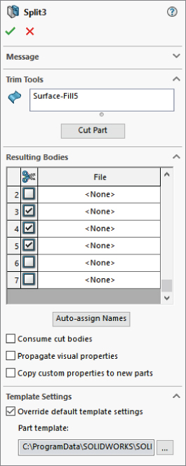
FIGURE 33.6 The Split PropertyManager
SPLITTING A BODY
The primary function of the Split feature is to split a single solid body into multiple bodies. You do this with sketches, planes, or surface bodies. The Split feature can save both the preexisting bodies and any bodies that result from the split as individual part files using the Stock feature as the initial feature in the part.
ASSIGNING NAMES AUTOMATICALLY
The ability to save solid bodies out to part files directly from the lower half of the Split PropertyManager caused some serious file management problems in earlier versions of SolidWorks. Fortunately, recent versions of SolidWorks have removed most of the bugs from this complex feature.
When you save the bodies to individual part files, SolidWorks automatically assigns names for the parts. These names take the form of <Body1>.sldprt. You can manually assign names either in the lower half of the Split PropertyManager or in callouts on the screen. You can change the names later if necessary. Features added to the parts created from the Split feature should update correctly when you rename the parts in the Split feature.
One drawback of creating parts using the Split feature is that you cannot insert the body geometry at any point in the child feature history. It goes only at the top. You cannot insert the data into an existing part; it can be put only into a new part.
CREATING AN ASSEMBLY
After you create the Split feature and save bodies to new parts, the RMB menu displays the Create Assembly option, which puts all the parts from the bodies in the original part back together in the correct positions. Parts within the assemblies that you create this way are fixed in space with the same relationship to the assembly origin that they originally had as bodies to the part origin. Although this arrangement doesn't need mates to be properly positioned, it doesn't easily allow motion. To allow motion, you must mate the parts using more traditional assembly methods.
Create Assembly is also a separate feature, found in the Insert ➢ Features menu. It uses the same icon as the Split feature. It will not allow you to put the bodies into an existing assembly, you have to create a new one. It will allow you to combine the body results from multiple Split features, to allow some efficiency.
Working with the Save Bodies Feature
To access the Save Bodies feature, you can either right-click the Bodies folder and select it from the RMB menu or choose Insert ➢ Features ➢ Save Bodies from the menu options. Save Bodies works by displaying path and filename information in the Resulting Bodies selection box of the Split PropertyManager. However, Save Bodies enables you to create an assembly right in the PropertyManager for the feature, rather than as a hidden feature with no record of the assembly name created by the feature. The PropertyManager for Save Bodies is shown in Figure 33.7.

FIGURE 33.7 The Save Bodies PropertyManager
Save Bodies is found in the Solid Bodies folder RMB menu and the lower half of the Split feature PropertyManager. You can use it to save bodies to parts if the bodies already exist. Save Bodies also has the Create Assembly functionality built right into the PropertyManager.
In both the Split and Save Bodies PropertyManagers, the Consume Cut Bodies option means that if a body is saved to a part, it is removed from the parent part. So, if you saved all the bodies to files, the parent part would be empty after the Split or Save Bodies feature in the FeatureManager.
Tutorial: Working with Master Model Techniques
Some of the concepts presented in this chapter may not make much sense until you apply them to a specific situation. The goal of this tutorial is to demonstrate the strengths and weaknesses of the various functions, as well as to give you some practical experience with the file management issues you'll encounter. In the following tutorials, you will use each of the four tools with the mouse multibody part to become familiar with their different functions.
To work with the Insert Part function, follow these steps:
- Make sure you have access to the files from the download materials for Chapter 33. Create a new part, and insert the part named
Mouse Base Part.sldprt. You can access Insert Part by choosing Insert ➢ Part from the menu options. After you issue the command, SolidWorks will attach the part to your cursor and prompt you to specify a location for the inserted part in the PropertyManager. Drop the part at the origin of the child part, or simply click the green checkmark icon to accept the part. There is no need to use the Move dialog box; if it appears, deselect the option that enables it. For this part, don't transfer any of the optional items, only the solid bodies. - After the feature is accepted and appears in the feature tree, right-click it and select List External Refs from the menu. The External References dialog box will appear with the list of configurations displayed, as shown in Figure 33.8.

FIGURE 33.8 The External References dialog box
- Select the Wheel configuration from the list.
- Save and name the part file in such a way that it has the name of the technique used to create it (Insert Part) and the name of the body that it represents (such as Wheel).
- Repeat steps 1 through 4 for each of the five bodies in the master model.
- If the mouse master model (
Mouse Base Part.sldprt) is open, close it. In any of the child parts, the inserted-part feature shown in the tree should display the Out Of Context symbol (−> ?). Right-click the inserted-part feature and select Edit In Context; this will open the master model.Notice that from the master model, you have no way of knowing where the child parts are or even if any child parts exist. Notice also that there's no easy way to create an assembly.
- Create a new assembly document.
- Drop all the individually created parts into the assembly by selecting them in Windows Explorer and dragging them onto the assembly origin. This is probably the easiest way to create an assembly using the Insert Part feature.
- Save and close all the parts and assemblies.
To work with the Insert Into New Part function, follow these steps:
- For this feature, start from the master model; open the part Mouse
Base Part.sldprt. Make sure the part is set to the Default configuration. If it's set to a different configuration, inserting bodies will require an extra step of assigning which part configuration to use in the assembly. - Expand the Solid Bodies folder in the FeatureManager. Right-click the first body in the list (Wheel) and select Insert Into New Part from the menu.
- When prompted, name the new part using the same convention used in the previous tutorial, which was to use the name of the technique (Insert Into New Part) and the name of the body. In this part, leave the configuration setting in the External References dialog box to the Default configuration.
- Repeat steps 1 through 3 for each of the bodies.
- Right-click the Stock feature in the tree and select Edit In Context. SolidWorks will open the master model part.
- Create a new assembly document and use the same technique from the previous tutorial to put all the parts in the assembly located from the origin. Again, no automated assembly creation tool exists for this method.
- Save all the documents and close them.
To work with the Split function, follow these steps:
- This time, start from a copy of the master model part. The Split feature makes additions to the model, and because you have already created assemblies based on the original, you should create any additional features using a copy of the part rather than the original. Copy it using the Copy and Paste feature in Windows Explorer and rename the copy as Split Tutorial.
- With the newly copied and renamed document open, initiate the Split feature by choosing Insert ➢ Features ➢ Split.
- Because the bodies already exist, there's no need for the Trim tools or Cut Part functions in the Split feature, only for the resulting bodies. To save the bodies to individual files, you must give each one a unique name. You can click the Auto-Assign Names button to automatically name them with the existing names of the bodies. It might be difficult to discern where the callout flags are pointing. After all the names are satisfactory, click OK to accept the feature.
- To automatically create an assembly with all the components located in the proper location, right-click the Split feature in the Master Model FeatureManager and select Create Assembly. Multiple Split features can be included in this command if bodies have been created by multiple Split features. Click the Browse button to locate and name the new assembly. Click OK when you are finished. Completing this step opens the assembly that you just named and located. When you create the assembly, the parts appear but may not be displayed in the FeatureManager until you have saved and reopened the assembly file. You should still have access to the data through the RMB menu from the graphics window.
- Right-click one of the parts in the assembly to open it. Notice that a Stock feature is used in the tree, so you can access the parent part and change the parent part configuration used in the current part. Right-click the Stock feature and select Edit In Context.
- With the master model open, right-click the Split feature and select Edit Feature. From here, you can see where each of the child parts is located.
- If you rename any of the documents, you should do this by using either SolidWorks Explorer or the Save As command with the other documents open as well. If you want to rename the parent part (master model), make sure that all the child parts are open as well. (You can easily do this by opening the assembly; although the assembly was created from the master model, there's no direct link between the Split feature and the assembly.)
- Save and close all the files before proceeding.
To work with the Save Bodies function, follow these steps:
- As before, create a copy of the original master model part, and rename the copy Save Bodies Tutorial.
- Open the renamed copy and right-click the Solid Bodies folder. Select Save Bodies from the menu. (Save Bodies has its own icon, which looks like the Split icon and is used to denote the placeholder feature in the FeatureManager.)
- Use the Save Bodies PropertyManager to save the solid bodies to separate files. (This interface is nearly identical to the lower section of the Split PropertyManager.) The major addition in the Save Bodies dialog box is that the Create Assembly function is directly within the PropertyManager. The primary benefit of this addition is that it retains the name and path of the assembly in this interface so you can look it up later if necessary.
- Open the reconstructed assembly. Right-click one of the parts and select Open Part to open it in its own window. Notice that the Stock feature has again been used to push a single body into the part.
- Right-click the Stock feature and select Edit In Context, which will take you back to the master model.
- Save and close all the files.
The Bottom Line
Each of the four functions covered in this chapter has strengths and weaknesses. The Insert Part feature is probably the most flexible of them, mainly because of the additional items you can bring forward from the parent document, and the fact that it can handle both solid and surface bodies. The Split feature also has unique strengths because of its ability to split bodies, save multiple bodies to files, and reassemble the parts as an assembly.
If you are working with surface bodies, you must use Insert Part or Insert Into New Part. Another important strength can be found in the Save Bodies feature, which makes the child accessible from the parent and identifies the assembly in the parent.
- Master It Leading up to master model techniques, you need to be proficient with body management. Master model is really just moving the body conversation to external files.
- Name the four Master Model tools.
- Name three body management tools.
- Master It Follow these steps:
- Open a new part, draw a centered rectangle centered on the origin, and extrude it mid-plane to make a block.
- Use the Split command and the three default planes to split the part into eight bodies. (Click the scissors to automatically select all the bodies for saving to parts.)
- Use Auto-Assign Names within the Split command to make parts for each body.
- Use the Create Assembly command (Insert ➢ Features) to create an assembly from the bodies created by the Split Command.
- Assign different appearance properties to each part in the assembly.
- Open the List External References for one of the bodies and locate the path to the original part.
- Use the Lock All button to lock references for this body. Notice that only the references for this body are locked. The rest of the external references are still functional.
- The locked external reference symbol −> * shows up on the locked part, but the rest of the parts still use the active external reference symbol −> . Check this by editing the Stock feature for both locked and unlocked parts.
- Master It Go back to the master model (the original part where the block was created) and follow these steps:
- Close all parts and assemblies other than the original master model.
- Using the Save As Copy and Continue option, save the master model with a new name. Then close the master model. Everything should be closed at this point.
- Open the new master model.
- Roll back before the Split feature and add fillets to all the corners of the part, and then roll back down after the Split feature. (The Split feature fails.)
- Edit the Split feature, recut the part with the three planes, and reassign names to all the bodies. Notice that SolidWorks avoids the previously created filenames. Make sure the Propagate Visual Properties option is selected. Exit the feature.
- Assign the colors in the part to the bodies this time, and the colors will propagate to the parts.
- Execute the Create Assembly step again, making a new assembly with the new master model.
- Use Isolate to edit each body in the new assembly and add a Shell feature that removes the inside faces. Do this for at least three of the parts.
- Change the size of the second master model, save it, and then switch to the assembly, which will update.