
Chapter 31
Modeling Multibodies
SolidWorks allows multiple solid bodies within a single part at the same time. SolidWorks defines a solid body as a single contiguous volume. So, if you have two blocks in the same part that don't touch one another, those blocks are separate bodies. Separate bodies can intersect, and you can have copies of bodies that are exactly on top of one another. Surfaces are also bodies. While solid features by default try to form a single body if possible, surface bodies by default make separate bodies.
There are many uses for this type of functionality. At the same time, there are many ways to abuse this functionality and fall into traps. This chapter aims to help you take advantage of the benefits of multiple bodies while avoiding some of the potential traps.
You might work with SolidWorks in such a way that you would never need to use multiple bodies inside a single part, ever. Almost everything that average users normally do can be done with a single solid body per part and without any knowledge of multibody functionality whatsoever.
However, to access some more powerful functionality and options that offer more flexibility, multibody modeling is necessary. In fact, if you want to move on to surface modeling, multibody knowledge is mandatory because multibody is the default in surface modeling.
Multibody modeling is the gateway from the basic solid modeling mainly described in this book up until now into the more advanced functionality that follows. The gateway can lead in two directions: It can lead to more power, more flexibility, more options, and more advanced functionality, or it can lead to sloppy, bad habits and nasty traps. This chapter will help you tell the difference and avoid the pitfalls.
Using Powerful Tools Effectively
The SolidWorks software is so filled with powerful functionality that you'll find many ways to create any given piece of geometry. In SolidWorks, the geometry itself isn't the only measure of success. What's also important is how you arrived at that geometry. This isn't because some SolidWorks style police pass judgment on your technique, like a panel of judges rating an Olympic diver, but rather because your models will be passed on to other people who will need to understand how you got your results, and because your model must be able to react predictably to changes. It's not always easy to remember how you executed a particular model six months and 100 models ago. Other users may have to edit your work, and when errors appear (and they will appear), you will have to be able to navigate the design intent without destroying the relationships in the FeatureManager or completely rebuilding it. This is the reason for trying to standardize best practice issues, particularly with advanced functionality and in larger organizations where users with a wide range of abilities may work with the data.
Comparing Multibody Modeling with Assembly Modeling
Multibody modeling is one topic that bridges the worlds of part and assembly modeling. If you're a new user, you may not understand what the big deal is; after all, you just make bodies within a part, right? By the end of this chapter, you should be able to recognize that the issue is more complicated than that. If you're an experienced user, you may have already run into some problems with figuring out where to draw the line between multibody parts and assemblies. This chapter also offers you some answers.
Multibody modeling is not assembly modeling. Often, when new users are introduced to the capabilities of multibody modeling, the first thought that comes to mind is, “This is far easier than making assemblies.” However, multibody modeling shouldn't be treated as a replacement for assembly modeling. There are practical reasons for the distinction.
Several assembly-type functions are missing or more difficult to obtain from multibodies. They include the following:
- Dynamic assembly motion
- Configs for separate parts and the Delete Body command
- Bounding box for separate parts and cut-list items
- Center-of-gravity calculations for individual parts
- Custom property information for individual parts and cut-list properties
- Mass property calculations for individual parts with the ability to save the results in a cut-list property or sensor
- Multibodies do not allow you to segment the rebuilds like assemblies and parts.
- Multibody troubleshooting of feature failures is far more difficult.
- Reusing commonly used parts (library parts)
I believe that the distinction between multibody and assembly modeling techniques should be kept as clear as possible. Simply because a technique appears easier at first does not make it better. Above all, remember that modeling multibody parts puts all the data for all the bodies in a single part file, in a single FeatureManager; there's no easy way to separate the parametric features into individual parts later, regardless of how complex the part becomes.
You may find parallels between making multibody parts and making virtual components (parts that are saved within an assembly file). Although both these techniques offer shortcuts or make some basic tasks easier, good reasons exist for being mindful of the “one part, one file” mentality, including the following:
- Segmenting rebuild times (the ability to rebuild one part instead of several)
- Segmenting large data sets (being able to work on one part at a time)
- Switching out parts
- Using multiple instances of parts
- Reusing parts
- Bills of Materials (BOMs)
- Cut lists in parts
Further, creating drawings of individual bodies of a multibody part is more difficult than creating drawings of individual parts; it can be done, but it's more difficult. Also, editing the features of individual bodies isn't as easy as if the individual body were an individual part. When you create several bodies in a single part, you constantly have to carry the feature and design intent overhead of all the features used to create all the bodies to edit any individual body. As an alternative, you can use the editing features at the end of the tree.
Using Multibody Techniques Appropriately
You may hear people recommend that at the end of the FeatureManager, only a single solid body should remain, with the rest of the bodies either consumed or deleted. On the other extreme, for some people, anything they can create is allowable. I recommend that if you decide to use multibodies, you should at least be able to articulate why you have chosen to do so in a way that doesn't sound like you're making excuses for careless work. Ultimately, you and your peers will be the ones to judge.
Multibody modeling is one of the areas that will induce a lot of arguments about best practices. As an example of a technique that is questionable by best practice standards but can add some capabilities to some things you do with multibody models, you can declare a multibody model as a weldment and gain certain tools such as cut lists. But if you're doing this for a plastic part, some other users may find it confusing. In the end, it is my opinion that you are best served using the available tools as they were meant to be used. The more people who are going to see your models, the more orthodox you should be with best practice rules, especially if some of the other users working with your data are less advanced.
Appropriate uses for multibody modeling include (but are not limited to) the following:
- As an intermediate step on the way to a single-body solid
- As multiple or inserted bodies for reference (reference bodies may be deleted at the bottom of the FeatureManager)
- As over-molded parts
- As parts that need to be assembled into a single, smooth shape, such as a computer mouse or an automobile body where the shape is impossible (or at least far more difficult) if done in-context
- When the end shape of the finished product is known, but the separation occurs between parts due to manufacturing methods, and materials have not been decided yet (In this case, multibody techniques can save lots of time compared to modeling an assembly.)
- As inseparable subassemblies (such as captive fasteners)
- When SolidWorks weldments result in a multibody part
- When features require tool bodies, such as the Indent feature
- When patterns are better as body patterns than as feature patterns
- When the Mold tools result in a single multibody part representing the plastic part and the major mold components
- Calculating volume of a void (cavity or hollow area)
- When the volume of a cavity (in a part or an assembly) needs to be computed
If you are administering a SolidWorks installation of multiple users, then you may be looking for a “bright line” test to clearly define for users which types of multibody modeling are allowable and which are not. So many possibilities exist that it's difficult to say definitively what really should not be done, but here's a short list that you can modify for your needs:
- Don't use multibody modeling simply to avoid making an assembly.
- Don't leave a part in a multibody state that should be joined together into a single body.
- Hiding a body is sometimes appropriate, and deleting a body is sometimes appropriate—understand the difference.
Okay, the lecture is over. The message that you should take from all this is not to use multibody techniques just because you can; use them when you have a solid reason to do so. This is the criterion that I use for my own modeling, what I would like to see in models that I inherit from other SolidWorks users, and a philosophy that will serve you well if you're conscientious about it.
Multibody modeling is powerful, and for complex parts, it can even increase rebuild speed compared with single-body modeling or assembly modeling. You can develop and use many powerful techniques based on multibodies, but as I mentioned earlier, sometimes you pay a price for the shortcut.
Understanding Multibody Techniques
Multibody techniques cover a wide range of functionality, and as soon as someone creates a list of what you can do with them, someone else comes up with a new technique. Still, here's a short list of techniques where multibody functionality makes things either easier or simply possible:
- Complex shapes across multiple parts
- Tool bodies and Boolean operations
- Local operations
- Patterning
- Simplifying very complex parts
- As a bridge between solids
- Undetermined manufacturing methods
- Manipulating imported geometry
In the remainder of this chapter, I will illustrate each technique using an example model and discuss the positives and negatives. As you get deeper into SolidWorks, you'll find that the more complex functions tend to come at a price. A given feature might be the only way to accomplish a particular task, but it rebuilds slowly, might work only in special conditions, might crash from time to time, or might not make sense to other users if they have to edit it.
Using Simple Methods to Create Multiple Bodies
The simplest way to create multiple bodies may also help you understand what multibody models are and how they are used. SolidWorks automatically counts the bodies in the Solid Bodies folder. For reference, the Solid and Surface Body folders are shown in Figure 31.3, along with the Display pane to aid in visualization (Color, Transparency, Hide/Show, and Display mode).
EXTRUDING MULTIPLE LOOPS
If you create two rectangles or other loops in a sketch such that the rectangles don't touch or overlap, and then extrude those rectangles, you will create a multibody part. You could also do the same with two separate features. They could be any solid features, as long as they create two separate volumes. This is demonstrated in Figure 31.1.

FIGURE 31.1 Creating multiple bodies with a single extrusion
MAKING CUTS
You can also take an existing single body and cut it such that a solid chunk remains. Making a cut that severs a single solid into multiple pieces (more than two) is also possible. Sometimes you have to watch out for this, because it may not be your intention to cut off a small sliver of material, as you can wind up with multiple bodies by mistake. It's a good idea to keep an eye on the Solid Bodies folder to make sure the count doesn't change unexpectedly. However, when the part only has a single solid body, SolidWorks by default hides the Solid Body folder.
USING THE MERGE OPTION
Another easy way to create multiple bodies when you have an existing model is to start a feature connected to the rest of the model, in the normal way, but then turn off the Merge Result option. As illustrated in Figure 31.2, if you have the Merge Result option turned on, the two existing bodies and the new feature will merge into a single body. If the Merge Result option is off, the result will be three separate bodies. Solid features have the Merge Result option turned on by default. This Merge Result option is also available in revolves, lofts, sweeps, and other features that create new solid geometry.
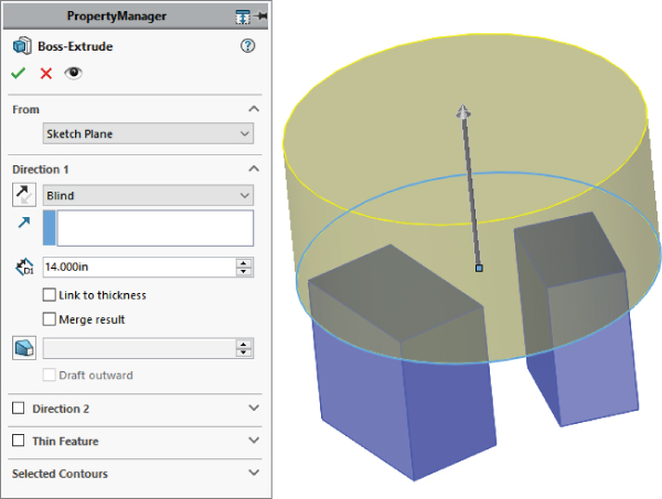
FIGURE 31.2 Using the Merge Result option in the Extrude PropertyManager
SHARING BODIES
Bodies can be imported from other SolidWorks models or through neutral file types such as Parasolid, STEP, and IGES. SolidWorks has several tools that do this, and they all function similarly with some subtle differences. These six tools are listed here:
- Import/Export
- Insert Part
- Insert into New Part
- Split
- Save Bodies
- Delete/Keep Bodies
These tools have overlapping functionality and are described in more detail in Chapter 33, “Employing Master Model Techniques.” For now, it is enough to know that these functions all enable you to manage bodies in SolidWorks.
Creating Complex Shapes Across Bodies
When creating a part such as a computer mouse, you encounter complex shapes that span several individual parts. It makes the most sense to model the entire shape as a single part and then to break it up into separate bodies, making parts from the bodies, adding detail to individual piece parts, and then bringing the parts back together as an assembly.
A part that uses this technique is shown in Figure 31.3. This uses the Move/Copy Bodies feature to move bodies within the part to simulate the explode, although an exploded view can also be used in multibody parts. This function remains in the part as a history-based feature in the FeatureManager and is much more labor-intensive to create than an assembly exploded view because each body is moved by a separate feature.

FIGURE 31.3 A multibody part with a complex shape across bodies
The part shown in Figure 31.1 is not complete, but the starting point for each part has been formed. The part is named Chapter 31 – multibody mouse.sldprt and is located in the materials available for download. You may find it interesting to open the part to see how it has been modeled.
From here, each body is saved to individual parts to complete the detailing, and then the parts are brought back together to create an assembly. The separate bodies in this case were created using the Split feature, which enables you to use surfaces, sketches, or planes to split a single body into multiple bodies. This is described in more detail later in this chapter.
The entire process for creating a finished assembly of finished parts is detailed in Figure 31.4. This flow chart shows conceptually how the overall shape created as a single part has moved from a single part/single body to a single part/multiple body to individual parts to an assembly of individual parts. This process is sometimes called the Master Model workflow because all of the individual parts are driven by a single master model.
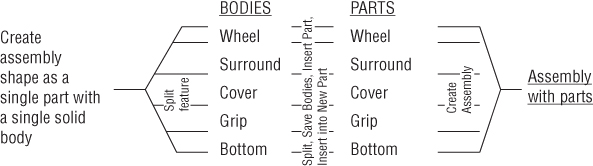
FIGURE 31.4 A Master Model workflow
In Figure 31.5, the image to the left depicts how this part was modeled. The first step was to create the shape as a single body within the part. As shown in the FeatureManager, this is all contained inside the Overall Shape Features folder. This folder is presented here as a black box because surface features were used to create the part. It really doesn't matter at this point how the part was created, and these features are not discussed until Chapter 32, “Working with Surfaces.”

FIGURE 31.5 Splitting the part into bodies
The image to the right in Figure 31.5 shows transparent surface bodies that were used to split the model into separate bodies using the Split features shown in the tree. Using this technique, you can create the overall shape as a single piece and then split it into separate parts. You also can apply this technique in the context of an assembly, but this method is far more direct.
To go from the multibody part created here to a set of separate parts uses a Master Model function, which is described in more detail in Chapter 33, “Employing Master Model Techniques.”
Using Tool Bodies and Boolean Operations
Some features require multiple bodies within a part, such as the Indent and Combine features, among others. Using one body to create a shape in another is a common use for bodies within a part. The body with the finished geometry is called the target, and the body used to create or edit the shape is called the tool.
USING THE INDENT FEATURE
![]() The Indent feature is covered briefly in Chapter 8, “Selecting Secondary Features,” before multibodies are introduced, so it's fitting that I revisit it here so you can better understand the multibody aspect of its use. The Indent feature indents the target body with the tool body. It can also use another part in the context of an assembly as the tool. The indentation can exactly fit the form of the tool, or there can be a gap around the tool. You can also control the thickness of the material around the indent. A further option is to simply cut the target with the tool instead of indenting.
The Indent feature is covered briefly in Chapter 8, “Selecting Secondary Features,” before multibodies are introduced, so it's fitting that I revisit it here so you can better understand the multibody aspect of its use. The Indent feature indents the target body with the tool body. It can also use another part in the context of an assembly as the tool. The indentation can exactly fit the form of the tool, or there can be a gap around the tool. You can also control the thickness of the material around the indent. A further option is to simply cut the target with the tool instead of indenting.
Figure 31.6 shows the target part as transparent and the tool as opaque, before and after the Indent feature has been applied. The Indent PropertyManager is also shown.

FIGURE 31.6 The Indent feature using a tool body
The Indent feature can be problematic if it breaks into multiple areas as it does in this part, due to the ribbing on the underside of the target body. Notice that in the PropertyManager in Figure 31.6, two selections were made in the Tool Body Region selection box. The tool body is selected on either side of the rib that bisects the tool. This concept is not very intuitive, and you may have to play with the part and the options to understand what it's doing.
The Keep Selections and Remove Selections options are equally unintuitive, but they determine which side of the target body is indented. For example, if the part of the tool body that's outside of the target body (the flat side) is selected instead of the two inside regions, the resulting part looks as it does in Figure 31.7, where the tool body has been hidden. You can achieve the same result by toggling the Keep Selections and Remove Selections options. These options exist because sometimes it's difficult or impossible to select the correct areas of a body that's embedded in another body.
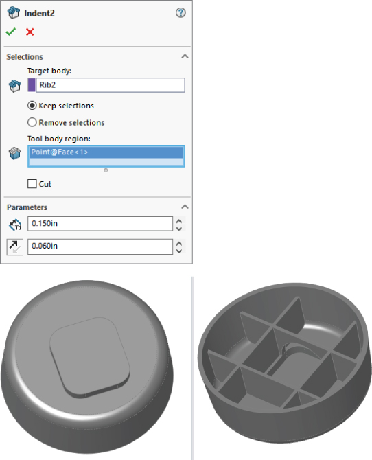
FIGURE 31.7 Using the Keep and Remove Selections options
USING THE MOVE/COPY BODIES AND COMBINE FEATURES
![]() The Move/Copy Bodies and Combine features can be demonstrated using the same part. The tool body that was used in the previous example to indent the main body is moved and then added to the main body in this example.
The Move/Copy Bodies and Combine features can be demonstrated using the same part. The tool body that was used in the previous example to indent the main body is moved and then added to the main body in this example.
![]() Figure 31.8 shows the starting and ending points of the process, as well as the PropertyManagers of the two features used to get from one point to the other. Keep in mind that both the Move/Copy Bodies and the Combine features are history-based features listed in the FeatureManager.
Figure 31.8 shows the starting and ending points of the process, as well as the PropertyManagers of the two features used to get from one point to the other. Keep in mind that both the Move/Copy Bodies and the Combine features are history-based features listed in the FeatureManager.

FIGURE 31.8 Using the Move/Copy Bodies and Combine features
In this case, the Move or Copy Bodies feature uses distances and angles with the orange Triad. You can also use mates to move or locate the body. These mates enable you to locate bodies in a way that’s similar to the way they are used in assemblies.
In the Combine PropertyManager, you'll notice that common Boolean operations—such as union (add), difference (subtract), and intersection (common)—are available through this interface.
You can use an interesting technique in this part. The features creating the smaller tool body and the Move/Copy Bodies and Combine features can be put together into a folder, and the folder itself can be reordered before the Shell feature. This means that the combined body is also shelled out, and the rib goes down inside of it. This produces an odd error message and unexpectedly places several features into the folder, but it does work.
You may want to open this part in SolidWorks to see exactly how all this was done instead of relying on the figure illustrations. The part used for Figure 31.9 is in the download material and is named Chapter 31 – rib trick.sldprt.

FIGURE 31.9 Reordering features
Using Local Operations
If you have ever had a modeling situation where you needed to shell out a portion of a part but not the entire part, or you had a fillet that would work only if certain geometry were not there, then you may have been able to benefit from multibody techniques to accomplish these tasks.
USING THE FLEX FEATURE
![]() The part shown in Figure 31.10 first appeared in Chapter 8, “Selecting Secondary Features,” where I demonstrated the Flex feature. This is a rubber plug for an electronic device. In order to make one side of the part flex without flexing the other side, multiple bodies were used. The part was split into two bodies using the Split feature and a plane. One side of the part was then twisted, and the two bodies were recombined. The Features folder contains the features that were used to build the original part geometry, which could just as easily have been either native or imported.
The part shown in Figure 31.10 first appeared in Chapter 8, “Selecting Secondary Features,” where I demonstrated the Flex feature. This is a rubber plug for an electronic device. In order to make one side of the part flex without flexing the other side, multiple bodies were used. The part was split into two bodies using the Split feature and a plane. One side of the part was then twisted, and the two bodies were recombined. The Features folder contains the features that were used to build the original part geometry, which could just as easily have been either native or imported.

FIGURE 31.10 Splitting a part to perform a local operation
USING THE SHELL FEATURE
![]() The Shell feature hollows out one solid body at a time, removing selected faces. If there are multiple solid bodies, you must select one to be shelled. You can select a body without selecting a face by using the small Solid Body selection box under the larger Faces To Remove selection box in the PropertyManager. If you don't select any faces to be removed, then the body is hollowed out with no external indication that the part is hollow unless you view it in section view, transparency view, or wireframe view. Single or multiple faces can be removed. This feature works by offsetting the faces of the outside of the model, and the feature may fail if this causes problems with the internal geometry.
The Shell feature hollows out one solid body at a time, removing selected faces. If there are multiple solid bodies, you must select one to be shelled. You can select a body without selecting a face by using the small Solid Body selection box under the larger Faces To Remove selection box in the PropertyManager. If you don't select any faces to be removed, then the body is hollowed out with no external indication that the part is hollow unless you view it in section view, transparency view, or wireframe view. Single or multiple faces can be removed. This feature works by offsetting the faces of the outside of the model, and the feature may fail if this causes problems with the internal geometry.
The Multi-Thickness Shell option enables you to select faces that will have a different thickness from the overall shell thickness. This is one method that you can sometimes use to restrict the scope of the Shell feature to a certain area of a body, Multi-thickness shell is somewhat limited in that faces with different thicknesses will not shell if they are tangent or nearly tangent to one another.
Because the Shell feature works on only one body at a time, splitting a part into multiple bodies can be an effective way to limit the scope of the feature. The part shown in Figure 31.11 has been split in half, and one-half has been made transparent for visualization purposes; as a result, you can see that the part is shelled on the bottom on one end and on the top on the other end. The Shell feature has no option for doing this with existing geometry. The only ways that you can do this are either through feature order or by using multibodies. You can find the part shown in Figure 31.9 in the download material with the name Chapter 31 – LocalOps Shell.sldprt.

FIGURE 31.11 Shelling locally
To shell the part this way with feature order, you create one block and shell it, and then create the other block and shell that. In order for this technique to work, the second shell must be as big as, or bigger than, the first shell. If it's smaller, then it will (or may) hollow out areas that aren't intended to be hollow.
To shell the part with multibodies, you can use two methods. One method is to build the first block and then build the second block but turn off the Merge option. This creates bodies that are side by side. You then shell one block on the bottom and the other on the top. To avoid a double-thickness wall between them, the end face can be removed along with either the top or bottom face. If you edit the part, you may notice that one of the Shell features has two faces removed.
The second method is to build a single block and split it using a sketch line, a plane, or a surface, and then proceed in the same way as the first method.
Patterning
Patterns of bodies are fast, powerful, and commonly used alternatives to patterning features. Chapter 9, “Patterning and Mirroring,” discusses feature patterns and mirroring, and it examines, at least in part, how different types of patterns affect model rebuild speeds. When appropriate, patterning bodies can also be a big rebuild timesaver. When patterning a body, none of the parametrics or intelligence is patterned with it, but you must pattern the entire body. Another odd thing about patterning bodies in SolidWorks is that there's no option to merge the bodies either to one another or to a main body. This requires an extra step that involves adding a Combine feature. Mirroring is the same, except that it has an option to merge bodies, but it only merges the original body to the mirrored body. It doesn't merge either the original or the mirrored body to a central main body.
In this example, an imported part has a “feature” that needs to be reused around the part. The technique used here is to split away the feature as a separate body and then pattern the body around the part and join it all back together. This function can be used with native geometry as well as imported. This process is shown in Figure 31.12. This function uses a simple planar surface. A plane could have been used to split off the body to be patterned, but the plane would have also split off a part of the globe at the top, so a planar surface (which can be limited in extent where a plane cannot) was used.

FIGURE 31.12 Splitting away a body and patterning it
The image on the left in Figure 31.12 is the raw imported part. The middle image shows a planar surface created on the face of the part, where the planar surface has been used with the Split feature to cut the leg off the part. The image on the right shows the split leg patterned around an axis that was created from the intersection of two planes.
If you want to practice with this part, it's in the download material for Chapter 31; the imported Parasolid file is named Chapter 31 – Pattern import.x_t.
Simplifying Very Complex Parts
Sometimes very complex parts work better when they're built in sections as separate parts than when they are built as a single feature tree. Segmenting the rebuild times for parts with hundreds of features enables you to manage how much of the tree you are willing to rebuild at one time. The example used to demonstrate this technique is a large plastic part built entirely from ribs, and making use of literally hundreds of solid bodies, and is shown in Figure 31.13.

FIGURE 31.13 A complex model created as separate parts and brought together as bodies in a single part
The rebuild time for a model like this can easily reach several minutes, and the feature count can be in the hundreds, or in this case, well over one thousand. To minimize the rebuild time, a different workflow was established for this part. First, the major inside and outside faces were created with surfaces. Next, the surfaces were saved into several other parts. Each of these parts represents a portion of the mold. Enough information exists in the master model to align the features in each part.
The ribs on this part were created by making a single extrusion (the Rib feature couldn't be used because there was no geometry to serve as a boundary for the ribs), and then the extrusion was patterned and the pattern was mirrored. After all the ribs were created, they had to be shaped, so the surfaces from the master model were used to cut the ribs to shape.
The ribs couldn't be extruded with a draft or with fillets, because the outer and inner surfaces were nonplanar. The draft had to be built as a Parting Line draft for the same reason, and the fillets had to be applied after the draft. Further, draft and fillets can only be applied to a single body at a time; as a result, a separate Draft feature and a separate Fillet feature had to be applied to each body, and each rib was a separate body. After the draft and fillets were applied, the bodies were joined into a single body.
I recognize that this description of how I made the part is a lot to comprehend. The point is not to show in detail how the parts were built, but to demonstrate how you can get to a part with 1,200 features or more. It's precisely on parts with this level of complexity that you need to think about modeling the part in this modular fashion—build each part separately and bring each separate section of the part together as individual bodies.
Figure 31.13 shows two of the separate pull direction parts being separated from one another in the same way that the mouse part was shown exploded in the previous example. Here the frame is also modeled as a separate part, again because it wasn't so intimately related to the other parts and was easily separated out.
After this was completed for each direction, the separate parts were put together as bodies into a single part and again joined together using the Combine feature. Having all those features in separate parts allows you to segment the rebuild time. This is the opposite of building all the parts of an assembly in a single part, where you are simply compounding your rebuild time.
This is probably a technique that you won't use very often, but when you do, it can save you lots of rebuild time. I use it whenever I have a model that takes more than 20 to 30 seconds to rebuild and I know that I'm going to be doing lots of work on it; it must also lend itself to segmenting in the way that this one did, with easily definable areas.
Bridging Between Solids
Often when modeling, you “build what you know” and “fill in as you go.” An example of this would be modeling a duct between end connections that are well defined. The duct in between is defined only by the ends, which must exist first. Another example is a connecting rod where you know the diameter of each end and the distance between the ends, and the connection between them is of secondary importance.
Figure 31.14 shows a connecting rod made in this way. In this case, the bearing seat at one end was created, and the other end was created by copying the body of the first one. From there, the link between the bearing seats was created, which joined the separate bodies together into a single solid body.

FIGURE 31.14 Connecting disjoint bodies
This part contains some interesting features. First is the Thin Feature extrude that's used to make the first bearing seat, which is combined with a Mid plane extrude to make it symmetrical at the same time. Then comes the Move/Copy Bodies feature, which copies the body in the same way that the feature in previous examples has moved bodies. Next is the use of the Extrude From option, which extrudes from a face, and then the use of the end condition Up To Next, which ends the feature neatly. The part also incorporates fillets that use faces and features to form the selection.
If you aren't familiar with these options, I recommend that you open the part from the download materials and look at it. It's a simple part that takes advantage of nice but simple productivity-enhancing options that have been available for some time in the SolidWorks software. The part filename is Chapter 31 – Bridge.sldprt.
By default, Solid features have the Merge option selected, and they automatically combine with any bodies that they touch. At the same time, they don't display errors if the Merge option is selected but the new body doesn't touch any existing bodies.
Modeling for Undetermined Manufacturing Methods
Sometimes, you must start a design before you know exactly how the product will be manufactured. This is an example of where the geometry of the finished product exists first and is then broken up into manufacturable parts. The initial model, shown in the image at the top in Figure 31.15, is created as a single part as a result of input from marketing, but when it comes time for manufacturing input, the part count and processes keep changing. Where the parts break from one another keeps changing as well. When that kind of change is happening, having the parts created as individual parts is a big liability because it's difficult to change. Changing which bodies are merged together is much easier.
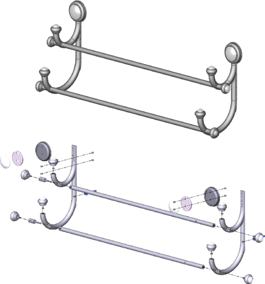
FIGURE 31.15 A towel rack, modeled as a single part and broken into individual parts in an assembly
It's worth mentioning two potential difficulties that you may run into with methods like this. The first is that if you have people making drawings from parts that have been derived from bodies in a single part, then they are forced into the Reference Dimension scheme of dimensioning parts because the feature dimensions don't survive being moved from the multibody part. This may or may not be an issue, depending on how the people doing the drawings are accustomed to working.
The second potential issue is what you do in situations where there are multiple instances of a part that has been modeled this way. Notice in the towel rack in Figure 31.15 that several finials, spacers, rails, and other parts are duplicated. Multibody techniques don't offer a way of dealing with this, so it requires some manual assembly modeling. You can make the assembly directly from the multibody part, but if you need make multiple instances of particular parts, you need to do this manually rather than automatically.
Applying the Feature Scope to Bodies
The Feature Scope is a panel in any feature that creates solid bodies, but it only appears when there are multiple bodies in the part. It isn't the same as the Feature Scope used for assembly features, but it functions in a similar way. In assemblies, the Feature Scope identifies which parts are affected by the current assembly feature. In parts, it applies only to bodies and can be used for features that add material as well as features that remove material (assembly features can only remove material).
The Feature Scope is a way to make the Merge Result option more selective. The Merge Result option by default doesn't discriminate; it causes the feature to merge with any other solid body that it touches. However, the Feature Scope enables the user to select which bodies to merge with or otherwise affect. Feature Scope also applies to additional feature types such as cuts. The Feature Scope becomes available in the PropertyManager whenever the part has multiple bodies and an eligible feature is used. The Feature Scope panel is shown in Figure 31.14.
The default setting for the Feature Scope is to use the Selected Bodies option with the Auto-Select option. The All Bodies option is essentially the same as using the Merge Result option. When the Selected Bodies option is selected and Auto-Select is unselected, you must select bodies for the current feature to affect them. New bodies that are added to the model are not automatically added to the list; you need to manually edit the feature and add additional bodies to the list as appropriate.
USING THE RIB FEATURE
![]() The Rib feature used to be hypersensitive to changes to the number of bodies. When the number of bodies changed, whether more or fewer bodies, any Rib features would fail. That bug has been fixed in recent versions; however, be aware that if you are using older versions of SolidWorks, reordering or rolling back to either add or remove bodies will cause the selection of which body to effect will fail.
The Rib feature used to be hypersensitive to changes to the number of bodies. When the number of bodies changed, whether more or fewer bodies, any Rib features would fail. That bug has been fixed in recent versions; however, be aware that if you are using older versions of SolidWorks, reordering or rolling back to either add or remove bodies will cause the selection of which body to effect will fail.
USING THE DELETE/KEEP BODIES FEATURE
![]() Prior to the 2015 version of SolidWorks, the Delete/Keep Bodies feature used to be called simply Delete Bodies. Depending on how you toggle the Delete or Keep options, the feature will keep the selected bodies and delete the rest, or it will delete the selected bodies and keep the rest.
Prior to the 2015 version of SolidWorks, the Delete/Keep Bodies feature used to be called simply Delete Bodies. Depending on how you toggle the Delete or Keep options, the feature will keep the selected bodies and delete the rest, or it will delete the selected bodies and keep the rest.
![]()
![]() Depending on how the feature is functioning, as delete or keep, the icon in the FeatureManager will change. When it works as Delete Bodies, the block will have an X in the lower-right corner. When it is functioning as Keep Bodies, it will have a check mark. The PropertyManager for Delete/Keep Bodies is shown in Figure 31.16.
Depending on how the feature is functioning, as delete or keep, the icon in the FeatureManager will change. When it works as Delete Bodies, the block will have an X in the lower-right corner. When it is functioning as Keep Bodies, it will have a check mark. The PropertyManager for Delete/Keep Bodies is shown in Figure 31.16.
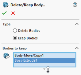
FIGURE 31.16 The Delete/Keep Bodies PropertyManager
Managing Bodies with the Split Feature
![]() The Split feature has essentially three functions:
The Split feature has essentially three functions:
- To split a single solid body into multiple solid bodies using planes, sketches, or surface bodies
- To save individual solid bodies to individual part files
- To reassemble individual part files that are saved into an assembly where the parts are all positioned in the same relative position as their corresponding bodies
The part of the Split feature that relates to this chapter is the first function mentioned, which is splitting a single solid body into multiple bodies using a sketch, a plane, or a surface body.
The Split feature cannot be used to split surface bodies. In fact, nothing in SolidWorks can split surface bodies. Only solid bodies can be split. Surface bodies can only be trimmed, so the effective workaround for not being able to split surface bodies is to copy the body, and then trim and keep one side of the copy and the other side of the original. This seems like a functionality oversight and would make a great enhancement request if you have ever come across the need for this functionality.
SPLITTING WITH A SKETCH
When you are using a sketch to split a single solid body into multiple bodies, the Split process works like this:
- Create a sketch with an open or closed loop; even a mixture of open and closed profiles will work. If it's open, the endpoints must be on an exterior edge or hanging off into space; they cannot actually be inside the boundaries of the solid. The one restriction is that the sketch can't be already used by another feature.
- Initiate the Split feature from the Features toolbar or from the menus by choosing Insert ➢ Features ➢ Split. You can do this with the sketch active, with the sketch inactive but selected, or with nothing selected at all.
- Click the Cut Bodies button. This doesn't actually cut anything; it only previews the split. When this is done, the resulting bodies appear in the window below and callout flags are placed on the part in the graphics window. Figure 31.17 shows the PropertyManager and the preview.
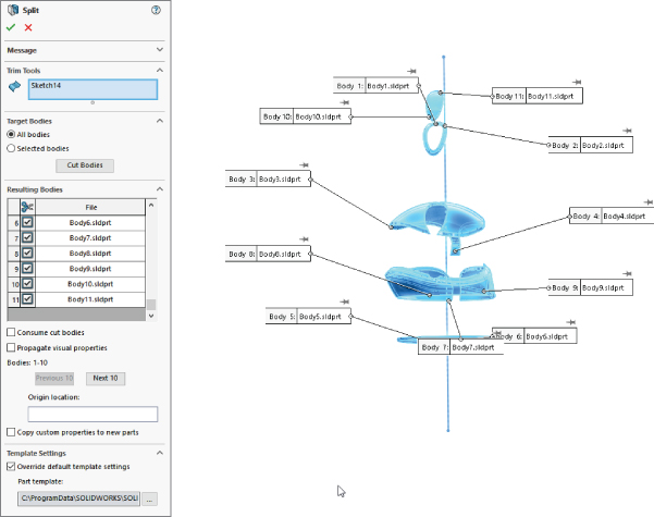
FIGURE 31.17 Using the Split feature
Check marks next to the body in the list indicate that the body will be saved to an external file. Using the Auto-Assign Names button will make the software assign filenames to all bodies and prepare to save them as external files, using the template information at the bottom of the PropertyManager.
The Consume Cut Bodies option removes, or consumes, any of the bodies that have a check mark.
SPLITTING WITH A PLANE
Splitting with a plane provides the same type of results and uses the same options as splitting with a sketch. However, you never have to worry about the plane being extended far enough, because the cut is made from the infinite extension of the plane. The only thing you have to worry about with a plane is whether it intersects the part.
SPLITTING WITH A SURFACE BODY
Surface bodies are used to split solid bodies for a couple of reasons. In the part shown in Figure 31.12, a surface body was used to make the split instead of a sketch or a plane, because both of those entities split everything in an infinite distance either normal to the sketch plane or in the selected plane. A surface body only splits to the extents of the splitting surface body. If you look closely at the part, you notice that a plane or sketch would lop off one side of the sphere on top of the object, but the small planar surface is limited enough in size to split only what is necessary.
Another advantage to using a surface body is that it isn't limited to a two-dimensional cut. The surface itself can be any type of surface, such as planar, extruded, revolved, lofted, or imported. Taking this a step further, the surface isn't limited to being a single face or a body resulting from a single feature; it could be made from several features that are put together as long as it's a single body and all the outer edges of the surface body are outside the solid body. If you examine the mouse part shown in Figure 31.3, you can see that it has splits made from multifeature surface bodies.
I mention splitting with surface bodies here because this is where I discuss the Split function, even though I haven't covered the surfacing functions yet. It may be useful to read parts of this book out of order; given how the topics interrelate, it's impossible to order them in such a way that some sections don't refer to a topic that hasn't yet been covered.
Adding Bodies Using the Insert Part Feature
![]() The Insert Part button can be found on the Features toolbar, or you can access this feature by choosing Insert ➢ Part from the menus.
The Insert Part button can be found on the Features toolbar, or you can access this feature by choosing Insert ➢ Part from the menus.
Insert Part enables you to insert one part into another part. When inserting the part, you have the option to insert solid bodies, axes, planes, cosmetic threads, surface bodies, and several other types of entities, including sketches and features. The PropertyManager interface for the Insert Part feature is shown in Figure 31.18.

FIGURE 31.18 The Insert Part PropertyManager
When you use Insert Part, there's no Insert Part feature that becomes part of the tree. Instead, a Part icon is shown with the name of the part being inserted as a feature. Notice that the basket part shown in Figure 31.13 also uses Insert Part to put together bodies to form a finished part.
WORKING WITH SECONDARY OPERATIONS
One commonly used technique has to do with secondary operations. For example, you may have designed a casting that needs several machining operations after it comes from the foundry. The foundry needs a drawing to produce the raw casting, and the machine shop needs a different drawing to tap holes, spot face areas, trim flash, and so on.
You can use configurations to do this by using Insert Part in another way. This has nothing to do with multiple body techniques, but this is the only place in this book where Insert Part is covered in much detail. One of the advantages of using Insert Part is that you no longer carry around the overhead of all the features in the parent part. It's as if the inserted part were imported. The configurations method forces you to carry around much more feature overhead. Of course, the downside is that now there's an additional file to manage, but this can be an advantage because many companies assign different part numbers to parts before and after secondary operations.
STARTING POINT
Looking back to the mouse shown in Figure 31.3, the main part has been split into several bodies. You can use Insert Part to insert the whole mouse into a new part where all the bodies except one are deleted, and then the remaining body serves as the starting point for a new part. Many additional features are needed on all the bodies that make up the mouse, such as assembly features, cosmetic features, functional features, and manufacturing features.
Using Intersect to Modify Bodies
![]() Intersect combines the capabilities of several surface and solid body tools. The tools that it combines are Split, Cut With Surface, Cut, Trim, Knit, and Thicken. Chapter 32, “Working with Surfaces,” will take another look at this feature because it can use surfaces. In this chapter, we just look at its capability with solids.
Intersect combines the capabilities of several surface and solid body tools. The tools that it combines are Split, Cut With Surface, Cut, Trim, Knit, and Thicken. Chapter 32, “Working with Surfaces,” will take another look at this feature because it can use surfaces. In this chapter, we just look at its capability with solids.
Intersect can use solid bodies, surface bodies, and planes as inputs, and the output will be a number of solid or surface bodies. Based on the inputs, the Feature interface shows the possible outcomes, and you just select the body regions you want to keep. Figure 31.19 shows this feature in action. There's a block centered on the origin and a sphere inside the block, also centered on the origin.
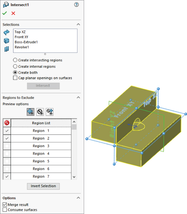
FIGURE 31.19 Splitting a solid with Intersect
In this example, the sphere is removed from the block, which is then split by the Top and Front planes, creating four possible solid regions. By excluding the sphere and one solid region, this feature produces the result shown on the right.
This tool combines existing solid and surface functionality from features like Trim, Combine, Cut With Surface, and Knit.
It is useful for replacing many Combine Add features. It pretty much combines anything that is possible. While Combine Add outputs one body, Intersect can output multiple bodies. Is also useful for creating volumes from internal cavities, without modifying the surrounding bodies.
Managing Bodies
Managing bodies in SolidWorks isn't as clean a task as managing parts in an assembly. As you work with bodies, you may discover some surprises in how bodies are managed. Body naming and merge/split issues are among some of the behaviors you will have to learn to deal with. This section prepares you for challenges involved in managing bodies in SolidWorks.
Using Body Folders
The top of the FeatureManager includes a pair of folders—one called Solid Bodies and the other called Surface Bodies (which only exist if you have multiple solid bodies or any surface bodies). They reflect the state of the model at the current position of the Rollback bar. As a result, the folders can change and even disappear as you roll the tree back and forth in history. Figure 31.20 shows the top of a FeatureManager that has both Solid and Surface Bodies folders. Notice that the number in parentheses after the name of the folder shows how many bodies are in that particular folder.
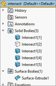
FIGURE 31.20 Body folders in the FeatureManager
An odd fact about these folders is that you are allowed to rename the folders, but the name changes never remain. If you go back to rename the folder again, the name that you previously assigned will display.
You may encounter another problem with the display of FeatureManager header items in general when they are set to Automatic display (which display only when they contain something). The Automatic setting for FeatureManager folder display works incorrectly from time to time. For this reason, I suggest using the Show option to display important folders. Figure 31.21 shows the Options page (Tools ➢ Options ➢ FeatureManager) that controls the visibility of folders.

FIGURE 31.21 Control the visibility of FeatureManager items
By right-clicking either of the bodies folders, you can select the Show Feature History option, which shows the features that have combined to create the bodies in an indented list under the body name. This view of the FeatureManager is shown in Figure 31.22. This option is very useful when you are editing or troubleshooting bodies.
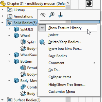
FIGURE 31.22 Using the Show Feature History option
Figure 31.22 also shows the other options in the right mouse button (RMB) menu. All the bodies in the folder can be alternatively shown or hidden from this menu, as well as deleted. Although the Hide or Show state of a body doesn't create a history-based feature in the tree, the Delete feature does, as discussed previously.
You can expand the Display pane in parts to show display information for bodies (see Figure 31.23). Display pane shows the colors assigned to the solid bodies, as well as the fact that several surface bodies exist but are hidden.
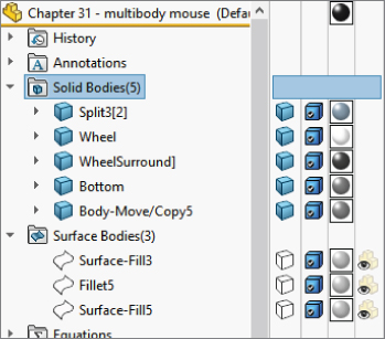
FIGURE 31.23 The Display pane showing information about solid and surface bodies
The folders also make bodies easier to identify, especially when combined with the setting found at Tools ➢ Options ➢ Display/Selection ➢ Dynamic Highlight From Graphics View. This setting quickly turns the body outline red if you move the mouse over the body in the Body folder.
Hiding or Showing Bodies
You can hide or show bodies in several ways. I've already described the method of using the bodies folders to hide or show all the bodies at once, but you can also right-click individual bodies in the folders to hide or show them using the RMB menu. Remember that with the context bars, you have the option to use them with the RMB menu as well as with left-click selections. I include all context bar options in the RMB menu generically.
If you can see a body in the graphics area, then you can right-click the body and select Hide under the Body heading. This works for both solids and surfaces. The Display pane, shown to the right of the FeatureManager in Figure 31.23, can also be used to hide or show bodies, change body transparency and appearance, and change the Display mode of bodies. Display pane is a handy tool for visualization options.
When you are hiding or showing bodies from the FeatureManager, but not using the bodies folders and using the features themselves instead, things get a little complicated. If you want to hide or show a solid body, you can use any feature that's a parent of the body to hide or show the body. For example, you can use the Shell feature in the mouse model to hide or show all the bodies of which it's a parent.
Other facts that you need to know about bodies and their hide or show states are that the Hide or Show feature is both configurable and dependent on the rollback state. As a result, if you hide a body and then roll back, it may appear again and you have to hide it again. Then, if you roll forward, the state changes again. Also, a body can be hidden in one configuration, and when you switch configurations, it remains hidden. All the unwritten rules make it rather frustrating at times to work with bodies.
Display State functionality in multibody parts is an extremely handy and a very fast way to change color, transparency, or display modes for individual bodies. The best way to handle this is to expand the Display pane and control Hide/Show, Display Mode, Appearance, and Transparency directly from the Display pane. Figure 31.24 shows the Display pane in action on a multibody part.

FIGURE 31.24 Using the Display pane to control multibody display states
In Figure 31.24, the FeatureManager panel is split so you can see the configurations and Display State information alongside the bodies folder and Display pane. If you are familiar with display states in assemblies, it's the same as for bodies.
You can assign different materials to each body. If different parts are made of different materials, the only situations in which I would model this way would be overmolds, where multiple materials are molded onto one another, and inseparable subassemblies, like purchased components such as screws with captive washers or a circuit board with rivets. To apply materials to bodies, right-click the body in the Solid Bodies folder and select Material.
![]() Another tool in SolidWorks is called Show Hidden Bodies. It works like its assembly equivalent Show Hidden Components. In a part with hidden bodies, right-click an empty space in the graphics window and select Show Hidden Bodies. The interface shown in Figure 31.25 is displayed, visible become hidden and hidden become visible, and the command uses a special cursor. This tool comes in handy in complex design situations where you have a large number of bodies or when you simply need to visualize existing bodies that are not shown.
Another tool in SolidWorks is called Show Hidden Bodies. It works like its assembly equivalent Show Hidden Components. In a part with hidden bodies, right-click an empty space in the graphics window and select Show Hidden Bodies. The interface shown in Figure 31.25 is displayed, visible become hidden and hidden become visible, and the command uses a special cursor. This tool comes in handy in complex design situations where you have a large number of bodies or when you simply need to visualize existing bodies that are not shown.
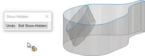
FIGURE 31.25 Show Hidden Bodies interface and cursor
For faster (solid or surface) body visibility changes, use these shortcuts:
- Tab with the cursor over a body in the graphics window will hide a body.
- Shift+Tab with the cursor over a hidden body will show the body. (This works best with the preview techniques of selecting a body from the bodies folders or Ctrl+Shift+Tab.)
- Holding Ctrl+Shift+Tab previews all hidden bodies. Clicking on the temporarily shown bodies will show the selected bodies.
- Selecting hidden bodies in the Solid or Surface Bodies folders will preview those bodies until they are unselected. You can then press Shift+Tab with the cursor over any body to show that body.
- Use the Tab, Shift+Tab, and Ctrl+Shift+Tab shortcuts to hide/show bodies.
Deleting Bodies
![]() I've already mentioned that you can delete bodies using the Delete/Keep Bodies feature and that this feature exists in the tree of the part. This feature previously was called Delete Bodies.
I've already mentioned that you can delete bodies using the Delete/Keep Bodies feature and that this feature exists in the tree of the part. This feature previously was called Delete Bodies.
Delete/Keep Bodies doesn't affect file size or rebuild speed. In fact, I find it difficult to come up with examples of when you should use it or if a throwaway body somehow remains in the part. Some people use this feature to clean up the organization of the tree. However, all it does beyond hiding bodies is to make them inaccessible (without rolling back or editing the feature). Other users insist on keeping the tree free of extraneous bodies and immediately delete bodies that have been used. To me, this technique replaces one kind of clutter with another, and it means that tools that should be available to you (solid or surface bodies) aren't available unless you reorder the Delete Body feature down the tree and/or roll back. In any case, this is really a matter of personal working style and not of any great importance.
Some export filetypes will export all the bodies without warning. Thus, the easiest way to make sure that a file doesn't have extra bodies for the export is to just add a Delete Body feature that removes the extraneous bodies that aren't included in the final part. Also, always re-import any exported data to make sure the export worked correctly.
Renaming Bodies
Notice that the bodies that you see in the folders have been named for the last feature that touched a given body. That means that the bodies keep changing names. If you deliberately rename a body, it retains the name you give it through future changes. You should follow the same rules for naming bodies as you do for naming features. It isn't necessary to rename every body, but if you will use one body frequently and need to select it from the FeatureManager, renaming it is very useful.
Tutorials: Working with Multibodies
This section contains various short examples of multibody techniques in order from easy to more difficult.
Merging and Local Operations
This tutorial gives you some experience using the Merge Result option and using features on individual bodies to demonstrate the local operations functionality of multibody modeling. Try these steps:
- Start a new part, and sketch a rectangle centered on the origin on the Top plane. Make the rectangle any size you like.
- Extrude the rectangle to roughly one-third of its smaller dimension.
- Open a second sketch on the Top plane. Hide the first solid body by right-clicking it in either the FeatureManager or the graphics window.
- Show the sketch for the first feature, and draw a second rectangle on the far side of the rectangle from the origin. Make sure the second rectangle gets two Coincident relations to the first sketch at two corners so the rectangles are the same width. When the sketch is complete, hide the sketch that was shown.
- Extrude the second rectangle to about two-thirds of the depth of the first rectangle.
- Shell out the second extrusion by removing two adjacent sides, as shown in Figure 31.26. One of the sides is the top, and the other is the shared side with the hidden body. The body that should be hidden at this point is shown as transparent in the image for reference only. The body was made transparent to make it easier to select the face of the second body.

FIGURE 31.26 Shelling two sides of a block
- Show the first body either from the Solid Bodies folder at the top of the tree or from the RMB menu of the first solid feature in the tree.
- Shell the bottom side of the first body, so the cavities in the two bodies are on opposite sides.
- Combine the two bodies using the Combine tool you can find by choosing Insert ➢ Features ➢ Combine. This feature is also available via the RMB menu in the Solid Body folder. Select the Add option and select the two bodies. Click OK to finish the feature. Figure 31.27 shows the finished part.

FIGURE 31.27 The finished part
Splitting and Patterning Bodies
This tutorial guides you through the steps to delete a pattern of features from an imported body, separate one of the features, and then pattern it with a different number of features. This introduces some simple surface functions in preparation for Chapter 32, “Working with Surfaces.” Follow these steps:
- Open the Parasolid file from the download materials called
Chapter 31 – Bonita Tutorial.x_t. - Using the Selection Filter set to filter the Face selection (the default hotkey for this is X), select all the faces of the leg. You can use window-selection techniques to avoid clicking each face.
- Click the Delete Face button on the Surfaces toolbar, or access the command by choosing Insert ➢ Face ➢ Delete from the menus. Make sure that the Delete And Patch option is selected. The selected faces and the Delete Face PropertyManager should look like Figure 31.28. Click OK to accept the feature.
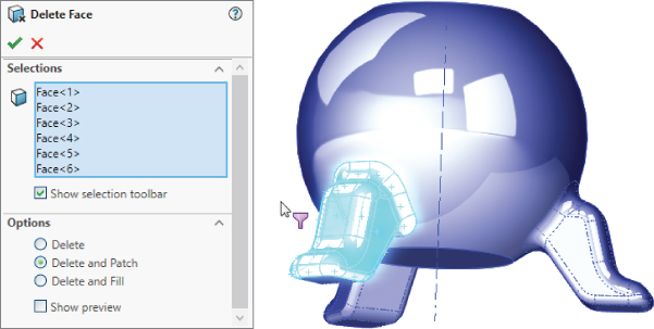
FIGURE 31.28 The Delete Face PropertyManager
- Repeat the process for a second leg, leaving the third leg to be separated from the rest of the part and patterned.
- After the two legs have been removed, click the outer main spherical surface, and then choose Insert ➢ Surface ➢ Offset from the menus. Set the offset distance to zero. Notice that a Surface Bodies folder is now added to the tree, near the top.
- Hide the solid body. You can do this from the Solid Bodies folder, from the FeatureManager, or from the graphics window. Hiding the solid leaves the offset surface, and there should be three holes in it.
- Select one of the edges of the hole indicated in Figure 31.29 and press the Delete key. The Choose Option dialog box will appear. Select the Delete Hole option rather than the Delete Feature option. The Delete Hole operation becomes a history-based feature in the model tree. Before moving on to the next step, remember that you may need to turn off the Selection Filter for faces.
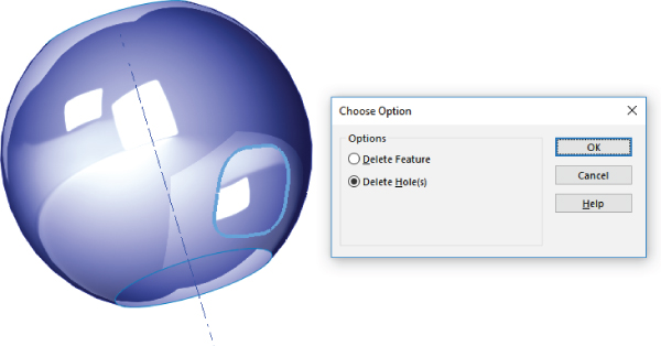
FIGURE 31.29 Using the Delete Hole option
- After you delete the hole from the surface body, change the color of the surface body the same way you changed the colors of parts, faces, and features.
- Click the surface body in the Surface Bodies folder, and either press the Delete key or select Delete Body from the RMB menu. Click OK to accept the feature. This will place a Delete Body feature in the tree. It will keep the body from getting in the way when it isn't needed. This isn't a necessary step, but many people choose to use it. (Suppress the Delete Body feature, because this body is needed again later.)
- Now show the solid body. You'll notice that the color of the surface conflicts with the color of the solid. This mottled appearance is due to the small approximations made by the rendering and display algorithms.
- Initiate the Split feature by choosing Insert ➢ Features ➢ Split from the menus or clicking the Features toolbar. Use the surface body to split the solid body. Click the Cut Part button, and select the check boxes in front of both bodies in the list. Click OK to accept the feature. Notice that now the Solid Bodies folder indicates that there are two solid bodies.
- From the View menu, select the display of Temporary Axes. Initiate a Circular Pattern feature, selecting the temporary axis as the axis and the split-off leg in the Bodies To Pattern selection box. Set it to four instances, as shown in Figure 31.30.
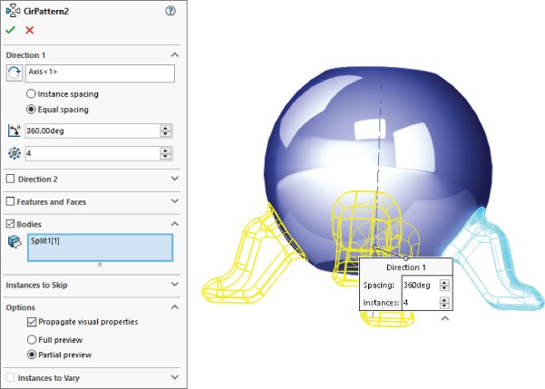
FIGURE 31.30 Patterning a body
- Use the Combine feature to add together all five bodies. You can access this feature by choosing Insert ➢ Features ➢ Combine from the menus.
The Bottom Line
Beginning to understand how to work with multiple bodies in SolidWorks opens a gateway to a new world of modeling possibilities. Like in-context design, multibody modeling is definitely something that you have to go into with your eyes open. You'll experience difficulties when using this technique, but you'll also find new possibilities that weren't available with other techniques. The key to success with multibody techniques is understanding the capabilities and limitations of the tools.
When using a model with the multibody approach, make sure you can identify a reason for doing it this way rather than using a more conventional approach. Also keep in mind the list of applications or uses for multibody modeling mentioned in this chapter. For some types of work, such as using the SolidWorks Mold tools and weldments, you cannot avoid multibody modeling.
- Master It Use the following methods to create multibodies within a part file:
- Multiple closed loops within a single Extrude feature
- Multiple disjoint features of different types within a single part
- Creating two solid features that merge to create a single body, then turning off the Merge Result option in the second feature to create a second body
- A Cut feature that separates a single body into multiple bodies
- Splitting a single body with a plane
- Master It Using one or more of the models created in the previous exercise, use the RMB tools from the bodies folders and the Display pane to perform the following functions to body-level geometry:
- Hide and Show
- Rename
- Change Color
- Apply Material
- Change Display State
- Make a Body Transparent
- Master It Starting with one of the parts you created in the first exercise, use Insert Part to pull one of the other multibody parts into the current one. Then use Insert Into New Part to push the current part into a new part. Notice how all the parts are listed as bodies when treated in this way. Next, use Combine to merge any bodies that are touching.