28.5 Computer Simulations Using NIST-Gas Data
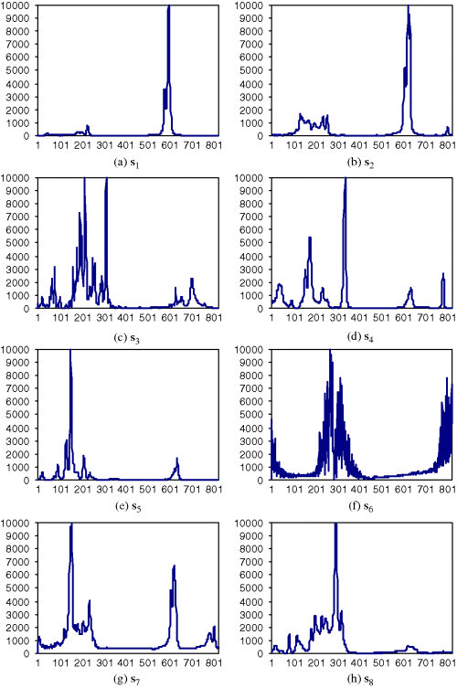
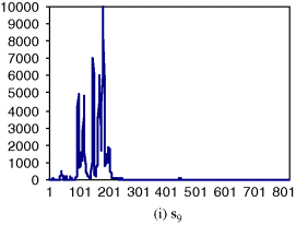
In order to demonstrate the utility of KFSSE in spectral estimation, identification, and quantification, the spectral signature vectors in the data set Δ to be used for experiments were those in Figure 1.10 available at the National Institute of Standard Technology (NIST)'s website http://www.nist.gov/srd/nist35.htm. It contains nine agent signatures ![]() , eight of them,
, eight of them, ![]() are composed of 880 bands, and only one of them, s1, consists of 825 bands.
are composed of 880 bands, and only one of them, s1, consists of 825 bands.
As mentioned previously, since KFSCSP technique developed in this chapter is signature a vector-based and not an image-based technique, KFSSE, KFSSI, and KFSSQ are not designed for classification. Therefore, their performance will be evaluated by signature vector-based spectral measures such as SAM and SID rather than image classifiers.
28.5.1 KFSSE
To implement KFSSE, the system gain cl in (28.5) was set to be 1 for all ![]() , the standard deviation of the state noise v, σv, was empirically set to 103 and the standard deviation of the measurement noise u, σu, was chosen to make SNR = 30 dB, where the SNR was defined before. It should be noted that throughout our extensive experiments, the results demonstrated that KFSSE was robust to the selection of σu and σv. More specifically, once the value of σv was greater than 103, the σu had limited impact on the performance of KFSSE. Therefore, for KFSSE implemented in this chapter, the σu and σv were fixed at 30 dB and 103, respectively.
, the standard deviation of the state noise v, σv, was empirically set to 103 and the standard deviation of the measurement noise u, σu, was chosen to make SNR = 30 dB, where the SNR was defined before. It should be noted that throughout our extensive experiments, the results demonstrated that KFSSE was robust to the selection of σu and σv. More specifically, once the value of σv was greater than 103, the σu had limited impact on the performance of KFSSE. Therefore, for KFSSE implemented in this chapter, the σu and σv were fixed at 30 dB and 103, respectively.
Figure 28.6(a)–(e) shows KFSSE-estimated spectra of the nine reflectance spectra in Figure 1.10. Since the values of the corresponding estimation errors obtained by KFSSE were very small, Figure 28.7(a)–(e) shows the plots of taking logarithm function of ratios of estimation errors to their corresponding reflectance spectra in Figure 1.10 to have better visual assessment.
Figure 28.7 Ratios of the estimation errors to the five reflectance spectra in Figure 1.10 by taking the logarithm function.
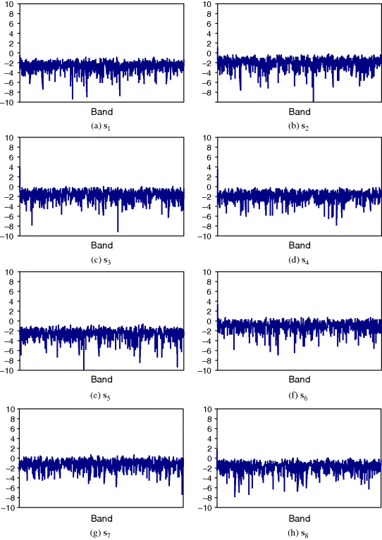
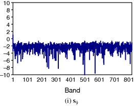
According to Figure 28.7, KFSSE performed very effectively in estimating spectral signatures with estimation errors nearly close to zero. Obviously, the large estimation errors always occurred at wavelengths where their spectral values had drastic changes. On the contrary, if there was a smooth transition between two wavelengths, the estimation errors were relatively small.
28.5.2 KFSSI
Two scenarios were implemented by KFSSI for subpixel target identification and mixed target identification with the target signature vector t to be identified assumed to be either known or unknown.
28.5.2.1 Subpixel Target Identification by KFSSI
First of all, we used Figure 4.1 to simulated a subpixel target embedded into a pixel vector. Assume that the subpixel target was the s6, and the background was s7. Figure 28.8(a) shows how a subpixel target t1 of ¾ pixel size was simulated. In order to simulate the subpixel target t1, we first simulated 1 pixel vector specified by s6 which was considered as the background signature and 3 pixel vectors specified by s7 to form a 4-pixel square panel as shown at the bottom layer in Figure 28.8(a). The 4-pixel square panel was then shrunk to its ¼ size by averaging all 4 pixel vectors to a 4-pixel square panel with the same spatial resolution 1.56 m shown at the top layer of Figure 28.8 where each pixel vector in the shrunk 4-pixel square panel was only ¼ size of its corresponding pixel vector at the bottom layer of Figure 28.8(a) as a result of ![]() . This shrinking process is described in Figure 28.8. The shrunk 4-pixel vector at the top layer in Figure 28.8(a) was the desired pixel vector p1 that contained a subpixel target t1 of ¾ pixel size specified by Calcite. Similarly, two pixel vectors p2 and p3 shown in Figure 28.8(b) and (c) were also simualted in the same fashion as results of
. This shrinking process is described in Figure 28.8. The shrunk 4-pixel vector at the top layer in Figure 28.8(a) was the desired pixel vector p1 that contained a subpixel target t1 of ¾ pixel size specified by Calcite. Similarly, two pixel vectors p2 and p3 shown in Figure 28.8(b) and (c) were also simualted in the same fashion as results of ![]() and
and ![]() , respectively, where p2 contained a subpixel target t2 of ½ pixel size specified by s7 and p3 contained t1 of ¼ pixel size specified by s6.
, respectively, where p2 contained a subpixel target t2 of ½ pixel size specified by s7 and p3 contained t1 of ¼ pixel size specified by s6.
Figure 28.8 Simulations of subpixel target panels: (a) subpixel target panel with ¼ s6 + ¾ s7; (b) subpixel target panels with ½ s6 + ½ s7; (c) subpixel target panel with ¾ s6 + ¼ s7.

KFSSI was implemented to identify an unknown subpixel target panel generated by the three panels p1, p2, and p3 in Figure 28.8(a)–(c) via a database Δ = {s6, s7}. The identification was carried out by first setting the values for both σu and σv, then randomly choosing a matching signature vector from the database Δ to match the unknown subpixel target panel according to (28.8) and (28.9), and finally identifying the unknown subpixel target panel as the one which yielded the minimum LSE. The resulting LSE corresponding to different sizes of subpixel target panels are tabulated in Table 28.1 with various values of the standard deviation of noise u, σu and also with ![]() . However, it should be noted that the selection of σu empirically depended upon the target signature vector to be used for experiments. The simulated data conducted in this section were only used to demonstrate and illustrate the utility and effectiveness of KFSSI in signature identification under the impact of the parameter σu. In doing so, we had experimentally adjusted the value of σu in accordance with our simulation data to dictate the impact of subpixel target size on the performance shown in Table 28.15. Figure 28.9(a) and (b) plot LSEs of s6 and s7, respectively, versus the values of σu for three sizes of subpixel targets, ¾, ½, and ¼, where the values of σu varied from 10 to 1000 with step size set to be 10.
. However, it should be noted that the selection of σu empirically depended upon the target signature vector to be used for experiments. The simulated data conducted in this section were only used to demonstrate and illustrate the utility and effectiveness of KFSSI in signature identification under the impact of the parameter σu. In doing so, we had experimentally adjusted the value of σu in accordance with our simulation data to dictate the impact of subpixel target size on the performance shown in Table 28.15. Figure 28.9(a) and (b) plot LSEs of s6 and s7, respectively, versus the values of σu for three sizes of subpixel targets, ¾, ½, and ¼, where the values of σu varied from 10 to 1000 with step size set to be 10.
Table 28.15 LSE corresponding to different sizes of subpixel target panels (s6) according to (28.10) via Δ = {s6, s7 }

Figure 28.9 Relationship between ![]() and the corresponding LSE according to different sizes of the subpixel target.
and the corresponding LSE according to different sizes of the subpixel target.
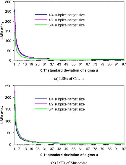
For example, in order to correctly identify the subpixel panel with ¼ size of a pixel, according to Table 28.1, the σu must be greater than 450 compared to the subpixel panel with ¾ size of a pixel which only requires σu smaller than 550. As pointed out at the end of Section 28.4, the selections of σu and σv had significant impact on the performance of KFSSI and must be chosen appropriately in order to achieve acceptable LSEs. According to our exepriments, once σv was fixed, the minimum value of σu could be set approximately at the same order of magnitude in order to correctly identify the subpixel target as Calcite. Table 28.16 is included here to illustrate the relationship between σv and σu with three different values of σv, and seven subpixel targets of size specified by (1/8, 2/8, 3/8, 4/8, 5/8, 6/8, and 7/8).
Table 28.16 The relationship between σv and σu with s6 as target embedded into s7
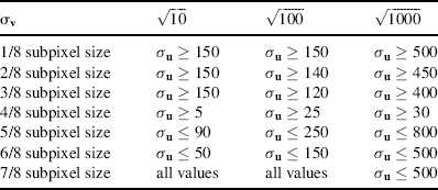
Table 28.17 tabulates the same experiments that were performed by SAM and SID, with the SID values included in parentheses where there was impossible for SAM and SID to detect the subpixel target panel if its size is smaller than ½ size of a panel. On the contrary, KFSSI could detect subpixel targets correctly even its size was smaller than ½ size of a pixel as long as σu was chosen to be the values tabulated in Table 28.2.
Table 28.17 Estimated size of subpixel panels with s6 as target embedded into s7 by SAM and SID.
| Subpixel size | s6 | s7 |
| 1/8 | 1.1180 (1.6294) | 0.1570 (0.0702) |
| 1/4 | 0.9410 (1.1529) | 0.3340 (0.2206) |
| 3/8 | 0.7525 (0.8004) | 0.5226 (0.4211) |
| 1/2 | 0.5651 (0.5282) | 0.7099 (0.6636) |
| 5/8 | 0.3911 (0.3172) | 0.8840 (0.9492) |
| 3/4 | 0.2380 (0.1579) | 1.0370 (1.2890) |
| 7/8 | 0.1081 (0.0483) | 1.1669 (1.7161) |
The above experiments demonstrated an important advantage of KFSSI. More specifically, KFSSI could perform well in the subpixel identification, even if the size of a subpixel target was less than ½ of ground sampling distance, that is, pixel resolution, which could not be achieved by any other spectral measure.
28.5.2.2 Mixed Target Identification by KFSSI
In order to make our experiments more interesting and appealing, we further simulated a mixed pixel vector tmix by mixing ¼ s3, ¼ s4, ¼ s6, and ¼ s7 together. In other words, tmix was simulated by mixing equal amount of abundance among the four signature vectors as follows:
(28.15) ![]()
shown in Figure 28.1. In this case, no signature vector was preferred to another. KFSSI was used to identify unknown target signature vector t present in the mixed pixel vector tmix using the database Δ = {s3, s4, s6, s7}. According to the composition of tmix, all the four signature vectors had equal opportunity to be identified as the target signature vector. The resulting LSEs corresponding to different matching components to the mixed pixel vector are shown in Table 28.18.
Table 28.18 LSE between mixed pixel and different matching signature vectors according to (28.10)

28.5.3 KFSSQ
This section presents experiments to further demonstrate the use of KFSSQ in quantification of subpixel targets and target signature vectors present in mixed pixels. However, unlike KFSSI, which was used to identify an unknown target signature vector t, KFSSQ could also be implemented for the target signature vector t, which was either unknown or known as a priori. It should also be noted that unlike KFSSI, there was no state noise vector v in the state equation (28.12) implemented by KFSSQ.
28.5.3.1 Subpixel Target Identification by KFSSQ
Using the same subpixel targets t1, t2, and t3 simulated in Section 28.4.2.1, we implemented KFSSQ to quantify these three Calcite-simulated subpixel target panels t1, t2, and t3 specified by ¾, ½, and ¼ size of a pixel in Figure 28.8 with two scenarios described in the following examples.
Example 28.6
(Target signature vector t is known)
This example assumed that the target signature vector t was known to be s6. In this case, the pair of (28.11) and (28.12) was implemented to quantify three subpixel targets t1, t2, and t3 of s6. It should be noted that since the subpixel target panels only occupied part of a pixel; its size could be interpreted as portion of abundance fraction in terms of percentage. In this case, the three subpixel target panels t1, t2, and t3 with size of ¾, ½, and ¼ could be considered as targets with abundance fractions 75%, 50%, and 25%, respectively, as indicated in Table 28.19.
As shown in Table 28.19, KFSSQ-estimated quantification results were very accurate with appropriate chosen values of σu with no occurrence of σv.
Table 28.19 KFSSQ-estimated abundance fractions.
| KFSSQ | Quantification | σu in KFSSQ |
| t1 = 25% s6 | 0.2527 | 55000 |
| t2 = 50% s6 | 0.5000 | 31000 |
| t3 = 75% s6 | 0.7493 | 18000 |
Example 28.7
(Target signature t is unknown)
Unlike Example 28.1, the prior knowledge of target signature vector t was not given in this example. In this case, KFSSQ must first identify via (28.5) and (28.6) the target signature vector t that specified the three subpixel targets t1, t2, and t3 where KFSSE was used for this purpose and the estimated target denoted by ![]() . The estimated
. The estimated ![]() was then used to replace t in (28.11) to produce the abundance vector
was then used to replace t in (28.11) to produce the abundance vector ![]() specified by (28.12) in Table 28.6. As a result, there were two different values of σu used for measurement noise in KFSSQ, one in (28.5) used for KFSSE and the other in (28.13) used for KFSSQ. Since both were not correlated, they could be determined independently as tabulated in Table 28.20.
specified by (28.12) in Table 28.6. As a result, there were two different values of σu used for measurement noise in KFSSQ, one in (28.5) used for KFSSE and the other in (28.13) used for KFSSQ. Since both were not correlated, they could be determined independently as tabulated in Table 28.20.
Due to the fact that KFSSE could not correctly estimate the target signature vector t provided that the abundance of subpixel target t was below 50%, which was reasonable, the results for the size of subpixel target being ¼ are not included in Table 28.20.
Table 28.20 KFSSQ-estimated abundance fractions.

28.5.3.2 Mixed Target Quantification by KFSSQ
In this subsection, we used the same mixed pixel vector, tmix simulated in Section 28.4.2.2 for further experiments. KFSSQ is implemented to quantify the four signature vectors, s3, s4, s6, and s7, each of which shared a 25% abundance fraction in the pixel vector tmix. Like Section 28.4.3.1 of subpixel target quantification, two scenarios were also considered.
Example 28.8
(All the four target signatures are known)
This example assumed that all the four signature vectors were known. The pair of (28.11) and (28.12) was implemented for KFSSQ. Table 28.21 tabulates the quantification results of the four signature vectors with their appropriately chosen values of σu. However, it should be noted that the sensitivity of σu was generally determined by various applications. For example, when KFSSI and KFSSQ were implemented, the results would be sensitive to the value chosen for σu as shown in Tables 28.18 and 28.20. On the other hand, if KFSSE was implemented as an estimator, the results would be rather robust to the σu.
As we can see from Table 28.21, KFSSQ-estimated abundance fractions of all the four signature vectors were very accurate and close to true values.
In order to make comparison, the results produced by FCLS were also included and tabulated in Table 28.22, where their results comparable to those obtained in Table 28.21.
Table 28.21 Results of implementing KFSSQ for mixed pixel with target signature vectors known.
| KFSSQ | Quantification results | σu |
| 25% s3 | 0.2563 | 47000 |
| 25% s4 | 0.2519 | 45000 |
| 25% s6 | 0.2518 | 51000 |
| 25% s7 | 0.2524 | 51000 |
Table 28.22 The abundance fractions of the four target signature vectors in tmix estimated by FCLS.
| FCLS | Quantification results |
| 25% s3 | 0.2500 |
| 25% s4 | 0.2500 |
| 25% s6 | 0.2500 |
| 25% s7 | 0.2500 |
Example 28.9
(Sensitivity of KFSSQ to σu)
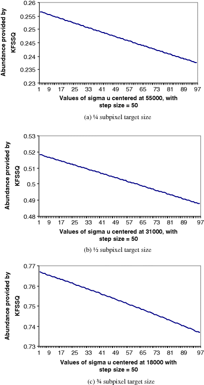
This experiment was designed to investigate sensitivity of KFSSQ to the values of σu in quantification of subpixel targets. Performing similar experiments conducted for Example 28.1, the results tabulated in Table 28.22 were used to select three proper ranges of σu for three different target sizes (1/4, 1/2, and 3/4) for correct quantification. Figure 28.10(a)–(c) plots their results of KFSSQ for three different target sizes (1/4, 1/2, and 3/4) versus σu with step size 0.1.
The curves plotted in Figure 28.10(a)–(c) show that the abundance fractions quantified by KFSSQ were inversely proportional to the values of σu, where the curves were flatted out throughout the range of σu. This indicates that KFSSQ was indeed very sensitive to the value of σu where an appropriate value of σu must be carefully selected in order to perform correct quantification for subpixel targets.
Finally, a concluding remark on the selection of σu is worthwhile. Since there is generally no prior knowledge available for analysis, it is impossible to determine an appropriate value for σu a priori. A general approach is to use a trial-and-error approach to obtain a posteriori knowledge that can help to determine an adequate range of the σu. From there, the values for σu can be properly selected by further experiments. Nevertheless, a common guideline is that the more similar the target signature is to signatures in the database, the smaller is the σu required.
Figure 28.10 Results of KFSSQ versus values of σu for different sizes of the subpixel target.
