32.5 Synthetic MR Brain Image Experiments
In this section, a series of experiments were conducted via synthetic images to substantiate the utility of OC-ICA in MR image analysis and to demonstrate its advantages over the traditional ICA.
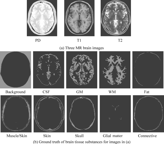
The synthetic images to be used for experiments in this section are the axial T1, T2, and proton density MR brain images (with 5-mm section thickness, 0% noise, and 0% intensity nonuniformity) resulting from the MR imaging simulator of McGill University, Montreal, Canada (available at www.bic.mni.mcgill.ca/brainweb/). The image volume provided separate volumes of tissue classes, such as CSF, GM, WM, bone, fat, and background. The use of these web MR brain images is to allow researchers to reproduce our experiments for verification. Figure 32.2(a) shows three MR brain images with provided specifications where the first image is obtained by modality = PD, protocol = ICBM, phantom_name = normal, slice_thickness = 5 mm, noise = 0%, INU (intensity nonuniformity) = 0%, the second image by modality = T1, protocol = ICBM, phantom_name = normal, slice_thickness = 5 mm, noise = 0%, INU = 0%, and the third image by modality = T2, protocol = ICBM, phantom_name = normal, slice_thickness = 5 mm, noise = 0%, INU = 0%. Figure 32.2(b) provides the ground truth also available on website www.bic.mni.mcgill.ca/brainweb/ for brain tissue substances in the images in Figure 32.2(a), which will be used to verify the results obtained for our experiments.
Figure 32.2 Synthetic MR images along with ground truth of brain tissue substances in images.
Despite the fact that there are many other brain tissue substances such as fat, bone, and blood that also constitute the brain, the three main tissue substances, CSF, GM, and WM are usually of major interest for clinical diagnosis, and these tissue signatures can be generally obtained by their anatomical structures. It has been shown in Hahn and Peitgen (2000) that the skull had significant effects on tissue classification. In this case, the skull signature was specifically included in the signature matrix as a separate and unwanted signature for signature removal. In addition, all signatures other than CSF, GM, WM, and skull were of no interest in brain tissue classification; they could be considered as the background signatures as a whole for background suppression. Accordingly, to implement the LSMA, the signature matrix M is specified by M = [CSF GM WM skull B], where the background signature B was obtained by averaging the signatures of skin, muscle, fat, and glial matter, connective with their training samples extracted in Figure 32.3 according to the ground truth provided in Figure 32.2(b). In the following experiments, LSOSP, NCLS, and FCLS are implemented for spectral unmixing using one of the three major brain tissue substances, CSF, GM, and WM, as the desired signature d with other signature plus skull and background signatures as unwanted signatures used for background suppression.
Figure 32.3 Tissues training sample regions for CSF, GM, WM, skull, muscle, connective, skin, fat, and glial matter of synthetic brain MR images.

Two experiments were conducted by operating LSMA on (1) the three original MR images shown in Figure 32.2 without using BEP and (2) the three original MR images combined with six BEP-generated bands (auto correlated and cross-correlated bands).
Since it has been shown in Wong (2008) that operating LSMA on the three original MR images combined with three BEP-generated bands (i.e., cross-correlated bands) produced results slightly worse than those combined with six BEP-generated bands (i.e., auto correlated and cross- correlated bands), the figures produced by experiments using three cross-correlated band images are not included here, but rather referred to Wong (2008) to avoid unnecessary duplication.
Experiment 32.1 Operating LSMA on the original three MR images
Figures show classification of CSF, GM, and WM in terms of their unmixed results as PVE produced by the LSOSP, NCLS, and FCLS using the original three MR images with 0%, 5%, 10%, and 20% noise INU fields.
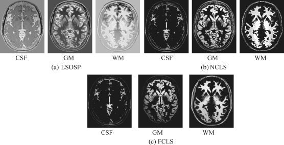
By visual inspection, NCLS produced the best classification in terms of PVE via unmixed results of CSF, GM, and WM in the original MR images. In particular, WM was classified with less false classification compared to LSOSP and FCLS. FCLS was able to classify CSF and GM tissues; however, the background of the MR image was falsely classified into WM. On the other hand, LSOSP showed the worst classification results. Although the important brain tissues CSF, GM, and WM could be distinguished from one another, the contrast of these tissues against the background was not as clear as the constrained techniques, NCLS and FCLS. Furthermore, Figures 32.4–32.7 show that the PVE results were gradually reduced as the intensity of INU fields was increased from 0% to 20%. Visual assessment also showed that the unconstrained method, LSOSP, had less effect from the INU fields than NCLS and FCLS had. By contrast, NCLS was the one that had most effects from the INU fields. For example, the top portion of the GM tissue in Figure 32.7(b) could clearly identify the corruption effect resulting from the INU field. In order to conduct a quantitative study of PVE by unmixed abundance fractions, the 3D ROC analysis developed in Chapter 3 was used for performance evaluation. Figures 32.8–32.11 show the mean classification rates of 3D ROC curves along with three respective 2D ROC curves for INU fields of various intensities: 0%, 5%, 10%, and 20%.
Figure 32.4 Classification of CSF, GM, and WM by their unmixed results in the original synthetic MR images with 0% noise INU fields produced by (a) LSOSP, (b) NCLS, and (c) FCLS.
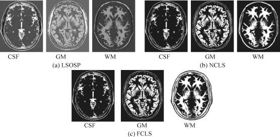
Figure 32.5 Classification of CSF, GM, and WM by their unmixed results in the original synthetic MR images with 10% noise INU fields produced by (a) LSOSP, (b) NCLS, and (c) FCLS.
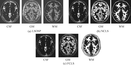
Figure 32.6 Classification of CSF, GM, and WM by their unmixed results in the original synthetic MR images with 10% noise INU fields produced by (a) LSOSP, (b) NCLS, and (c) FCLS.
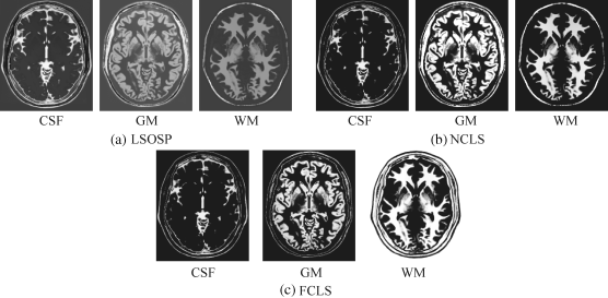
Figure 32.7 Classification of CSF, GM, and WM by their unmixed results in the original synthetic MR images with 20% noise INU fields produced by (a) LSOSP, (b) NCLS, and (c) FCLS.
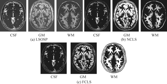
Figure 32.8 3D ROC analysis of LSOSP, NCLS, and FCLS methods operating original MR images with 0% noise INU fields.
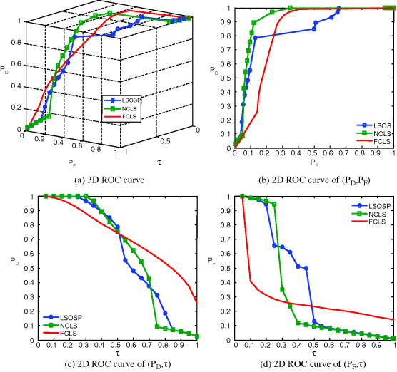
Figure 32.9 3D ROC analysis of LSOSP, NCLS, and FCLS methods operating original MR images with 5% noise INU fields.
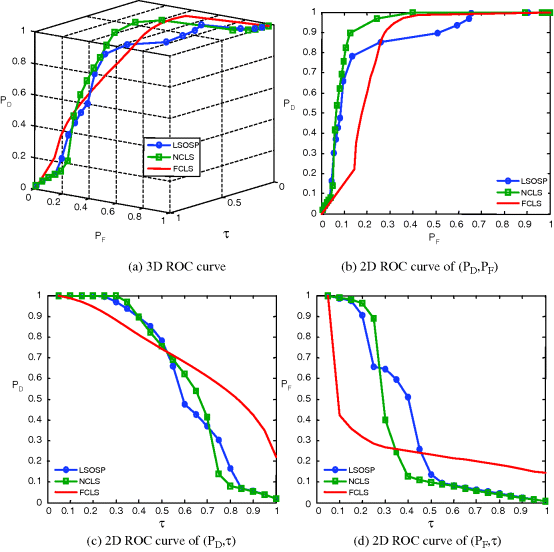
Figure 32.10 3D ROC analysis of LSOSP, NCLS, and FCLS methods operating original MR images with 10% noise INU fields.

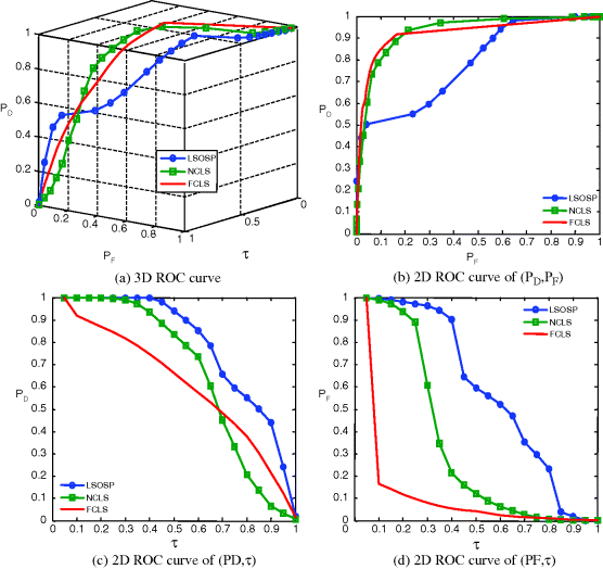
Figure 32.11 3D ROC analysis of LSOSP, NCLS, and FCLS methods operating the original MR images with 20% noise INU fields.
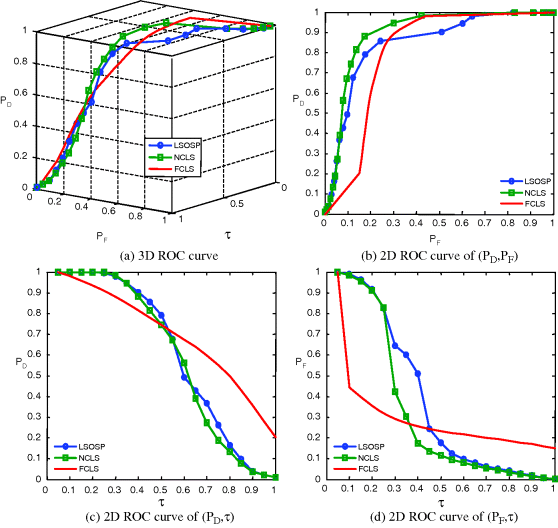
As shown in Figures 32.8–32.11, NCLS clearly outperformed the other two methods: LSOSP and FCLS.
Experiment 32.2
Operating LSMA on the three original MR images combined with six BEP-generated bands (autocorrelated and cross-correlated bands) as shown in Figure 32.12 where the signature matrix M = [CSF GM WM skull B] is used to unmix CSF, GM, and WM. The noise used was specified by 0%, 5%, 10%, and 20% INU fields.
Figure 32.12 An example of nine-band image cube obtained from three origin MR images, three cross- correlated, and three autocorrelated band images.

Following the same treatment conducted for Experiment 32.1, Figures 32.13–32.16 show classification of CSF, GM, and WM in terms of PVE by their unmixed results produced by LSOSP, NCLS, and FCLS using expanded MR images composed of the original three MR images, three autocorrelated, and three cross-correlated bands generated by the BEP with four different noise INU fields of 0%, 5%, 10%, and 20%.
Figure 32.13 Classification of CSF, GM, and WM by their unmixed results using BEP-expanded nine bands (T1, T2, PD, three cross-correlation BEP, and three auto-correlation BEP) with 0% noise INU field produced by (a) LSOSP, (b) NCLS, and (c) FCLS with five substances (CSF, GM, WM, skull, and background).
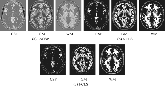
Figure 32.14 Classification of CSF, GM, and WM by their unmixed results using BEP-expanded nine bands (T1, T2, PD, cross-correlation BEP, and autocorrelation BEP) with 5% noise INU field produced by (a) LSOSP, (b) NCLS, and (c) FCLS with five substances (CSF, GM, WM, skull, and background).
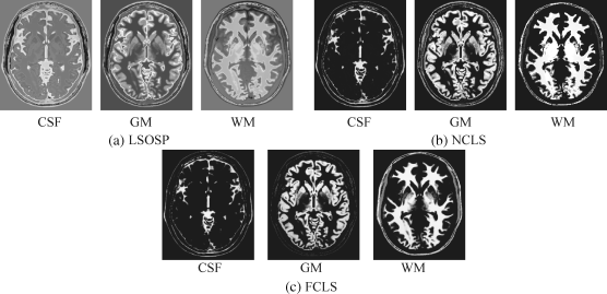
Figure 32.15 Classification of CSF, GM, and WM by their unmixed results using BEP-expanded nine bands (T1, T2, PD, cross-correlation BEP, and autocorrelation BEP) with 10% noise INU field produced by (a) LSOSP, (b) NCLS, and (c) FCLS with five substances (CSF, GM, WM, skull, and background).

Figure 32.16 Classification of CSF, GM, and WM by their unmixed results using BEP-expanded nine bands (T1, T2, PD, cross-correlation BEP, and autocorrelation BEP) with 20% noise INU field produced by (a) LSOSP, (b) NCLS, and (c) FCLS with five substances (CSF, GM, WM, skull, and background).
Comparing the results in Figures 32.13–32.16 with those in Figures 32.4–32.7, it was apparent that the BEP did improve LSMA performance in unmixing. This was mainly due to the fact that LSMA techniques were intrapixel multispectral processing techniques that took advantage of extra spectral information provided by autocorrelated and cross-correlated bands via BEP. However, it was not the case shown in Ouyang et al. (2006) where the SVM gained only little benefit from BEP because it was the interpixel-based multispectral classification technique, which was designed to take care of intervoxel spatial correlation not intraspectral correlation.
In order to further conduct a quantitative analysis on performance, the 3D ROC analysis was used for evaluation. These quantification methods show different merits in measuring classification via unmixed PVE results. The 3D ROC analysis provides a tool to evaluate the relative performance of detection probability to false alarm probability. Figures 32.17–32.20 show the 3D ROC curves along with their three corresponding 2D ROC curves for the results in Figures 32.13–32.16, where FCLS seems to be the best in most cases.
Figure 32.17 3D ROC analysis of LSOSP, NCLS, and FCLS methods operating nine expanded MR images with 0% noise INU fields.
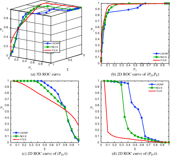
Figure 32.18 3D ROC analysis of LSOSP, NCLS, and FCLS methods operating nine expanded MR images with 5% noise INU fields.
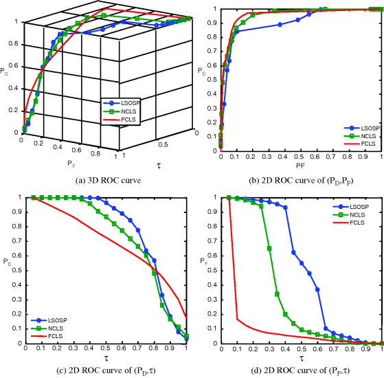
Figure 32.19 3D ROC analysis of LSOSP, NCLS, and FCLS methods operating nine expanded MR images with 10% noise INU fields.
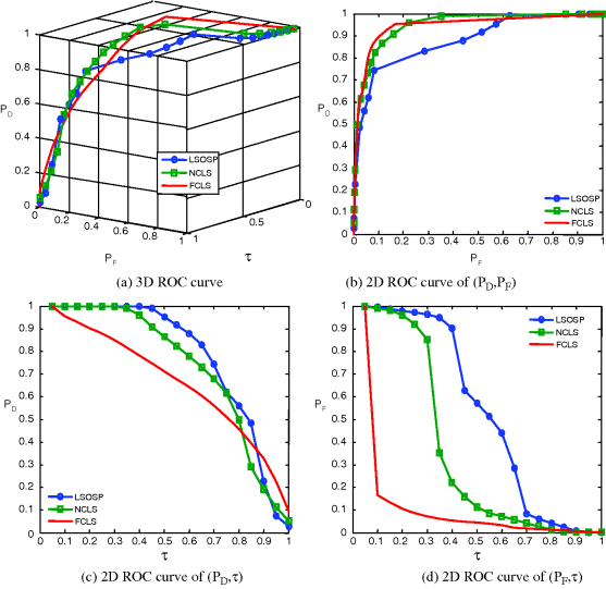
Figure 32.20 3D ROC analysis of LSOSP, NCLS, and FCLS methods operating nine expanded MR images with 20% noise INU fields.
For a further comparison, Table 32.1 also gives Az of 3D ROC curves for mean classification rates of CSF, GM, and WM produced by LSOSP, NCLS, and FCLS using three bands (original bands) in Figures 32.8–32.11 and nine bands (original plus six BEP-expanded bands) in Figures 32.17–32.20.
From Table 32.1, FCLS remained the best classifier in terms of highest Az of (PD,PF) in all scenarios except the case of 20% noise with a very small fallout. It should be noted that both the curve of (PD,τ) and the curve of (PF,τ) generally behaved oppositely. That is, the better the detector, the higher the Az of (PD,τ) and the smaller the Az of (PF,τ). So, a good detector should have a high Az of (PD,PF) with an appropriate compromise between the Az of (PD,τ) and the smaller Az of (PF,τ). By taking this into consideration, it seems that FCLS using six BEP-expanded MR images always yielded the best performance.
While the visual inspection of Figures 32.4–32.7 against 32.13–32.16 and Figures 32.8–32.11 against 32.17–32.20 provides qualitative evaluation of relative performance of LSMA with/ without BEP, another objective measure, called quantification least-squares error (QLSE) defined by (32.17), calculated the error of abundances between the estimated abundance fractions as PVE and their corresponding ground truth values. Table 32.2 gives QLSE of three-tissue (GM,WM, and CSF) classification produced by LSOSP, NCLS, and FCLS using three bands (original bands) and nine bands (original plus six BEP-expanded bands).
According to Table 32.2, the QLSE performance of LSMA techniques using BEP was worse compared to their counterparts without using BEP when no or only partial abundance constraints were imposed. However, the QLSE was significantly improved when abundance constraints were fully imposed, as shown in the last column of FCLS in Table 32.2. In addition, the upper rows produced by Experiment 32.4.1.1 in Table 32.1 gives QLSE obtained from Figures 32.3–32.6 where it is interesting to note that FCLS yielded the largest error compared to LSOSP and NCLS. However, the results were reversed as shown in the lower rows produced by Experiment 32.2 in Table 32.2 when nine expanded MR images were used including the original three MR images combined with six BEP-expanded bands (autocorrelated and cross-correlated). Nevertheless, in both experiments, the performance of NCLS was right in between.
Prior to performing kernel-based LSMA, the prior knowledge of tissue signatures (M) was obtained from the areas shown in Figure 32.3 based on provided ground truth in Figure 32.2(b) where only four tissues of interests, CSF, GM, WM, and skull were obtained by averaging the training samples of these four signatures in Figure 32.3 and the fifth signature was obtained by averaging the training samples of other signatures in Figure 32.3. Based on the study in Wong (2008), this five-signature matrix (M) usually provided best classification results. Once the signature matrix (M) was obtained, both the original 0% and 20% INU synthetic brain MR images were classified using kernel-based LSMA techniques, K-LSOSP, K-NCLS, and K-FCLS presented in Section 32.4. In addition, following a similar treatment to that carried out in Section 31.5 experiments were also conducted by combining the BEP-preprocessed MR images with LSOSP, NCLS, and FCLS and their kernel counterparts K-BEP-LSOSP, K-BEP-NCLS, and K-BEP-FCLS to see if the BEP could improve the performance. As noted earlier, only the cross-correlated band images were used since they provided sufficient spectral information for LSMA according to Wong (2008). Besides, the radial basis function (RBF) has been widely used in kernel-based methods. Hence, it was used in our test kernel-based LSMA in which case only the parameter σ needed to be appropriately determined. Since the range of the parameter σ varies with different kernel-based LSMA methods, in order to make comparable analysis, each MR image band was normalized to the range of [0,1] so that the selection of the parameter σ could be made between 0 and 1. As a result, the value of the σ was selected empirically to achieve the best possible visual classification in which case for each kernel-based LSMA method, σ = 0.1 for K-LSOSP, σ = 0.1 for K-NCLS, σ = 0.05 for K-FCLS, σ = 0.1 for K-BEP-LSOSP, σ = 0.1 for K-BEP-NCLS, and σ = 0.05 for K-BEP-FCLS. Figure 32.21 shows respectively their classification results obtained by using LSMA-unmixed abundance fractions as their PVE for the cases of 20% INU field-corrupted MR images classification. Since CSF, GM, and WM were the main tissue of interest, other classification results were not included in the figures. As mentioned earlier, same conclusions could also be drawn for both 0% INU and 20% INU noise corruption. For this reason, only the 20% INU noise-corrupted MR brain image PVE results are shown in the following.
Figure 32.21 Classification results of three main brain tissues with 20% INU field produced by (a) BEP-LSOSP, (b) BEP-NCLS, (c) BEP-FCLS, (d) K-LSOSP, (e) K-NCLS, (f) K-FCLS, (g) K-BEP-LSOSP, (h) K-BEP-NCLS, and (i) K-BEP-FCLS with five substances (CSF, GM, WM, skull, and background).

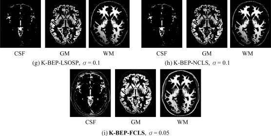
Some noteworthy observations can be made on Figure 32.21 by visual inspection. First, kernel-based approaches greatly improved their counterparts without using kernels. For example, it was easily observed by comparing Figure 32.21(a) with Figure 32.21(b) where the LSOSP approach was not able to distinguish CSF, GM, and WM tissues, but K-LSOSP was able to clearly classify these tissues. Moreover, the K-LSOSP PVE results shown in Figure 32.21(a) produced the least false positive classification. In particular, the CSF and GM PVE results showed little false positive classification.
On the other hand, K-NCLS and K-FCLS produced better PVE results by classification for the three main brain tissues shown in Figure 32.21(b) and (c) than K-LSOSP. However, they also suffered from higher false positive detection. For example, muscle tissue was misclassified into WM as presented in Figure 32.21(b) and (c), and skin/connectives were falsely classified into GM. In the case of K-BEP-LSMA results, K-BEP-LSOSP and K-BEP-NCLS methods provided better results than K-BEP-FCLS. Moreover, the INU noise corruption effect indeed showed significant impact on the methods in Figure 32.21(a) and (b). Furthermore, a great improvement could be observed from most of the kernel-based LSMA PVE results as presented in Figure 32.21(d)–(i). Nevertheless, the INU corruption effect was still visible for K-LSOSP PVE results in Figure 32.21(d), which indicated that the K-LSOSP was still sensitive to INU corruption.
Since Figure 32.2(b) provides the ground truth of brain tissues used to simulate the MR images, this allows us to conduct a quantitative analysis among various proposed LSMA-based methods, BEP-LSOSP, K-LSOSP, K-BEP-LSOSP, BEP-NCLS, K-NCLS, K-BEP-NCLS, BEP-FCLS, K-FCLS, and K-BEP-FCLS. Figure 32.22 shows 3D ROC curves (PD versus PF versus τ) along with three 2D ROC curves (PD versus PF, PD versus τ, and PF versus τ) of these methods plotted for the cases of 20% INU where (a–d), (e–h), and (i–l) are plots generated by LSOSP, NCLS, and FCLS methods, respectively. The ROC analyses of the 0% and 20% INU noise-corrupted brain MR images are again identical. Hence, only the 20% INU results are presented.
Figure 32.22 3D ROC, PD versus PF, PD versus τ, and PF versus τ curves for 20% INU noise-corrupted MR images with (a)–(d) generated by BEP-LSOSP, K-LSOSP, and K-BEP-LSOSP, (e)–(h) generated by BEP-NCLS, K-NCLS, and K-BEP-NCLS, and (i)–(l) generated by BEP-FCLS, K-FCLS, and K-BEP-FCLS.

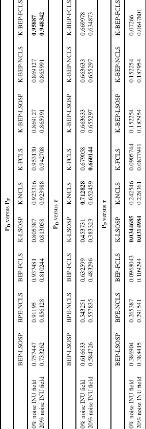
In addition to the ROC curves, the area under curve (Az) value was calculated for each of 2D ROC curves. It is worth noting that the best performance of Az for the overall detection (PD versus PF) and true positive detection (PD versus τ) is 1, while the highest false positive performance (PF versus τ) is 0. With this in mind, the resulting Az values were calculated for each method and tabulated in Table 32.3 where the bold-faced numbers represent the best performance values under each classification criterion (overall, true positive, and false positive detection). In addition, the 0% INU noise corrupted is included in this table because the benefits of kernel-based techniques can be easily observed.
As shown in Table 32.3, all the kernel-based techniques produced better overall PVE than the non-kernel-based techniques. In particular, the overall PVE based on Az under the 2D ROC curve of PD versus PF suggested that K-LSMA increased correct classification rates while also decreasing false positive detection rates. Also, based on the values of PD versus τ and PF versus τ, the K-LSMA performed better than the non-kernel-based LSMA in terms of higher true positive rate and lower false positive rate.
If the true positive rate were the main criteria of concern, K-NCLS and K-FCLS techniques would had demonstrated superior performances for 0% and 20% INU-corrupted MR images experiments. Interestingly, LSMA combining BEP with kernels improved true positive performance, but it also introduced more distortions to the MR images and thus, generally speaking, they did not outperform K-NCLS and K-FCLS. Furthermore, kernel-based techniques did not find a substantial amount of improvement in the case of 0% INU-distorted MR image experiment. But, they did significantly improve the performance for 20% INU MR PVE. This strongly suggested that kernel-based techniques could suppress noise effects when MR images are heavily corrupted by unknown noise.
In addition, according to Table 32.3, K-LSMA could improve performance by reducing false positive rate. For example, K-LSOSP yielded the lowest Az values for both cases of 0% and 20% INU-distorted MR images, while BEP-LSOSP showed the worst false positive performance. Furthermore, The K-BEP-NCLS and K-BEP-FCLS outperformed K-NCLS and K-FCLS. However, K-BEP-LSOSP did not show any advantage over K-LSOSP. Similar to true positive performance, little improvement of K-LSMA was observed over the non-kernel-based LSMA for the 0% INU MR image experiment. On the contrary, false positive rate was greatly reduced for the 20% INU-distorted MR images, which suggested that K-LSMA improved non-kernel-based LSMA in heavily noise-corrupted MR image.
Finally, as for overall performance, the values of PD versus PF in Table 32.3 suggest that K-BEP-FCLS produced the best PVE. In general, K-LSMA outperformed non-kernel-based LSMA in terms of overall performance. In addition, K-BEP-LSOSP and K-BEP-FCLS showed better PVE results than their kernel-based counterparts. However, it was not true for K-BEP-NCLS, which did not perform better than K-NCLS. Also, K-LSMA showed little advantages in the 0% INU-distorted MR image experiments, but it did improve performance significantly for 20% INU-distorted MR image experiments.
In summary, both kernel-based LSMA (i.e., K-LSOSP, K-NCLS, and K-FCLS) and kernel-BEP-based LSMA (i.e., K-BEP-LSOSP, K-BEP-NCLS, and K-BEP-FCLS) significantly outperformed non-kernel-based LSMA (i.e., LSOSP, NCLS, and FCLS). Moreover, according to the above 3D analysis, the kernel-based LSMA showed great improvement in the true positive rate, false positive rate, and overall performance over non-kernel-based LSMA. If the kernel-based LSMA were further extended by combining the BEP, only slight improvement was observed. However, without using kernels, the BEP did indeed help LSMA improve performance significantly as reported in Wong (2008). Finally, all the experiments conducted in this section demonstrated that the greatest advantage of the K-LSMA is the ability of using kernels in improving performance when the MR image is corrupted by high INU noise.
This benefit suggested that the KLSMA can be a promising technique in applications of MR image analysis.
Table 32.1 Az of 3D ROC curves for mean classification rates of CSF, GM, and WM for three-tissue (GM, WM, and CSF) classification of LSOSP, NCLS, and FCLS using three bands (original bands), six bands (original plus three BEP-expanded bands), and nine bands (original plus six BEP-expanded bands).
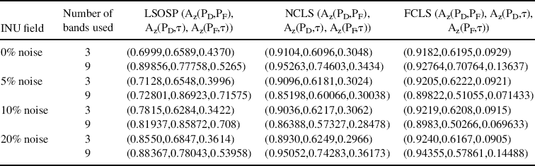
Table 32.2 Quantification least-squares error (QLSE) of abundance estimated of CSF, GM, and WM for three-tissue (GM, WM, and CSF) classification of LSOSP, NCLS, and FCLS using three bands (original bands) and nine bands (original plus six BEP-expanded bands)
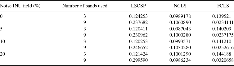
Table 32.3 Area under curve (AZ) calculated under PD versus PF, PD versus τ, and PF versus τ curves of BEP-LSMA, K-LSMA, and K-BEP-LSMA.