19.7 Experiments
All the exploitation-based spectral/spatial compression techniques presented in previous sections are carried out in two stages, that is, VD-determined spectral compression in the first stage followed by either JPEG2000 Multicomponent or 3D-SPIHT spatial compression in the second stage. For the spatial compression, a variable bit-rate lossy compression technique is used in both JPEG2000 Multicomponent and 3D-SPIHT. Since PCA and ICA transforms generate real numbers, we have rounded these numbers to 16 bits in the implementation of spectral/spatial compression techniques. Also, PCA and ICA are data dependent transforms; thus, their component projection vectors need to be stored and/or transmitted in order to perform reconstruction of the data. This factor is considered as an overhead and further included in calculation of compression ratio.
The compression ratios are chosen to be 20, 40, 60, and 100 because little difference is noted in the detection/quantification performance for compression ratios lower than 20. This implies that for very low compression ratios (<10) 3D-cube compression alone and spectral/spatial based compression can successfully preserve the subpixel and mixed pixel information. Such subtle difference can be only observed when the data are compressed with high compression ratios (>40). In order to address the issues of subpixels and mixed pixels, two examples are custom-designed to illustrate and demonstrate the superiority of spectral/spatial compression over 3D-cube compression in terms of preserving subpixel and mixed pixel spectral information.
19.7.1 Synthetic Image Experiments
The first example was designed to investigate the issue of subpixel quantification of subtle targets (weak signals) embedded in a single background, in which case both PCA- and ICA-based compression techniques worked well compared to 3D-cube compression alone. As a matter of fact, it was demonstrated in Ramakrishna et al. (2006) that for subpixel detection of subtle targets (weak signals) over a single background ICA-based compression techniques worked the best. The second example was designed to investigate the issue of subpixel and mixed pixel quantification of strong targets (strong signals) embedded in multiple backgrounds, in which case ICA did not work as expected and the best results were obtained by using PCA-based compression.
Example 19.1
(Single Background)
The synthetic image to be used for our experiments in this example is shown in Figure 19.14 that is similar to the real HYDICE scene in Figure 1.15(a) and has the same size of 64 × 64 pixel vectors.
Figure 19.14 Sixteen panels implanted in a single background.

The background in the synthetic image is simulated by p1 panel signature from the image scene in Figure 1.17 with an added Gaussian noise to achieve signal-to-noise ratio (SNR) 30:1. There are 16 panels located at the center and arranged in four rows with four panels in each row. The four panels in the ith row and the first column composed of single pure pixels, denoted by pi,11pi,12, pi,21, and pi,22 pixel vectors simulated by pi from Figure 1.16 for ![]() , respectively. The single panel in the ith row and the second column is a single-pixel panel, denoted by pi2 simulated by pi with abundance 75%. The single panel in the ith row and the third column are single-pixel panel, denoted by pi3 simulated by pi with abundance 50%. The single panel in the ith row and the fourth column is a single-pixel panel, denoted by pi4 simulated by pi with abundance 25%. Figure 19.14 shows a synthetic image obtained by implanting the 16 simulated panels in the background image where their corresponding background pixels are removed to accommodate the panel pixels. It should be noted that the noise background in Figure 19.14 has been visually suppressed because of high-intensity gray level values of panel pixels. Table 19.1 shows the subpixel abundance fractions of the panels in five rows for the different compression techniques over different compression ratios.
, respectively. The single panel in the ith row and the second column is a single-pixel panel, denoted by pi2 simulated by pi with abundance 75%. The single panel in the ith row and the third column are single-pixel panel, denoted by pi3 simulated by pi with abundance 50%. The single panel in the ith row and the fourth column is a single-pixel panel, denoted by pi4 simulated by pi with abundance 25%. Figure 19.14 shows a synthetic image obtained by implanting the 16 simulated panels in the background image where their corresponding background pixels are removed to accommodate the panel pixels. It should be noted that the noise background in Figure 19.14 has been visually suppressed because of high-intensity gray level values of panel pixels. Table 19.1 shows the subpixel abundance fractions of the panels in five rows for the different compression techniques over different compression ratios.
Table 19.1 Abundance fractions (%) of the panels in five rows.

Clearly, the synthetic image in Figure 19.14 is composed of five different classes including four panel signatures p2, p3, p4, p5 and one background class p1. To verify this number, the virtual dimensionality (VD) in Chapter 5 was used to determine the number of spectrally distinct signatures present in this synthetic image by the Harsanyi–Farrand–Chang (HFC) method developed in Harsanyi et al. (1994). It was 5 across all false alarm probabilities, which was exactly the same number of spectrally distinct signatures according to the ground truth. The VD-estimated value, nVD = 5 provided the necessary knowledge about how many components needed to be retained when dimensionality reduction was performed, provided that each component can be used to accommodate one distinct signature. In the case of Figure 19.14, the number of components required after dimensionality reduction was 5.
In order to demonstrate the issues of subpixels and mixed pixels caused by lossy data compression, the unsupervised fully constrained least squares (UFCLS) developed by Heinz and Chang (2001) in Chapter 8 was used to unmix the abundance fractions of all subpixels and mixed pixels in Figure 19.14. Since the results obtained for panels in each of five rows were very similar, Table 19.2 only tabulates the abundance fractions of the second, third, and the fourth single pixel panels in the first row of the synthetic image obtained by 3D-cube compression and spectral/3D compression techniques. From Table 19.2 the performance of 3D SPIHT seemed acceptable for CR = 20, 40, but its performance for CR = 60 and 100 was poor. The performance of JPEG 2000 Multicomponent was very poor in all the cases. On the other hand, the spectral/3D compression techniques except ICA/JPEG2000 Multicomponent performed well under all compression ratios where the crucial subpixel and mixed pixel information was well preserved through spectral compression with the spatial compression only causing very little or no deterioration of subpixel and mixed pixel information. In fact, the compression ratios did not seem to have impact on their compression performance. However, despite the fact that ICA/JPEG2000 Multicomponent did not perform as well as the other three spectral/3D compression techniques did, it is interesting to note that its inverse counterpart, IICA/JPEG2000 Multicomponent, did perform very well. This implies that ICA/JPEG2000 Multicomponent tended to over-unmix the abundance fractions by over- suppressing the background. In addition, the use of inverse ICA-reconstructed images seemed to be able to correct the issue of over-unmixed abundance fractions resulting from compression.
Table 19.2 Abundance fractions (%) for the second, third, and the fourth single pixel panels in the first row for different compression ratios.

Table 19.3 also calculates SNR and MSE for the two spectral/3D compression techniques, IPCA/JPEG2000 Multicomponent and IICA spectral/ JPEG2000 Multicomponent along with 3D-SPIHT, JPEG2000 Multicomponent for CR = 100, 60, 40, and 20.
Table 19.3 SNR and MSE values for different compression techniques.

It should be noted that in order to make fair compression, no MSE and SNR were calculated for PCA/JPEG2000 Multicomponent and ICA/JPEG2000 Multicomponent because they were performed in reduced dimensions. As shown in Table 19.3, IICA yielded the worst MSE and SNR, but its performance was among the best in terms of subpixel quantification according to Table 19.2. The reason for this was because the image background was largely suppressed by ICA and much of background information was lost in the image reconstruction by IICA.
Example 19.2
(Multiple Backgrounds)
Example 19.1 demonstrated that JPEG2000 Multicomponent did not perform well for all compression ratios, but 3D-SPIHT did reasonably well in some cases such as CR = 20, 40. In the following example, we will further show that both 3D-SPIHT and JPEG2000 Multicomponent fail to address the issues of subpixels and mixed pixels. In doing so, the synthetic image shown in Figure 19.15 was custom designed to address the inability of 3D compression such as 3D-SPIHT and JPEG2000 Multicomponent in preserving quantitative information provided by subpixels and mixed pixels.
Figure 19.15 Synthetic imagery for Example 2 showing the four quadrants and the subpixel and mixed pixel implanted in each.
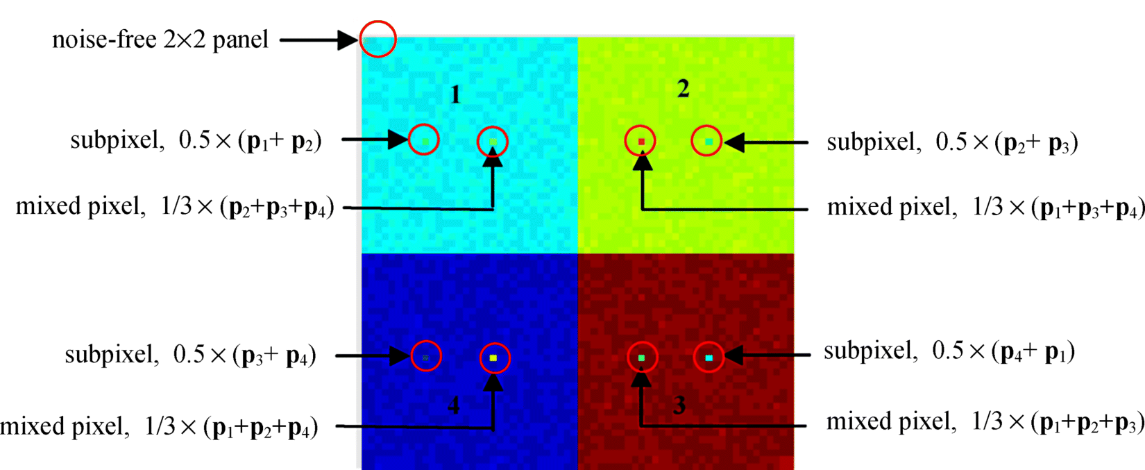
The image in Figure 19.15 was similar to the one used in Figure 19.14 in Example 19.1 with the same image background the same size of 64 × 64 pixel vectors, but had different inserted panel pixels indicated in Figure 19.15. Specifically, the image is divided into four quarters, each of which had its own background composed of a different panel signature where the background in each of the four quarters was simulated by one of p1, p2, p3, p4, respectively, with an added Gaussian noise to achieve signal-to-noise ratio (SNR) 30:1. The background pixels in a 2 × 2 square panel marked by a circle at the upper left corner had no noise added. In each of these quarters a subpixel and a mixed pixel with specific abundance fractions were implanted by replacing the original pixels. There were two single one-pixel panels implanted in each background marked by circles in Figure 19.15. The difference between images in Figures 19.14 and 19.15 is that the image background in Figure 19.15 was made up of four different signatures instead of a single image background signature in Figure 19.14. Table 19.4 tabulates the abundance fractions of subpixels and mixed pixels in the four quadrant simulated by four panel spectral signatures p1, p2, p3, p4 from Figure 1.16.
Table 19.4 Abundance fractions (%) of the implanted panels in each of the four quadrants.

It should be noted that a subpixel target simulated was defined as a target with fractional abundance embedded in a background (B). For example, in the first quadrant the first panel contained a subpixel with target signature p2 of fractional abundance 50% with the background signature p1 of 50% and the second panel is a mixed pixel with the three signatures p2, p3, and p4 sharing the same fractional abundance 1/3.
It is worth noting that this example was particularly designed so that ICA would not be applicable because the image backgrounds in the four quadrants were simulated by different Gaussian noises, in which case ICA could not unmix the simulated four Gaussian noises.
Once again, VD was used to estimate the number of spectrally distinct signatures for this scene, which was 4 across all false alarm probabilities PF = 10−1, 10−2, 10−3, and 10−4. This was different from the value of 5 estimated by VD for the scene in Figure 19.14. The value of 4 estimated by VD was exactly the same number of panel signatures. p1, p2, p3, p4 used to simulate the image in Figure 19.15 and the original dimensionality was reduced to 4, i.e., q = 4.
Now, UFCLS was used to unmix the abundance fractions of all subpixels and mixed pixels. Table 19.5 tabulates UFCLS-unmixed abundance fractions for the subpixel and mixed pixel panels.
Table 19.5 Abundances fractions (%) for the subpixel and the mixed pixel panels in the first quadrant using UFCLS unmixing for different compression ratios.

Apparently, the compression performance of 3D SPIHT and JPEG2000 Multicomponent was very poor for CR = 100 and 60 and was only improved slightly even for CR = 40 and 20 in quantification of subpixels and mixed pixels, particularly, their performance in mixed pixel quantification with all compression ratios. By contrast, IPCA-JPEG2000 Multicomponent and PCA-JPEG2000 with all compression ratios performed consistently better for both subpixel and mixed pixel quantification. The experimental results in this example were also very similar to those in Example 19.1.
Table 19.6 also calculates SNR and MSE for the three compression techniques, 3D-SPIHT, JPEG2000 Multicomponent and IPCA/JPEG2000 Multicomponent with CR = 100, 60, 40, and 20 where all the three produced similar SNRs and MSEs.
Table 19.6 SNR and MSE values for different compression techniques.

According to Tables 19.5 and 19.6 IPCA/JPEG2000 Multicomponent performed very well in both quantification of subpixels and mixed pixels with very close SNR/MSE. Similar conclusions drawn from Examples 19.1 and 19.2 were also observed in Ramakishna (2004), Ramakishna et al. (2005), and Ramakishna et al. (2006). All these experiments conducted above as well as those in in Ramakishna (2004), Ramakishna et al. (2005), and Ramakishna et al. (2006) demonstrated an important fact that using SNR and MSE as compression measures was inappropriate to address the issues of subpixels and mixed pixels when compression ratio was high, that is, greater than 20. This implies that SNR and MSE could not be blindly applied to hyperspectral data compression without precaution.
19.7.2 Real Image Experiments
In this section, similar experiments conducted for the synthetic images in Section 19.6.1 were also performed for the real image scene in Figure 1.16. The CEM discussed in Chapter 2 and UFCLS in Chapter 8 were also used to investigate the issues of subpixel detection and mixed pixel classification/quantification respectively for the same six compression techniques used in Section IV, 3D-SPIHT, JPEG2000Multicomponent, PCA/JPEG2000 Multicomponent, ICA/JPEG2000 Multicomponent, IPCA/JPEG2000 Multicomponent, and IICA/JPEG2000 Multicomponent for performance evaluation. The VD estimated for this scene was 9 according to experiments conducted in Chapter 5.
Example 19.3
(Subpixel Panel Detection)
The CEM was implemented on the 15 panels in Figure 1.15(b), particularly the five subpixel panels, p13, p23, p33, p43, p53 in the third column to show the effect of lossy compression on target detection where the p1, p2, p3, p4, p5 in Figure 1.16 were used as desired target signatures. The results of the CEM implemented on the original uncompressed image are shown in Figure 19.16.
Figure 19.16 15-panel detection results by applying CEM on the original image scene in Figure 1.16(a).

Since similar results were obtained for panels in all the five rows, Figures 19.17–19.22 only show results obtained for detection of panels for the fifth row by applying CEM to six compressed images resulting from 3D-SPIHT, JPEG2000 Multicomponent, PCA/JPEG2000 Multicomponent, ICA/JPEG2000 Multicomponent, IPCA/JPEG2000 Multicomponent, IICA/JPEG2000 Multicomponent. This is because the detection of the panels in the fifth row is challenging due to the panels in rows 4 and 5 made by the same panel materials with two different paints. As a result, CEM detected panels in both rows 4 and 5 if either p4 or p5 was used as a desired signature. This was also true for CEM in detection of panels in the second and third rows.
Figure 19.17 Detection of panels in the fifth row by produced by applying CEM to 3D-SPIHT compressed images.

Figure 19.18 Detection of panels in the fifth row by produced by applying CEM to JPEG2000 Multicomponent-compressed images.

Figure 19.19 Detection of panels in the fifth row by produced by applying CEM to PCA/JPEG2000 Multicomponent compressed images.

Figure 19.20 Detection of panels in fifth row by produced by applying CEM to ICA/JPEG2000 Multicomponent compressed images.

Figure 19.21 Detection of panels in the fifth row by produced by applying CEM to IPCA/JPEG2000 Multicomponent compressed images.

Figure 19.22 Detection of panels in the fifth row by produced by applying CEM to IICA/JPEG2000 Multicomponent compressed images.

Comparing all the detection results in Figures 19.17–19.22 against that in Figure 19.16, the best results were those produced by ICA/JPEG2000 Multicomponent and IICA/JPEG2000 Multicomponent where PCA-based/3D compression was among the worst and 3D compression came in between but did not perform well either.
Example 19.4
(Mixed Pixel Panel Quantification)
The experiments conducted in Example 19.3 were designed to investigate the issue of subpixel target detection where only desired target knowledge was required. The following example was conducted to demonstrate the ineffectiveness of 3D lossy compression on mixed pixel panel classification and quantification with UFCLS used to perform unmixing for quantification of the 15 panels. In this case, the target knowledge must be known prior to UFCLS. It was demonstrated in Heinz and Chang (2001) and Chang (2003a) that 34 target pixels could be generated in an unsupervised manner and provided sufficient target information for UFCLS to perform well. Once again, due to similar results that could be obtained for all the 15 panel pixels as Example 19.3 did, Table 19.7 only tabulates UFCLS-unmixed abundance fractions (%) of three panels in the fifth row where the panel in the first column is a two-pixel panel, denoted by p511 and p512, the panel pixel p52 in the second column and the subpanel pixel by p53 in the third column. The six lossy compression techniques 3D-SPIHT, JPEG2000 Multicomponent, PCA/JPEG2000 Multicomponent and ICA /JPEG2000 Multicomponent, IPCA/JPEG2000 Multicomponent, IICA-JPEG2000 Multicomponent were evaluated for CR = 100, 60, 40, and 20.
Table 19.7 Abundance fractions (%) of the mixed pixel panels of the fifth row.

From this table we can see that ICA-based spectral/spatial compression techniques clearly outperformed the other compression techniques. More interestingly, the compression ratios had little effect on the unmixed abundance fractions of PCA/spatial and ICA/spatial compression techniques, while the accuracy of the unmixed abundance fractions of 3D-SPIHT and 3D-multicomponent JPEG2000 was gradually increased with compression ratios. Finally, Table 19.8 also tabulates SNR and MSE for the four compression techniques, 3D-SPIHT, JPEG2000 Multicomponent, IPCA/JPEG2000 Multicomponent, and IICA/JPEG2000 Multicomponent with CR = 100, 60, 40, and 20 where IICA yielded the worst MSE and SNR, but produced the best detection performance in Figure 19.22 among the four techniques.
Table 19.8 SNR and MSE for different compression techniques.

The above experiments provided further evidence that MSE and SNR were indeed not appropriate criteria to be used for compression to address issues of subpixels and mixed pixels for hyperspectral image compression.
One particular comment is noteworthy. According to all the conducted experiments, the improvement on compression performance of 3D compression techniques was closely related and proportional to an increase in SNR, decrease of MSE as well as decrease of compression ratio. That is, the better performance the 3D compression; the higher the SNR, the smaller the MSE and the lower the compression ratio. This observation explains the reason why researchers in data compression community have focused their attention on criteria of SNR and MSE. Unfortunately, this common sense is no longer true for hyperspectral data compression when compression ratio is high as just demonstrated in the above four examples. This is because SNR and MSE have very little impact on subpixel and mixed pixel analyses such as subpixel detection and mixed pixel quantification in these cases. In other words, in order for a hyperspectral data compression to be effective, exploitation applications are the key to its success. Blinding using SNR and MSE as compression criteria may mislead results in hyperspectral data interpretation and analysis.
Example 19.5
(Mixed Component Analysis for Spectral/Spatial Compression)
The HYDICE 15-panel scene was once again used for experiments to demonstrate the utility of mixed- component analysis for spectral/spatial compression systems in Figure 19.9. Five scenarios of mixed PCA/ICA transform with (m = 9, n = 0) (i.e., PCA), (m = 0, n = 9) (i.e., ICA), (m = 1, n = 8), and (m = 2, n = 7) were investigated for applications in mixed pixel classification/quantification with UFCLS used to evaluate their performance on compressed and decompressed domains. These experiments were considered in Chai et al. (2007) to investigate mixed PCA/ICA component analysis for hyperspectral imagery. In this case, the estimated value of VD was q = 9 and the number of classes to be classified was also set to p = q = 9. Like Experiment 19.6.4, 34 target pixels were used to provide prior knowledge for mixed pixel classification/quantification. Therefore, UFCLS was applied to the original HYDICE image with p set to 34 to perform unmixing. Figure 19.23 shows only five images that are used to unmix the 15 panels. These mixed pixel classification results were used as a benchmark for studying the following spectral/spatial compression experiments conducted by mixed component analysis.
Figure 19.23 15-panel classification by UFCLS on the original image cube.

It should be noted that since the panels in rows 2 and 3 are made the same material with different paints, the detection of panels in row 2 might also detect panels in row 3 and vice versa. Similarly, it is also true for detection for the panels in rows 4 and 5.
Experiment 19.1
(Scenario 1: PCA, (m = 9, n = 0))
In this experiment, mixed PCA/ICA transform was reduced to the standard PCA transform. Figure 19.24 shows the nine PCA-generated PCs. Figures 19.25 and 19.26 show the results unmixed by UFCLS for the 15 panels using nine PCs compressed and decompressed image cubes, respectively.
Figure 19.24 Nine principal components.

Figure 19.25 Classification by UFCLS using nine PCs in Figure 19.24.

Figure 19.26 15-panel classification by UFCLS on PCA-decompressed image cube obtained by using nine PCs in Figure 19.24.

As demonstrated in Figures 19.25 and 19.26, UFCLS performed very poorly in unmixing the 15 panels in the scene. Comparing the results in Figures 19.25 and 19.26 against that in Figure 19.23 PCA-based spectral/spatial compression failed to capture subtle details of the 15 panels. This was primarily due to the fact that PCA-based spectral compression was a second-order statistics-based transform that largely characterizes background information in Figures 19.25 and 19.26, but not panel information that is generally preserved by high-order statistics as demonstrated in the following example. As also demonstrated in Figures 19.25 and 19.26, the results produced by using the nine PC-decompressed image cubes only show little improvement on panel detection and classification. This implied that the decompressed image cube reconstructed from the nine PCs seemed provided no significant advantage in target detection and mixed pixel classification.
Experiment 19.2
(Scenario 2: ICA, (m = 0, n = 9))
As a complete opposite of Scenario 1 in Experiment 19.1 of Example 19.5, this experiment considered another scenario, called Scenario 2 where all nine components used for mixed pixel classification were nine ICs shown in Figure 19.27 obtained from the FastICA using the ATGP-generated initial projection vector.
Evidently, the nine ICs in Figure 19.27 already extracted all the 15 panels, while the background information preserved in Figure 19.24 seemed not shown in these nine ICs. Figures 19.28 and 19.29 show the results produced by UFCLS in unmixing of the 15 panels using nine ICs compressed and decompressed image cubes respectively where UFCLS performed using ICA better than using PCA in Figures 19.25 and 19.26 in terms of panel target detection.
Figure 19.27 Nine independent components.

Figure 19.28 Classification by UFCLS using nine ICs in Figure 19.27.

Figure 19.29 Classification by UFCLS using ICA-decompressed image cube obtained by using nine ICs in Figure 19.27.

Experiment 19.3
(Scenario 3: (m = 1, n = 8)-PCA/ICA transform)
Experiments 19.1 and 19.2 of Example 19.5 demonstrated advantages and disadvantages of PCA or ICA transform used for compression. This experiment investigated a scenario called Scenario 3 to see how much gain can be obtained by the proposed mixed (m,n) PCA/ICA transform.
In order to see the performance of mixed (1,8)-PCA/ICA transform in mixed pixel classification, Figures 19.30 and 19.31 show the 15-panel unmixed results by UFCLS using the (1,8) mixed component-compressed and decompressed image cubes, respectively.
Figure 19.30 Classification by UFCLS using nine mixed components.

Figure 19.31 Classification by UFCLS on the (1,8)-PCA/ICA-decompressed image cube obtained by using nine mixed components.

The results obtained in Figure 19.30 by using the (1,8) mixed component-compressed image cube seemed slightly better than those obtained in Figure 19.31 by using the (1,8) mixed component-decompressed image cube in terms of classification of 15 panels, particularly, panels in rows 2 and 3. But results shown in Figure 19.31 were closer to UFCLS results obtained based on the original image cube shown in Figure 19.23. In addition, they also extracted more background classes than that in Figure 19.30.
Experiment 19.4
(Scenario 4: (m = 2, n = 7)-PCA/ICA transform)
This experiment further investigated another scenario, called Scenario 4 to see if a further improvement can be gained by increasing one PC to 2 PCs while reducing eight ICs to seven ICs operated by a mixed (2,7) PCA/ICA transform. Figures 19.32 and 19.33 show the 15-panel unmixed results by UFCLS using the (2,7) mixed component-compressed and (2,7) mixed component-decompressed image cubes, respectively, where UFCLS performed poorly in unmixing the 15 panels in both cases.
Figure 19.32 Classification by UFCLS using nine mixed components.

Figure 19.33 Classification by UFCLS on PCA/ICA-decompressed image cube obtained by using nine mixed components.

This experiment further demonstrated that adding one more PC could only do more harm than good for UFCLS-mixed pixel classification. This is because the first PC was sufficiently enough to capture second-order statistics and adding a second PC did not provide useful information in terms of panel detection and classification, but rather obscured the panel information.
Finally, the LSEs were calculated for four scenarios conducted in the above four experiments using mixed (m,n) PCA/ICA transforms with (m,n) = (9,0), (0,9), (1,8), and (2,7). Their LSE results are tabulated in Table 19.9.
Table 19.9 LSEs calculated for Experiments 19.1–19.4.

As clearly shown in Table 19.8, LSE was increased as more PCs were replaced by ICs where the smallest and largest LSEs were produced by (9,0)-PCA and (0.9)-ICA, respectively. However, the worst performance in mixed pixel classification came from the (9,0)-PCA and (2,7)-PCA/ICA, which yielded the smaller LSEs compared to (0,9)-ICA and (1,8)-PCA/ICA that performed significantly better in the 15-panel classification but produced larger LSEs. This evidence demonstrated that a smaller LSE did not necessarily produce better performance in mixed pixel classification. This further suggested that the LSE might not be an appropriate measure for hyperspectral data compression.
Experiment 19.5
(Mixed Pixel Quantification)
The above four experiments were evaluated by visual assessment qualitatively. It is very difficult to see how a mixed (m,n)-PCA/ICA transform performed quantitatively. In doing so, we conducted this experiment to evaluate the performance of a mixed (m,n)-PCA/ICA transform in mixed pixel quantification for the 15 panels in Figure 2. According to the results obtained by the four scenarios only Scenarios 2 and 3 successfully unmixed 15 panels in terms of classification, so only the results produced by (0,9)-PCA/ICA transform and (1,8)- PCA/ICA transform were used for mixed pixel quantification analysis. Table 19.10 tabulates their abundance quantification of the 15 panels obtained in Figures 19.28 and 19.29 and Figures 19.30 and 19.31, respectively, where the results for abundance quantification of the 15 panels obtained by applying UFCLS to the original image cube in Figure 19.23 are also included for benchmark comparison.
Table 19.10 Abundance quantification by UFCLS using mixed (m, n)-PCA/ICA spectral/spatial compression.
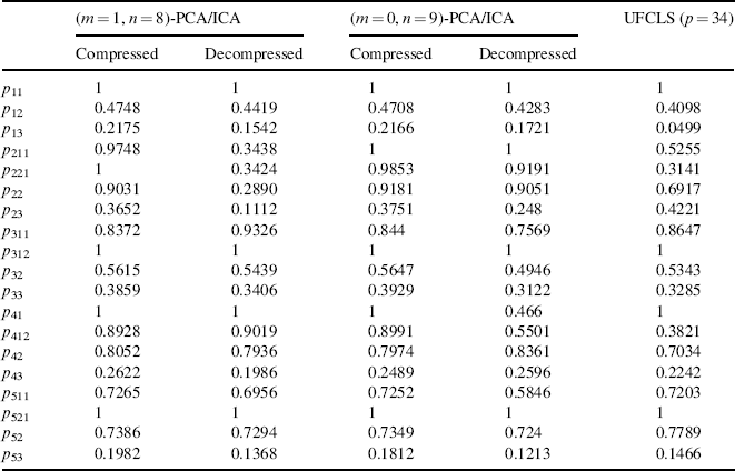
As noted in Table 19.10, the subpixel panels, p13, p23, p33, p43, and p53 in Figure 1.16(b) have the size of 1 m × 1 m smaller than the 1.56 m × 1.56 m-spatial resolution. It indicates that the size of these five subpixel panels is approximately ![]() that is equivalent to saying that the abundance fractions of these three subpixels present in a single pixel are close to 0.41,091. With this interpretation, Table 19.10 shows that both mixed (1,8)-PCA/ICA transform performed slightly better than mixed (0,9)-PCA/ICA transform in the 15-panel abundance quantification with UFCLS results obtained on the reconstruction image based on (1,8)-PCA/ICA to have the closest results to UFCLS results produced using the original image cube.
that is equivalent to saying that the abundance fractions of these three subpixels present in a single pixel are close to 0.41,091. With this interpretation, Table 19.10 shows that both mixed (1,8)-PCA/ICA transform performed slightly better than mixed (0,9)-PCA/ICA transform in the 15-panel abundance quantification with UFCLS results obtained on the reconstruction image based on (1,8)-PCA/ICA to have the closest results to UFCLS results produced using the original image cube.
One remark is noteworthy. VD = 9 used in the above experiments was only an estimate and not necessarily to be exact. According to our extensive experiments on the HYDICE 15-panel scene in Figure 1.16 for dimensionality reduction, VD = 9 was appropriate. However, since the value estimated by VD was fixed, VD = 9 used for dimensionality reduction may not be appropriate for other applications such as band selection (Chang and Wang, 2006). This is because different applications require different false alarm probabilities. So, we can always make the estimate of VD variable by varying false alarm probability at different thresholding levels. In order to make VD versatile, varying the false alarm probability can adapt various applications. Keeping this in mind, VD = 9 may be effective for dimensionality reduction, but it may not imply that it is appropriate for data compression because using ICA alone may not preserve background information and using PCA alone may miss information of small objects. Of course, if the value of p is sufficiently large, PCA and ICA can perform well. However, for a smaller value of p, neither could work well as demonstrated by our experiments. In this case, our proposed mixed PCA/ICA transform could still work well for the same value of p. This provides the evidence that mixed PCA/ICA transform has advantages over PCA and ICA by retaining strengths of PCA and ICA.
Experiment 19.6
(Mixed Pixel Panel Quantification)
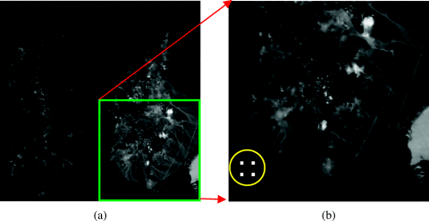
Since all similar experiments conducted for HYDICE data can be also applied to this AVIRIS Cuprite data in Figure 1.12, only mixed pixel quantification was studied for quantitative analysis for illustration to demonstrate that the proposed mixed PCA/ICA was a general approach that also worked for any hyperspectral data. In order to simplify our experiment, only a quarter size of the image at right bottom corner in Figure 19.34(a) was selected for study and is shown in Figure 19.34(a) and (b) with four 3 × 3 simulated panels implanted at the left bottom corner in Figure 19.34(b) in such a way that the implanted panel pixels replaced their corresponding real image pixels. In other words, the image scenes in Figures 1.12(b) and 19.34(b) are identical except that there are 36 simulated (nine pixels for each panel) pixels implanted in Figure 19.34(b) to replace the original 36 real image pixels in Figure 1.12(b). These four panels, denoted by pij for i = 1,2 and j = 1,2, were simulated in accordance with composition of signatures specified in Table 19.11 where row and column indices are indicated by i and j, and the BKG was specified by the signatures of the real image pixels in the scene that were replaced by their corresponding implanted pixels. For example, all nine pixels in panel p12 were simulated by 50% Calcite and 50% background (BKG) signature specified by their replaced real image pixels. So, all of these nine simulated panel pixels contained 50% Calcite, but 50% different BKG signatures.
Figure 19.34 Spatial locations of four implanted panels.
Two benefits can be gained from our designed experiments. One is that the data are available on website so that whoever is interested in our proposed method can repeat what we did in the experiments to compare their new algorithms. The other benefit is that all parameters used to simulate the panels were fully controlled so that performance analysis was conducted impartially and objectively. VD estimated for the image scene in Figure 15(b) was 10 with the false alarm probability set by PF = 10−3. By virtue of VD = 10 and the 36 panel pixels simulated in Table 19.11 a detailed analysis for their quantifications can be conducted by UFCLS using PCA only, ICA only, and Mixed PCA/ICA transforms. Interestingly, the quantitative unmixed results obtained by UFCLS for panels in row 1 and row 2 were quite different and were analyzed as follows.
Figure 19.35 Graphical representation of Table 19.12 for visual assessment.

Figure 19.36 Graphical representation of Table 19.13 for visual assessment.
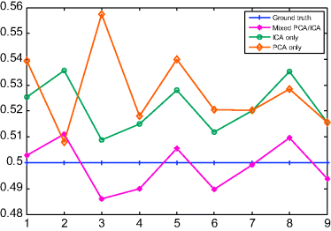
Table 19.11 Compositions of four simulated panels.
| Pixel | Signatures | Composition |
| Nine pixels in p11 | Calcite | 100% Calcite + 0% BKG |
| Nine pixels in p12 | Calcite, BKG | 50% Calcite + 50% BKG |
| Nine pixels in p21 | Kaolinite | 100% Kaolinite + 0% BKG |
| Nine pixels in p22 | Kaolinite, BKG | 50% Kaolinite + 50% BKG |
Table 19.12 UFCLS estimated abundance fractions of calcite contained in nine panel pixels in p12 in row 1.

Table 19.13 UFCLS-estimated abundance fractions of kaolinite contained in the nine panel pixels in p22 in row 2.

