
20.6 Experiments for PSDP
This section conducts real image experiments to substantiate the utility of PSDP in a wide range of data exploitation. Since PSDP is preprocessing and very crucial to subsequent data analysis, its effectiveness can only be demonstrated through applications.
20.6.1 Endmember Extraction
A first immediate application of PSDP is endmember extraction that generally requires data dimensionality reduction. The data used for experiments for endmember extraction was the Cuprite data in Figure 1.12(a), where IN-FINDR was used as an endmember extraction algorithm to extract the five mineral signatures, A, B, C, K, and M, of major interest in the scene. Because of too many combinations of PI/PI that can be used for PSDP for an illustrative purpose, Figure 20.1(a) and (b) only plots results of extracting the mineral signatures by N-FINDR using PSDP with PI/PI = skewness/skewness and variance/kurtosis, respectively, where the x-axis is the number of prioritized dimensions and the y-axis is the endmembers extracted by N-FINDR. When the number of extracted endmembers was less than five, we need to know which endmembers were extracted in which case the extracted endmembers were also specified for reference. For example, in Figure 20.1(a) when PSDP was implemented by a pair of PIs, PI = skewness/PI = skewness for q = 4, 5, the number of extracted endmembers was 3 with extracted endmembers being identified as A, B, M. However, as q was increased to 6, the number of extracted endmembers was still 3. But this time, three extracted signatures B, C, K had only one signature B in common. This implies that if q was too small, the results were not stable even though the same number of endmembers was extracted by different values of q. Interestingly, when q = 10 all the five mineral signatures were successfully extracted by IN-FINDR which failed again at q = 16 in which case it missed the signature A until it reached q = 18 where the stability was also reached. In other words, after q went beyond 18 all the five endmembers were extracted. This shows that nVD = 22 provided a good estimate for q.
Figure 20.1 Endmembers extracted by IN-FINDR as PSDP implemented.
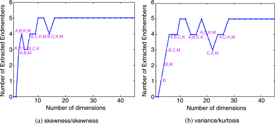
However, if the commonly used PCA was used to perform DR in which case PI = variance and the PICs (in this case, PICs are reduced to PCs) were ranked by another PI = kurtosis, Figure 20.1(b) shows the results of endmember extraction versus the number of prioritized dimensions where the stability reached after q = 28. A surprising coincidence was observed by comparing Figure 20.1(a) and (b), where IN-FINDR could extract all five mineral signatures for both cases when q = 10–12 and 18. This simple example demonstrated that an appropriate value of q must be determined by the PI used to generate PICs and another PI used to rank the order of PICs. None of DR techniques can claim to perform better than another unless criteria for DP are specified.
20.6.2 Land Cover/Use Classification
As another example, the Purdue Indiana Indian Pine Test Site in Figure 1.13 was also used for experiments. This particular scene is probably one of most studied test sites in hyperspectral data exploitation for land cover/use classification. Because of its low 20 m spatial resolution, most data sample vectors in this scene are heavily mixed because of large spectral variations of class signatures. As a consequence, spectral unmixing did not work effectively for this scene because finding an appropriate set of creditable signatures to unmix data sample vectors was very challenging, if not impossible. Instead, the maximum likelihood classifier (MLC) has widely been used for this particular scene in the literature. Here, MLC was also used for this purpose. Assume that Sj represents a training sample set selected for the jth class and ![]() is the entire training set. The mean and sample covariance matrix of
is the entire training set. The mean and sample covariance matrix of ![]() are calculated by
are calculated by ![]() and
and
where |A| is defined as the number of elements in the set A. Furthermore, let the mean of the jth class calculated from Sj be given by ![]() . Then, for each data sample vector r, the MLC denoted by δMLC(r) used for the following experiments is defined by
. Then, for each data sample vector r, the MLC denoted by δMLC(r) used for the following experiments is defined by
that assigns the data sample vector r to the class j∗ with the j∗ found by
It should be noted that when MLC is implemented, there are three different ways of calculating the sample covariance matrix K in (20.22). The simplest one is the global sample covariance matrix that is calculated based on the entire data sample vectors. A second one is to calculate class sample covariance matrices for each of classes by
A third one is the one defined in (20.20) that uses the entire training sample covariance matrix. The reason for using (20.20) instead of (20.23) is based on the fact that in some cases Kj in (20.23) will be ill-ranked when the training set Sj is too small compared to the total number of spectral bands. In general, such a case seldom occurs in multispectral imagery, but it does happen very often when it comes to hyperspectral imagery such as class 1, class 7, class 9, and class 16 in Figure 1.13(d). On the other hand, if the training sample pool, ![]() , is well selected to represent the entire data set, the sample covariance matrix calculated from (20.20) should be very close to the global sample covariance matrix in which case (20.20) can be used for this purpose. So, (20.20) is the best compromise between the global sample covariance matrix and the class sample covariance matrices (20.23).
, is well selected to represent the entire data set, the sample covariance matrix calculated from (20.20) should be very close to the global sample covariance matrix in which case (20.20) can be used for this purpose. So, (20.20) is the best compromise between the global sample covariance matrix and the class sample covariance matrices (20.23).
PSDR-PIPP was implemented to produce PICs. MLC defined by (20.21) and (20.22) was used to classify each class where a 50–50% cross validation was used for performance analysis in which case 50% of data sample vectors in each class was randomly selected to be used for training and the other half was used for testing. Only 16 classes were used for classification since there is no ground truth provided about the background, class 17. The classification rate of each class by MLC was calculated by the number of correct classified data sample vectors in each class divided by the total number of that class according to the ground truth. Figure 20.2 plots the classification rates of 16 classes produced by PSDR-PIPP, where PI/PI in the legends are referred to as the projection index used to produce the PICs/projection index used to prioritize PICs.
Figure 20.2 16-class classification rates versus the number of PSDE/PSDR-PIPP-prioritized dimensions used by MLC.

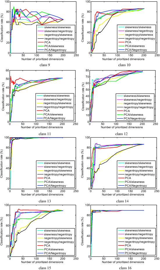
As shown in Figure 20.2, it is very clear that different classes required different numbers of spectral dimensions to achieve their best performance in classification. For example, the easiest cases are class 5 and class 13, where a relatively small number of prioritized dimensions (less than 10) could achieve very high classification rates. To the contrary, the most difficult cases are class 7 and class 9 because both classes only have very few data sample vectors, 26 sample vectors in class 7 and 20 sample vectors in class 9. As a result, the sample size of these two classes is too small to constitute reliable statistics to be used by MLC. This is, in particular, evident when the number of used prioritized dimensions was increased and the performance was actually degraded. Other than these extreme cases, two types of performance are of interest. One is that the classification rates never improved and saturated after a certain number of prioritized dimensions were used, such as classes 2, 5, 6, 8, 13, 14, and 16. Another is that the classification kept improving as the number of used prioritized dimensions was increased, such as classes 3, 11, and 12. There are also many other observations worth discussing based on the results in Figure 20.2 that also allows users to see how PSDE or PSDR performs if prioritized dimensions are progressively added in a forward manner or removed in a backward manner, respectively. These advantages cannot be offered by the traditional DR.
20.6.3 Linear Spectral Mixture Analysis
The land cover/use classification considered in Section 20.6.2 was performed by MLC, which is a hard decision-made classifier, and the Purdue data are, in particular, suitable for its application. However, due to the fact that data sample vectors are heavily mixed, this scene is not applicable to linear spectral unmixing that requires soft decisions in the sense that data sample vectors must be unmixed into a set of abundance fraction maps instead of classification maps produced by MLC. In this case, the 15-panel HYDICE image scene in Figure 1.15(a) was used for experiments where the five panel spectral signatures pi for ![]() plotted in Figure 1.16 were used for spectral unmixing. In order to perform PSDE/PSDR on this image scene, we first estimated the range of feasible values of dimensionality needed to be retained after DR, q. In doing so, VD was used to estimate the number of spectrally distinct signatures that was nVD = 9 with false-alarm probability PF greater than or equal to 10−4. So, if we interpret that a spectrally distinct signature can only be specified by one spectral dimension, this implies that it requires at least nine dimensions to accommodate nine spectrally distinct signatures. In other words, the lower bound to the value of q must be 9. According to the ground truth and visual inspection, there are at least nine signatures present in the scene, as shown in Figure 20.3(a). The fully constrained least-squares (FCLS) method was used to perform spectral unmixing where the signature matrix comprising of the five panel signatures in Figure 1.16 we were obtained from 19 R panel pixels in Figure 20.3(b) and the other four background signatures were obtained by prior knowledge from the areas marked in Figure 20.3(a) as interferer, tree, grass, road. These signatures represented exactly nine signatures estimated by VD. An upper bound to the value of q is then further set by a value twice of VD, that is, 2nVD = 18. Therefore, in the following experiments for PSDE/PSDR, we use q = 9 as a base to back track to q = 5 that represents five panel signatures and to expand forward by extending q to the upper bound, 18.
plotted in Figure 1.16 were used for spectral unmixing. In order to perform PSDE/PSDR on this image scene, we first estimated the range of feasible values of dimensionality needed to be retained after DR, q. In doing so, VD was used to estimate the number of spectrally distinct signatures that was nVD = 9 with false-alarm probability PF greater than or equal to 10−4. So, if we interpret that a spectrally distinct signature can only be specified by one spectral dimension, this implies that it requires at least nine dimensions to accommodate nine spectrally distinct signatures. In other words, the lower bound to the value of q must be 9. According to the ground truth and visual inspection, there are at least nine signatures present in the scene, as shown in Figure 20.3(a). The fully constrained least-squares (FCLS) method was used to perform spectral unmixing where the signature matrix comprising of the five panel signatures in Figure 1.16 we were obtained from 19 R panel pixels in Figure 20.3(b) and the other four background signatures were obtained by prior knowledge from the areas marked in Figure 20.3(a) as interferer, tree, grass, road. These signatures represented exactly nine signatures estimated by VD. An upper bound to the value of q is then further set by a value twice of VD, that is, 2nVD = 18. Therefore, in the following experiments for PSDE/PSDR, we use q = 9 as a base to back track to q = 5 that represents five panel signatures and to expand forward by extending q to the upper bound, 18.
Figure 20.3 (a) A HYDICE panel scene with nine signatures identified by prior knowledge via the ground truth given in (b) which contains 15 panels with ground-truth map of spatial locations of the 15 panels.

To simplify our experiments, only one DR technique was used for experiments that were ATGP- FastICA implemented as ID-ICA-DR, where ATGP and FastICA were used as the initialization driven algorithm and DRT, respectively. ATGP-FastICA was then performed by PSDE with q = 5 growing to q = 18 and by PSDR with q = 18 reduced to q = 5. Figure 20.4 shows the first 18 independent components (ICs) produced by ATGP-FastICA. As we can see from Figure 20.4, the interferers and the panels in the five rows were already separated by FastICA in its first few prioritized ICs.
Figure 20.4 First 18 ICs produced by ATGP-FastICA algorithm.

Now, using the prioritized 18 ICs in Figure 20.4, we further used PSDE to expand image cubes with dimensionality from 5 to 18 to be used as data cubes for FCLS to perform spectral unmixing. Figure 20.5(a)–(n) shows the unmixed results produced by the FCLS operating on the image cubes formed by ICs from 5 to 18.
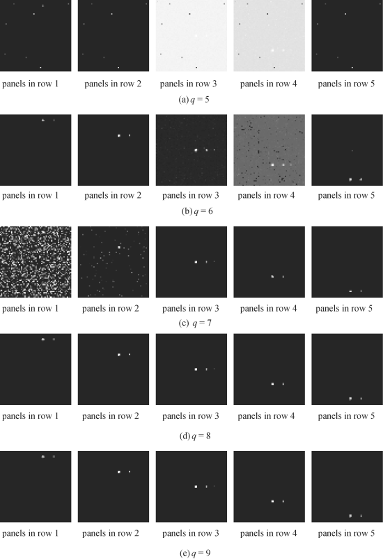

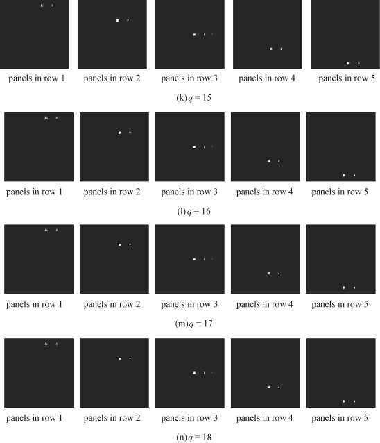
For example, Figure 20.5(a) and (n) was the FCLS-unmixed results of the 15 panels in five rows using the image cube formed by the first five ICs and the entire 18 ICs in Figure 20.4, respectively. The results in Figure 20.5(a)–(n) also revealed that q = 8 was the least number of spectral dimensions to make FCLS work effectively. When q was less than 8, the FCLS-unmixed results were not good. To the contrary, as q was increased from 8 to 18 FCLS consistently performed well in terms of unmixing the 19 panel pixels and there was no visible difference among all the unmixed results. This suggested that q = 8 was the minimal number of spectral dimensions that must be retained after DR and it was very close to the value estimated by VD, nVD = 9. To further confirm this finding, Table 20.1 tabulates the FCLS-unmixed results for q = 8 and 9, where the results obtained for q = 9 are included in parentheses. As shown in Table 20.1, the unmixed results obtained for q = 8 and 9 by FCLS were very close and nearly identical. This implies that there was no additional gain by including more spectral dimensions.
Table 20.1 FCLS quantification for ATGP-FastICA cube with q = 8 (q = 9)

Figure 20.6 illustrates the abundance fractions of 19 R pixels unmixed by FCLS via PSDE/PSDR using a pair of PIs, indicated by PI/PI where the first PI was used to generate projection vectors using ATGP as an ID-PIPP and the second PI was used for PIC prioritization.


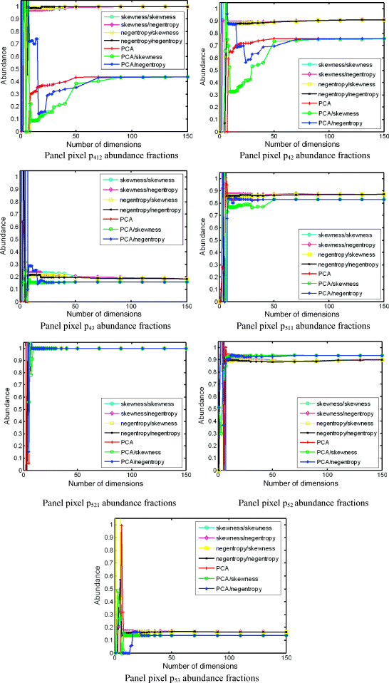
In order to conduct a quantitative study for unmixed results in Figure 20.6, the 3D-ROC analysis developed in Chapter 3 was used for the study. Figure 20.7 only plots the area, Az, calculated under 2D-ROC curves of PD versus PF produced by 3D ROC curves. This results confirmed that the cut-off value for the minimal number of prioritized spectral dimensions, q, to be used for spectral unmixing predicted by nVD = 9 was very accurate if not exact.
Figure 20.7 Plots of areas under 2D ROC curves for averaged classification rate of 19 R panel pixels in Figure 20.6 versus number of prioritized dimensions.
