17.4 Synthetic Image Experiments
Two of six synthetic image-based scenarios in Chapter 4, TI2 in Section 4.3.2.2 and TE2 in Section 4.3.3.2, are particularly selected for experiments and re-described as follows.
Target Implantation 2
The target implantation 2 (TI2) inserts a number of panel pixels into the image by replacing their corresponding BKG pixels. So, the resulting synthetic image has clean panel pixels with perfect knowledge implanted in a noisy BKG corrupted an additive Gaussian noise with a certain level of SNR. TI2 is primarily designed to simulate scenarios with pure pixels implanted as pure signatures to represent true endmembers to evaluate the quantitative performance of SLSMA.
Target Embededness 2
As opposed to TI, the second type of target insertion is target embededness 2 (TE2) that is the same as the TI2 described above except the way the panel pixels are inserted. The BKG pixels were not removed to accommodate the inserted panel pixels as they are done in TI2, but were rather superimposed over the inserted panel pixels. So, in this case, the resulting synthetic image has clean panel pixels embedded in a noisy BKG. The TE2 is particularly designed to simulate scenarios where there are no pure pixels present in the data. As a result, no real true endmembers can be used for LSMA. So, TE2 is more realistic than TI2. Instead, the VSs must be found from TE2. Nevertheless, the complete knowledge of inserted panels and BKG signature is still available for quantitative study and analysis. TE2 is specifically designed to demonstrate the ability of ULSMA in finding VSs.
The synthetic images to be used to simulate TI2 and TE2 for experiments has a size of ![]() pixel vectors with 25 panels of various sizes that are arranged in a
pixel vectors with 25 panels of various sizes that are arranged in a ![]() matrix and located at the center of the scene shown in Figure 17.1 where there are a total of 130 panel pixels present in the scene, 80 pure panel pixels in the first column and 20 pure panel pixels in the second column simulated by the five mineral signatures, A, B, C, K, and M in Figure 1.12(c), 20 mixed panel pixels in the third column simulated by 50% of one of five mineral signatures plus 50% of the other four signatures, five 50%-abundaunce subpanel pixels in the fourth column simulated by 50% of one of five mineral signatures plus BKG signature, and five 25%-abundaunce subpanel pixels in the fifth column simulated by 25% one of five mineral signatures plus 75% of the BKG signature.
matrix and located at the center of the scene shown in Figure 17.1 where there are a total of 130 panel pixels present in the scene, 80 pure panel pixels in the first column and 20 pure panel pixels in the second column simulated by the five mineral signatures, A, B, C, K, and M in Figure 1.12(c), 20 mixed panel pixels in the third column simulated by 50% of one of five mineral signatures plus 50% of the other four signatures, five 50%-abundaunce subpanel pixels in the fourth column simulated by 50% of one of five mineral signatures plus BKG signature, and five 25%-abundaunce subpanel pixels in the fifth column simulated by 25% one of five mineral signatures plus 75% of the BKG signature.
Figure 17.1 A set of 25 panels simulated by A, B, C, K, and M in Figure 1.12(c).
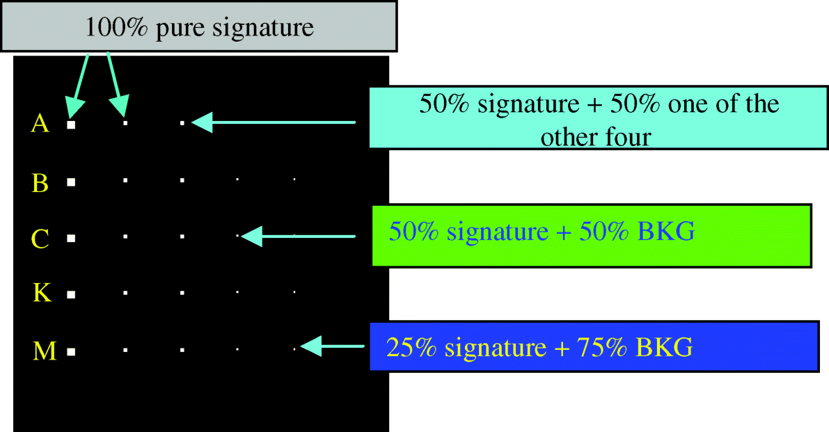
The image BKG in Figure 17.1 is simulated by the sample mean signature in Figure 1.12(a) corrupted by an additive Gaussian noise to achieve a certain signal-to-noise ratio (SNR) that was defined as 50% signature (i.e., reflectance/radiance) divided by the standard deviation of the noise in Harsanyi and Chang (1994).
17.4.1 LS-ULSMA
First of all, assume that no prior knowledge about the scenarios of TI2 and TE2 was provided. In both scenarios the VD-estimated value, nVD was 6 as long as the false alarm probability ![]() . Therefore, nVD = 6 was used for the value of p throughout the experiments. Figures 17.2(a)–(d) and 17.3(a)–(d) show the VSs found by the three LS-based methods, referred to as ATGP-UVSFA, UNCLS-UVSFA, and UFCLS-UVSFA with nVD = 6 for the TI2 and TE2 scenarios, respectively, where (a) the second-order BKG VSs were obtained by applying an unsupervised LS-based algorithm to the original data; (b) high-order target VSs were obtained by applying the same algorithm to the sphered data; (c) the remaining BKG VSs in (a) were obtained after removing those BKG VSs that were also identified as target VSs in (b); (d) total desired VSs obtained by merging the VSs in (b) and (c).
. Therefore, nVD = 6 was used for the value of p throughout the experiments. Figures 17.2(a)–(d) and 17.3(a)–(d) show the VSs found by the three LS-based methods, referred to as ATGP-UVSFA, UNCLS-UVSFA, and UFCLS-UVSFA with nVD = 6 for the TI2 and TE2 scenarios, respectively, where (a) the second-order BKG VSs were obtained by applying an unsupervised LS-based algorithm to the original data; (b) high-order target VSs were obtained by applying the same algorithm to the sphered data; (c) the remaining BKG VSs in (a) were obtained after removing those BKG VSs that were also identified as target VSs in (b); (d) total desired VSs obtained by merging the VSs in (b) and (c).
Figure 17.2 Target VSs extracted by three unsupervised algorithms ATGP-UVSFA, UNCLS-UVSFA, and UFCLS-UVSFA for scenario TI2.
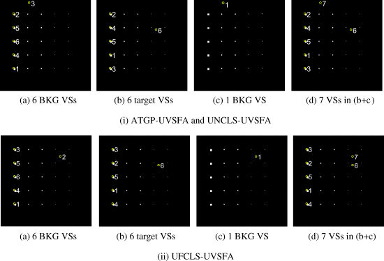
Figure 17.3 Target VSs extracted by three unsupervised algorithms ATGP-UVSFA, UNCLS-UVSFA, and UFCLS-UVSFA for scenario TE2.
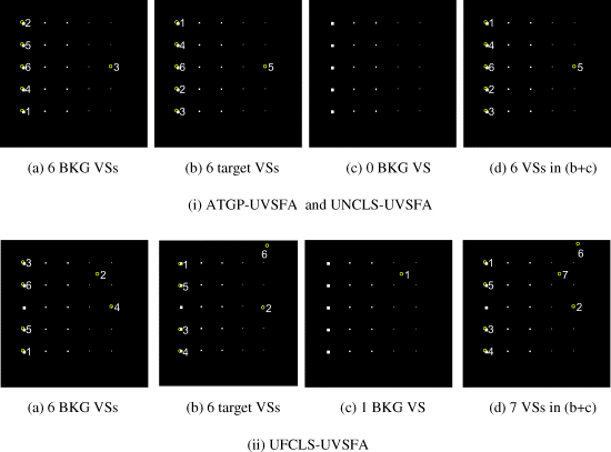
According to the results obtained for the TI2 and TE2 scenarios in Figures 17.2 and 17.3, the VSs found by an LS-based UVSFA can be categorized into ![]() as BKG VSs and
as BKG VSs and ![]() as target VSs. Then the BKG and target VSs were used to form a desired VS matrix
as target VSs. Then the BKG and target VSs were used to form a desired VS matrix ![]() to unmix any given image pixel vector r. Figures 17.4 and 17.5 show the unmixed results of the entire image with each of image pixel vectors unmixed by a set of UVSFA-found nVD VSs,
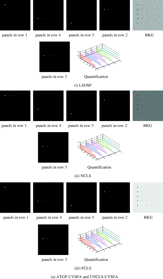
to unmix any given image pixel vector r. Figures 17.4 and 17.5 show the unmixed results of the entire image with each of image pixel vectors unmixed by a set of UVSFA-found nVD VSs,![]() into a set of nVD abundance fraction maps to represent nVD spectral classes for the TI2 and TE2 scenarios, respectively. The LS-based algorithms used by the UVSFA were ATGP, UNCLS and UFCLS for finding VSs. The mixed pixel classification was performed by three linear spectral unmixing methods, least-squares orthogonal subspace projection (LSOSP), non-negativity constrained least squares (NCLS), and fully constrained least squares (FCLS). The results in (i), (ii), and (iii) of Figures 17.4 and 17.5 were obtained by using LSOSP, NCLS, and FCLS to unmix data samples in TI2 and TE2 scenarios via the VS matrix M formed by the target VSs found in Figures 17.2(d) and 17.3(d), respectively, where VSs were identified by the ground truth along with their quantification results for comparison. It should be noted that each figure is arranged in the order of VSs extracted by the UVSFA in Figures 17.2(d) and 17.3(d). Since the whole process was unsupervised the data sample vectors were unmixed by using all VSs including the BKG VSs. Figure 17.5 shows the unmixed results of the scenario TE2 using the target VSs found in Figure 17.3(d). Due to the use of a subpanel pixel
into a set of nVD abundance fraction maps to represent nVD spectral classes for the TI2 and TE2 scenarios, respectively. The LS-based algorithms used by the UVSFA were ATGP, UNCLS and UFCLS for finding VSs. The mixed pixel classification was performed by three linear spectral unmixing methods, least-squares orthogonal subspace projection (LSOSP), non-negativity constrained least squares (NCLS), and fully constrained least squares (FCLS). The results in (i), (ii), and (iii) of Figures 17.4 and 17.5 were obtained by using LSOSP, NCLS, and FCLS to unmix data samples in TI2 and TE2 scenarios via the VS matrix M formed by the target VSs found in Figures 17.2(d) and 17.3(d), respectively, where VSs were identified by the ground truth along with their quantification results for comparison. It should be noted that each figure is arranged in the order of VSs extracted by the UVSFA in Figures 17.2(d) and 17.3(d). Since the whole process was unsupervised the data sample vectors were unmixed by using all VSs including the BKG VSs. Figure 17.5 shows the unmixed results of the scenario TE2 using the target VSs found in Figure 17.3(d). Due to the use of a subpanel pixel ![]() in Figure 17.3(d) as one of the target VSs to unmix the TE2 scenario the resulting abundance fractions for the two subpanel pixels were 100% in Figure 17.5(b). These results were different from Figure 17.5(a) where the target and BKG VSs found by ATGP and UNCLS were used for spectral unmixing and the two subpanel pixels were unmixed into their correct abundance fractions of 50% and 25% of Calcite, respectively. Because LSOSP is unconstrained, the 20 pure panel pixels in row 3 were overestimated in Figure 17.5(b)–(i) by using the subpanel pixel
in Figure 17.3(d) as one of the target VSs to unmix the TE2 scenario the resulting abundance fractions for the two subpanel pixels were 100% in Figure 17.5(b). These results were different from Figure 17.5(a) where the target and BKG VSs found by ATGP and UNCLS were used for spectral unmixing and the two subpanel pixels were unmixed into their correct abundance fractions of 50% and 25% of Calcite, respectively. Because LSOSP is unconstrained, the 20 pure panel pixels in row 3 were overestimated in Figure 17.5(b)–(i) by using the subpanel pixel ![]() as a VS for spectral unmixing.
as a VS for spectral unmixing.
Figure 17.4 Results of using LSOSP, NCLS, and FCLS to unmix TI2 via the target/VSs found in Figure 4(d).


Figure 17.5 Results of using LSOSP, NCLS, and FCLS to unmix TE2 via the target/VSs found in Figure 17.1(d).

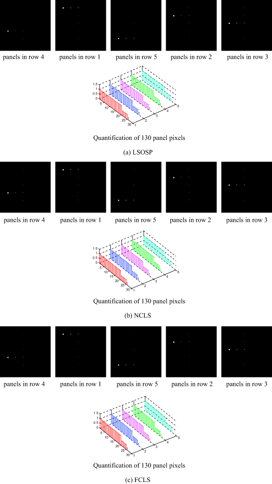
In order to further investigate the above finding, experiments were conducted by using the prior knowledge of the five mineral signatures in Figure 1.12(c) plus the sample mean signature of Figure 1.12(a) to form the signature matrix M for SLSMA to perform spectral unmixing of TI2 and TE2 scenarios using the same three LSMA methods. Figures 17.6(a)–(c) and 17.7(a)–(c) show their unmixed results for all the 130 panel pixels along with their detected abundance fractions for the TI2 and TE2 scenarios, respectively.
Figure 17.6 Results using LSOSP, NCLS, and FCLS to unmix TI2 with assuming prior signature knowledge.
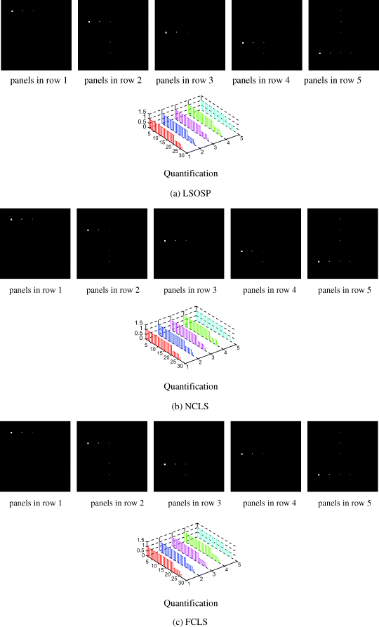
Figure 17.7 Results using LSOSP, NCLS, and FCLS to unmix TE2 with assuming prior signature knowledge.

Comparing the results in Figures 17.6 and 17.7 obtained by SLSMA with Figures 17.4 and 17.5 obtained by USLMA, both SLSMA and ULSMA produced comparable results in terms of quantifying 130 panel pixels for both TI2 and TE2 scenarios except one case of using FCLS to perform SLSMA to unmix TE2 scenario where the resulting abundance fractions for every single panel pixel in row 5 were estimated to be 100% as opposed to zero for every pixel in rows 1–4 as shown in Figure 17.7(c). The reasons for this can be explained as follows. First of all, the target panel pixels in TE2 scenario were superimposed over the BKG pixels so that the abundance fractions of panel pixels and BKG pixels were not summed up to one. However, even though the sum-to-one constraint assumption was violated in TE scenario, FCLS still tried to impose the constraint by giving all abundance fractions to the most distinct spectral signature, Muscovite, that was used to simulate panel pixels in row 5. For this particular case, the ULSMA was superior to the SLSMA because USLMA obtains target knowledge directly from the data where the target panel pixels were not pure anymore and they were actually mixed with the BKG signatures. This knowledge may be more realistic and accurate than the prior knowledge used by the SLSMA where the target panel pixels were assumed to be pure but certainly not true in TE scenario. However, for TI2 scenario the target panel pixels were implanted into the BKG with the corresponding BKG pixels removed to accommodate the inserted target panel pixels in which case the abundance sum-to-one constraint was still valid. As a result, FCLS performed well regardless of whether LSMA was performed in a supervised or an unsupervised manner. Since LSOSP and NCLS did not impose the sum-to-one constraint they also performed well for both TI2 and TE2 scenarios. These experiments also provided strong evidence of importance of using synthetic images to substantiate certain scenarios that were nearly impossible to use real image data to conduct experiments. In addition, with no complete ground truth available real images cannot be used for quantitative data analyses.
17.4.2 CA-ULSMA
As an interesting alternative, this section conducted the same experiments performed by LS-based approaches for comparison. Figure 17.8(a) and (b) shows the six target VSs extracted by maximal IC projections and minimal IC projections respectively for TI scenario. Figure 17.8(c) shows the six BKG VSs extracted by maximum PC projections, while Figure 17.8(d) shows a total of 11 VSs obtained by merging the VSs generated in Figure 17.8(a)–(c).
Figure 17.8 Targets found for scenario TI2: (a) six IC Max VSs; (b) six IC Min VSs; (c) six PC Max VSs; (d) 11 VSs to be used for unmixing.

The 11 VSs generated in Figure 17.8(d) were then used to form a VS matrix to perform linear spectral unmixing. Figure 17.9(a)–(c) is results of three LSMA methods, LSOSP, NCLS, and FCLS where only five target VSs in ![]() corresponding to the five mineral signatures were unmixed. Since the 10 subpanel pixels in fourth and fifth columns are not visible by inspection due to their size smaller than the spatial resolution, the quantification results of the 130 panel pixels are plotted for quantitative analysis where numerals 1–5 represent the number of rows and numerals 1–26 represent panel pixels in a particular row. For example, numbers 1–16, 17–20, 21–24, 25, and 26 represent 16 pixels in the first column, four pixels in the second column, four in the third column, one pixel in the fourth column, and one pixel in the fifth column, respectively. As shown in Figure 17.9 all the three methods performed very well including quantifying the abundances of 130 panel pixels.
corresponding to the five mineral signatures were unmixed. Since the 10 subpanel pixels in fourth and fifth columns are not visible by inspection due to their size smaller than the spatial resolution, the quantification results of the 130 panel pixels are plotted for quantitative analysis where numerals 1–5 represent the number of rows and numerals 1–26 represent panel pixels in a particular row. For example, numbers 1–16, 17–20, 21–24, 25, and 26 represent 16 pixels in the first column, four pixels in the second column, four in the third column, one pixel in the fourth column, and one pixel in the fifth column, respectively. As shown in Figure 17.9 all the three methods performed very well including quantifying the abundances of 130 panel pixels.
Figure 17.9 Results of using LSOSP, NCLS, and FCLS to unmix scenario TI2 via the target pixels found in Figure 17.8(d).
Similar experiments conducted for scenario TI2 were also performed for scenarios TE. Figure 17.10(a)–(c) shows VSs extracted by maximum IC projections, 6 minimal IC projections and 6 maximal PC projections, respectively. Figure 17.10(d) shows 10 VSs obtained by merging the VSs in Figure 17.10(a)–(c).
Figure 17.10 Targets found for scenario TE2: (a) six IC Max VSs; (b) six IC Min VSs; (c) six PC Max VSs; (d) 10 VSs to be used for unmixing.

The 10 VSs generated in Figure 17.10(d) were then used to form a VS matrix to perform spectral unmixing. Figure 17.11(a)–(c) shows results of LSOSP, NCLS, and FCLS along with plotted quantification results of the 130 panel pixels where only 5 target VSs in ![]() corresponding to the five mineral signatures were unmixed.
corresponding to the five mineral signatures were unmixed.
Figure 17.11 Results of using LSOSP, NCLS, and FCLS to unmix scenario TE2 via the target VSs found in Figure 17.10(d).
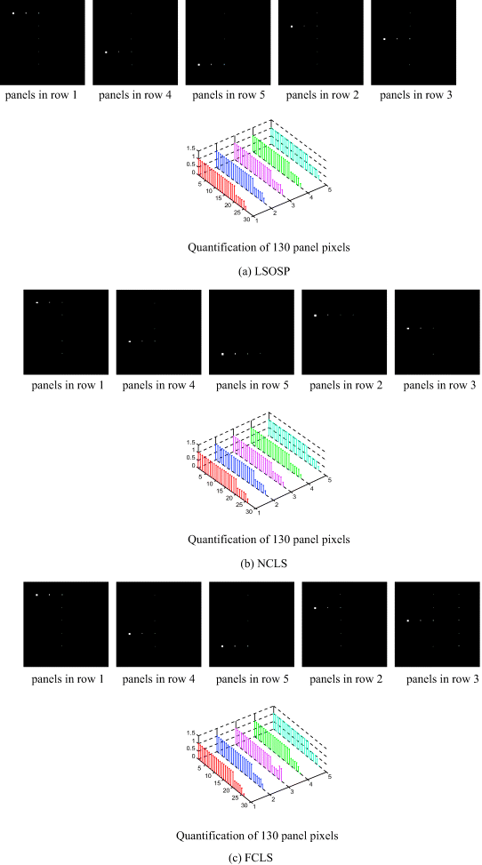
Comparing Figure 17.11 with 17.9 the unmixed results obtained for both scenarios TI2 and TE2 were very close except the two subpanel pixels in row 3 whose FCLS-estimated abundance fractions were 75% way beyond their true abundances. This may due to the fact that TE2 has panel pixels superimposed over the BKG pixels that violated the abundance sum-to-one constraint. This phenomenon will be more evidential in the following SLSMA experiments conducted for the scenario TE2 (Figure 17.13). Other than that the proposed CA-ULSMA performed really well for both scenarios.
In order to conduct a comparative analysis between CA-ULSMA and the SLSMA, we compare the CA-ULSMA results in Figures 17.9 and 17.11 to the results obtained by SLSMA in Figures 17.6 and 17.7. Like LS-ULSMA CA-LSMA also performed as well as LS-LSMA did and also comparably to SLSMA in terms of quantification for both scenarios TI2 and TE2 except the case of TE2 scenario that has been explained in the TI2 experiments where the FCLS-unmixed abundance fractions were unmixed to be 100% for every single panel pixel in row 5 while zero for every pixel in rows of 1–4 as shown in Figure 17.7(c).
As a concluding remark, it is important to realize the importance of the synthetic image-based experiments. With provided complete knowledge of abundance fractions simulated for each of 130 panel pixels we were able to conduct study and analysis on the quantitative performance of LSMA in spectral unmixing which real image experiments generally cannot provide. As shown in experiments, ULSMA using the VSs found by LS-based and CA-based unsupervised VS finding algorithms to perform spectral unmixing could be as at least effectively as SLSMA using real true endmembers. On some occasions such as the case where no real true endmembers are present ULSMA actually outperformed SLSMA due to the fact that the VSs used for ULSMA were real data sample vectors that were more realistic and reliable than the endmembers assumed by prior knowledge or visual inspection. Two additional comments are also worthwhile.
