
Note 8. Reconstructing Physical Signals
The Basic Idea
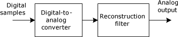
An analog signal is typically reconstructed from a discrete-time signal using a digital-to-analog converter (DAC) followed by a reconstruction filter.
The spectrum of the DAC output signal is distorted by a sinc envelope, with the nulls of the sinc envelope falling in the center of each image other than the baseband.
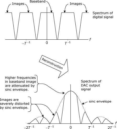
The reconstruction filter must remove the images and correct for the sinc distortion in the baseband. The close spacing between the baseband and the adjacent images can make the design of this filter relatively difficult.
The mathematical signal reconstruction techniques presented in Note 5 do have practical uses, but these techniques are not really suited for converting a sequence of digital signal values back into a continuously time-varying voltage that can be used to drive a speaker or a pair of headphones. Reconstruction of a physical analog signal is usually accomplished using a digital-to-analog converter (DAC). The input to the DAC is a sequence of digital words, and the output is a time-varying voltage that is proportional to the sequence of values represented by the input words. Each output voltage is held constant until the input value changes.
The output of the DAC can be viewed as a special case of the instantaneously sampled signal described in Note 7. In Note 7, each voltage pulse is depicted as being significantly narrower than the sampling interval. The DAC output is a special case in that the DAC typically holds each output value for an entire sampling interval, thereby generating a “stair-step” signal, such as the one shown in Figure 8.2, in which the sample width equals the sampling interval.
Figure 8.1. Block diagram of the signal reconstruction process
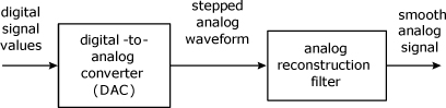
Figure 8.2. Output of DAC modeled as the limiting case of instantaneous sampling

The spectrum of the DAC output contains images and is multiplied by a (sin x) /x envelope, as discussed in Note 7. However, the illustrations in Note 7 depict the case in which the sampling interval, T, is several times larger than the sample width, τ. When the sample width is equal or nearly equal to the sampling interval, the distortion effects caused by the (sin x) /x envelope are much more severe.
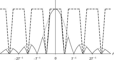
Assume that the ideally sampled signal inside the processing computer has a simple trapezoidal baseband spectrum, as depicted in Figure 8.3. The corresponding DAC output has a spectrum, as shown in Figure 8.4, with the main lobe of the (sin x) /x envelope having a null-to-null width of just twice the sampling rate. All of the images are severely distorted by the side lobes. Because it occupies such a large portion of the main lobe, the baseband component of the spectrum also experiences distortion from the (sin x) /x envelope.
Figure 8.3. Idealized trapezoidal spectrum for a sampled signal, showing (a) the baseband spectrum of the original signal, and (b) spectral images created by the sampling process

Figure 8.4. Spectrum at output of DAC (solid trace). Shown for comparison are the undistorted images of the trapezoidal spectrum (dashed trace) and sinc envelope (dotted trace).
The reconstruction filter that follows the DAC needs to have both a stopband response that severely attenuates the spectral images and a passband response that is designed to correct the (sin x) /x distortion present on the baseband spectrum. When the sample rate equals exactly twice the highest frequency component in the signal’s original spectrum, the signal is said to be critically sampled. When the signal is critically sampled, as in the case depicted in Figure 8.4, the images are close together, thus making it almost impossible to design a filter that can both remove the images and compensate for (sin x) /x distortion. Most filter designs that can remove the images under these conditions are likely to introduce phase distortion into the baseband signal.
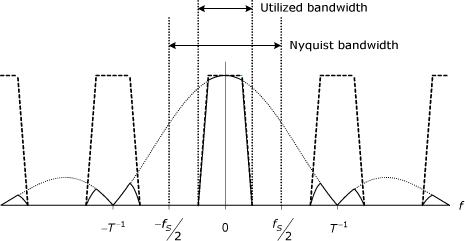
Design and implementation of the reconstruction filter can be made easier by modifying the DAC output signal in a way that separates the spectral images, as shown in Figure 8.5. In many practical systems, the sample rate is already significantly higher than twice the signal bandwidth, which causes the images to be spread farther apart and simplifies the filter design task. In other applications, such as audio CD players, it is necessary to take explicit steps to make the reconstruction problem easier to manage by increasing the Nyquist bandwidth (which is equal to one-half the sample rate) without increasing the utilized bandwidth, as shown in Figure 8.5.
Figure 8.5. Spectrum at output of DAC with 2× oversampling
Audio CD players use a sample rate of 44.1 kHz to support a utilized bandwidth of about 20 kHz, so there would be a gap of about 4 kHz between images in the DAC output. Design of an acceptable reconstruction filter is not impossible, and there were many early CD players built that used direct reconstruction of the 44.1 kHz sample stream. However, CD players are consumer products, and there is constant pressure to make them smaller, lighter, cheaper, and better-sounding. Increasing the CD sample rate would make it easier to build cheaper reconstruction filters with good performance, but an increased sample rate for the recorded signal would require more samples for each second of audio, thus resulting in reduced playing time for a disc having a given total bit capacity.
Most newer CD players advertise 4×, 8×, or even 16× oversampling, but the increased sample rate is not used for the recorded signal. Instead, the digital signal is interpolated to create new sample values in between the sample values that are actually read from the disc. This type of oversampling does not increase the utilized bandwidth; that is, it does not increase the bandwidth of the recorded signal or the reconstructed signal. What it does do is increase the Nyquist bandwidth, which moves the spectral images farther apart so that it becomes relatively easy to design a reconstruction filter that will reject all of the non-baseband images while simultaneously compensating for the (sin x) /x distortion in the baseband spectral component. As shown in Figure 8.5, this oversampling will also have the effect of widening the main lobe of the sinc function so that the utilized bandwidth coincides with a more central, flatter portion of the main lobe, thus lessening the severity of the distortion that the reconstruction filter must correct.
If oversampling is carried throughout the digital processing and if the utilized bandwidth has not already been limited by this processing, then it may be prudent to perform digital filtering to limit the utilized bandwidth just prior to sending the signal to the DAC. Because of the increased Nyquist bandwidth (due to the higher sampling rate), earlier processing may have inadvertantly introduced components outside of the intended signal bandwidth and thereby increased the utilized bandwidth, reducing the effectiveness of the oversampling strategy. On the other hand, if the oversampling is introduced by an interpolation process just prior to sending the signal to the DAC, there is no opportunity to inadvertently increase the utilized bandwidth, and additional filtering would not be necessary.