
Note 57. Polyphase Interpolators
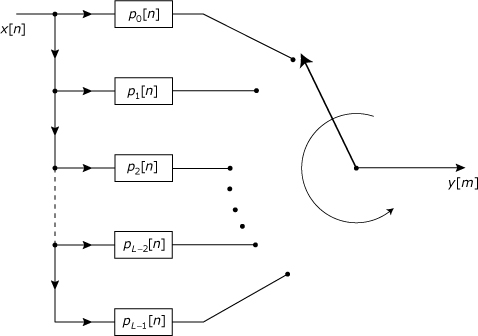
A1-to-L interpolator can be implemented using the polyphase structure shown in Figure 57.1. If h[n] is the response for the interpolation filter when implemented in one of the conventional single-stage structures presented in Note 32, then each individual pρ[n] in Figure 57.1 is a different down sampled version of h[n] obtained as
57.1
![]()
for
n = 0, 1, 2,..., (N/L –1)
ρ = 0, 1, 2,...,(L – 1)
Figure 57.1. A 1-to-L interpolator implemented using a polyphase structure with a commutator
57.1. Why It Works
Consider a conventional interpolator structure consisting of an upsampler followed by a filter. As a result of the upsampler, the input signal to the filter consists of a sequence of single, non-zero samples separated by L–1 interspersed zero-valued samples. Of the N multiplications needed to generate each filter output sample, N(L–1)/L are multiplications by zero. The polyphase approach is motivated by the goal of eliminating these multiplications by zero.
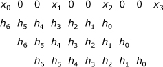
For a signal that has been upsampled by a factor of L, there are L different possible “phasing” alignments between the input samples and the filter coefficients. As depicted in Figure 57.2 for the specific case of L = 3 and N = 7, the possible alignments consist of the following.
• Non-zero inputs align with the filter’s coefficients, h[n,] for which n ≡ 0 (modulo L).
• Non-zero inputs align with the filter’s coefficients, h[n], for which n ≡ 1 (modulo L).
• Non-zero inputs align with the filter’s coefficients, h[n], for which n ≡ L–1 (modulo L).
Figure 57.2. Possible phasing realtionships between the interpolation filter’s input samples and coefficients for the case of M = 3 with N = 7
One way to eliminate the multiplications by zero involves splitting the interpolator into L parallel branches, as shown in Figure 57.3. Each branch corresponds to one of the possible alignments between the input sequence and the filter coefficients. The filter for branch ρ is defined by the sequence of coefficients from h[n] for which n ≡ ρ (modulo L). The zero-valued samples have been eliminated from the filter inputs by moving the upsampling operation from before the filtering to after the filtering. The individual upsamplers in each branch effectively insert the zero-valued results that would have been created had the multiplications by zero not been eliminated. The delays along the right-hand side of the signal flow graph cause the L subsequences to dovetail in the right order needed to create the output y[m]. For any given value of m, only one of the branches contributes a non-zero sample to the summation that creates y[m]; the other L–1 branches contribute zero-valued samples that were injected by their upsamplers.
Figure 57.3. A 1-to-L interpolator implemented as a polyphase structure
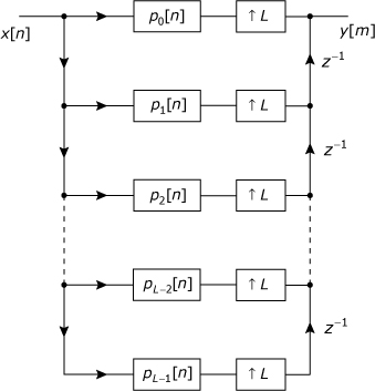
The interpolator structure of Figure 57.3 eliminates multiplication by zero, but a number of additions involving zero-valued terms still remain. These additions can be eliminated by recognizing that because only one branch output is non-zero for each output time, the additions and delays along the right side of the SFG are performing a branch-selection operation that corresponds to the commutator shown in Figure 57.1.
References
1. M. G. Bellanger, G. Bonnerot, and M. Coudreuse, “Digital Filtering by Polyphase Network: Application to Sample-Rate Alteration and Filter Banks,” IEEE Trans. ASSP, vol. 24, no. 2, April 1976, pp. 109–114.
2. R. E. Crochiere and L. R. Rabiner, Multirate Digital Signal Processing, Prentice Hall, 1983.
3. P. P. Vaidyanathan, Multirate Systems and Filter Banks, Prentice Hall, 1993.