Note 43. Bessel Filters
Bessel filters are designed to have maximally flat group-delay characteristics. Consequently, there are no oscillations in the step response, thus making Bessel filters attractive for applications that call for low levels of pulse distortion. The transfer function of an nth-order lowpass Bessel filter is given by
43.1
![]()
where qn(s) is the polynomial of degree n given by
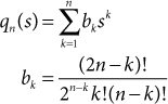
The polynomial qn(s) can be obtained from qn–1(s) and qn–2(s) using the recursion
qn(s) = (2n – 1)qn – 1 + s2qn – 2
Table 43.1 lists qn(s) for n = 2 through n = 8.
Table 43.1. Denominator Polynomials for Transfer Functions of Bessel Filters Normalized to Have Unit Delay at ω = 0
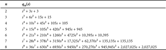
Equation (43.1) does not provide an explicit expression for the poles of a Bessel filter. The pole locations are found by using numerical methods to solve for the roots of qn(s) = 0.
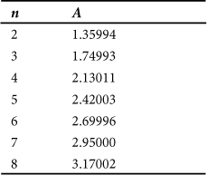
The filters defined by Eq. (43.1) are normalized to have unit delay at ω = 1. The poles, pk, and denominator coefficients, bk, can be renormalized for a 3-dB frequency of ω = 1 using
![]()
where the value of A is obtained from Table 43.2. Odd-order filters have one real pole, and all remaining poles occur in complex-conjugate pairs. The poles for an even-order filter all occur in complex-conjugate pairs. If the denominator factors corresponding to complex-conjugate pairs are multiplied together, the denominator can be expressed as a product of quadratic terms having all real coefficients.
Table 43.2. Factors for Renormalizing Bessel Filter Poles from Unit Delay at ω = 0 to 3-dB Attenuation at ω = 1
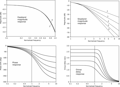
43.1. Frequency Response
Figure 43.1 shows the magnitude, phase, and group-delay responses for lowpass Bessel filters of orders 2 through 6.
Figure 43.1. Frequency response plots for lowpass Bessel filters of orders 2 through 6