
Note 33. Linear-Phase FIR Filters
One of the advantages that FIR filters have over IIR filters is that it is relatively easy to design FIR filters that have constant group delay across all frequencies. Constant group delay is a desireable property for a filter to have because it means that a signal passing through the filter does not experience any delay distortion due to different frequency components being delayed by different amounts. Linear-phase FIR filters are conventionally separated into four types depending upon the four combinations of odd-even filter length and odd-even symmetry in the filter’s impulse response. This note examines these four types of linear-phase FIR filters and their properties.
When a filter has constant group delay (see Note 39, section 39.2), the filter’s phase response is a straight line in the phase-versus-frequency plane—hence, such filters are usually called linear-phase filters. However, in mathematical terms, the phase is a linear function of frequency only if the straight-line phase response passes through the origin of phase-versus-frequency plane and can therefore be expressed as
33.1
![]()
where the constant α is equal to both the filter’s group delay and phase delay. A straight-line phase response that does not pass through the origin can be expressed as
33.2
![]()
Even though Eq. (33.2) defines a straight line, the phase response is not a linear function of frequency because the mathematical definition of linearity is not satisfied, specifically
θ(ω) + θ(ω2)=2β – α(ω1 + ω2)
≠ θ(ω1 + ω2)
Filters that satisfy Eq. (33.2) have constant group delay, but for non-zero β, they do not have constant phase delay. Such filters are properly called constant group delay filters, but historically they have been lumped together with filters that satisfy Eq. (33.1) and are informally referred to as linear-phase filters. True linear-phase filters that have a phase response of the form given by Eq. (33.1) are categorized as either Type 1, if the length of their impulse response is odd, or as Type 2, if the length of their impulse response is even. The properties of Type 1 and Type 2 filters are summarized in List 33.1. Constant-group-delay filters that have a phase response of the form given by Eq. (33.2) are categorized as either Type 3, if the length of their impulse response is odd, or as Type 4, if the length of their impulse response is even. The properties of Type 3 and Type 4 filters are summarized in List 33.2.
Table 33.1 summarizes the frequency response properties for the four different types of linear-phase FIR filters. Each filter’s frequency response, H(ω), is expressed as a product of a complex exponential phase term and a purely real-valued amplitude response, A(ω). The symmetries that the various A(ω) exhibit with respect to ω = 0 and ω = π limit the applications for which each filter type can be used. Because Types 3 and 4 must have A(0) = 0, they are not suitable for use as lowpass or bandstop filters where a nonzero response is needed at ω = 0. Similarly, because they must have A(π) = 0, Types 2 and 3 are not suitable for use as highpass or bandstop filters.
Table 33.1. Frequency Responses for Linear-Phase and Constant-Group-Delay FIR Filters
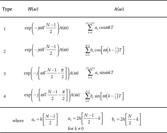
The period of 4π that Table 33.1 gives for the normalized-frequency amplitude response of filter types 2 and 4 is often the source of some consternation. The very definition of “normalized frequency” was set up so that the baseband image of a digital filter’s response spans a normalized frequency interval of ±0.5 cyc/samp or ±π rad/samp. The filter’s response is completely specified by its behavior in a frequency interval of 2π rad/sec, so how can it not be periodic in 2π radians? This issue is discussed at length in Note 34.
List 33.1. Properties of True Linear-Phase FIR Filters
• The phase response, θ(ω), is a linear function of frequency:
33.1
![]()
where the constant α is both the phase delay and the group delay of the filter in units of sample intervals.
• The phase response is a straight line, with a slope of α, passing through the origin of the phase-versus-frequency coordinate plane.
• For an FIR filter having N coefficients, there is a unique value of α for which a linear phase is produced. This value is given by
33.2
![]()
• In order to achieve a linear-phase response, the impulse response of the filter must exhibit even symmetry:
33.3
![]()
• For a Type 1 filter, the number of taps, N, is odd, and the center of symmetry coincides with the sample at n = (N – 1)/2, as shown in Figure 33.1(a).
Figure 33.1. Impulse responses for linear-phase FIR filters: (a) the coefficients for a Type 1 filter exhibit even symmetry about n = (N – 1)/2, and (b) the coefficients for a Type 2 filter exhibit even symmetry about the abscissa, midway between n = (N – 2)/2 and n = N/2.
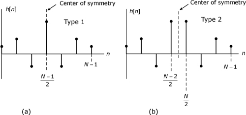
• For a Type 2 filter, the number of taps, N, is even, and the center of symmetry falls midway between the sample at n = (N – 2)/2 and the sample at n = N/2, as shown in Figure 33.1(b).
List 33.2. Properties of Constant-Group-Delay FIR Filters
• The phase response, θ(ω), has constant slope but is not constrained to pass through the origin of the phase-versus-frequency coordinate plane:
33.1
![]()
• For a filter having N coefficients, there are unique values of α and β for which this phase response can be produced, and these values are given by
33.2
![]()
• In order to achieve the phase response of (33.1), the impulse response must be odd symmetric or antisymmetric, that is, h[n] must satisfy
33.3
![]()
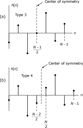
• For a Type 3 filter, the number of taps, N, is odd and the center of antisymmetry coincides with the sample at n = (N – 1)/2, as shown in Figure 33.2(a). When n = (N – 1)/2 with N odd, Eq. (33.3) yields
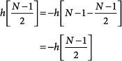
Figure 33.2. Impulse responses for constant-group-delay FIR filters: (a) Type 3 filter has odd symmetry about n = (N – 1)/2; (b) Type 4 has odd symmetry about the abscissa, midway between n = (N – 2)/2 and n = N/2.
Therefore, h[(N – 1)/2] must always equal zero in Type 3 filters.
• For a Type 4 filter, the number of taps, N, is even, and the center of antisymmetry falls midway between the sample at n = (N – 2)/2 and the sample at n = N/2, as shown in Figure 33.2(b).