Note 40. Butterworth Filters
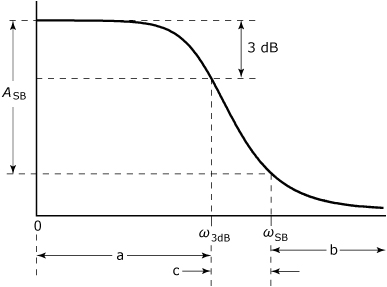
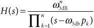
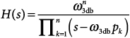
Lowpass Butterworth filters are designed to have a magnitude response that is as flat as possible at low frequencies, and that decreases monotonically with increasing frequency, as shown in Figure 40.1. A lowpass Butterworth filter has a transfer function of the form shown in Math Box 40.1. Examination of this transfer function reveals that a Butterworth lowpass filter is an all-pole design that is completely specified by just two parameters—the number of poles, n, and the 3-dB cutoff frequency, ω3dB. The number of poles is usually set to acheive a desired amount of attenuation, ASB, at and above some specified stopband-edge frequency, ωSB. This frequency and the amount of stopband attenuation are not direct specifications on the filter—they are only indirect specifications that are used to determine the minimum required number of poles using Eq. (MB 40.2).
Figure 40.1. Magnitude response showing critical features and parameters used to specify a Butterworth filter: (a) passband, (b) stopband, (c) transition band
Math Box 40.1. Characteristics of Lowpass Butterworth Filters
Transfer Function
MB 40.1
where
Minimum Order
MB 40.2
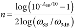
where
ASB = minimum stopband attenuation
ω3dB = frequency at which passband response is 3 dB below peak
ωSB = frequency that defines the start of the stopband
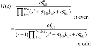
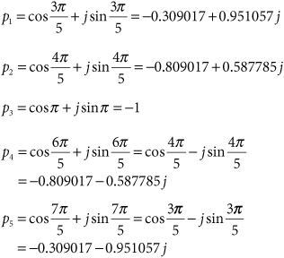
The poles for a Butterworth LPF always lie at equally spaced points on the left half of the unit circle in the s plane, as shown in Figure 40.2. Odd-order filters have one real pole at s = –1, and all remaining poles occur in complex-conjugate pairs. The poles for an even-order filter all occur in complex-conjugate pairs. If the denominator factors corresponding to complex-conjugate pairs in Eq. (MB 40.1) are multiplied together, the transfer function’s denominator can be expressed as a product of quadratic terms having all real coefficients:
40.1
where
bk = –2σk = –Re{Pk}
Figure 40.2. Pole locations for lowpass Butterworth filters: (a) fourth-order and (b) fifth-order
40.1. Frequency Response
Figure 40.3 shows the magnitude, phase, and group delay responses for lowpass Butterworth filters of orders 1 through 6.
Figure 40.3. Frequency response plots for lowpass Butterworth filters of orders 1 through 6

40.2. Prototype Considerations
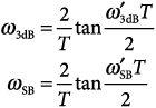
Bilinear transformation (see Note 51) distorts, or “warps,” the frequency axis in mapping an analog filter into the corrresponding IIR digital filter. Typically, critical frequencies used to specify the filter’s performance are “prewarped” to compensate for the warping that occurs in the bilinear transformation. As indicated in Design Procedure 40.1, if a Butterworth filter is to be used as a prototype for the bilinear transformation, it is important to do the prewarping of ω3dB and ωSB before these frequencies are used to determine the necessary filter order.
Example 40.1. Butterworth Prototype
Use Design Procedure 40.1 to design a Butterworth prototype filter that will be used in the bilinear transformation to design an IIR filter that meets the following specifications:
• The 3-dB cutoff frequency is 3 kHz.
• The sampling rate is 30,000 samples per second.
• At least 30 dB of attenuation is at frequencies at or above 6 kHz.
The prewarped cutoff frequency for the prototype is obtained as
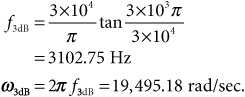
The prewarped stopband frequency is obtained as
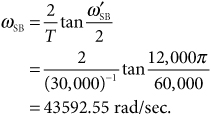
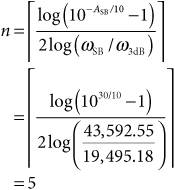
The minimum number of poles is obtained as
Finally, the protoype’s transfer function is given by
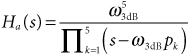
where
Design Procedure 40.1. Designing a Butterworth Prototype
- Based on the requirements of the intended application, determine desired values for the following critical performance parameters to be exhibited by the final IIR design:
 = 3–dB cutoff frequency
 = stopband-edge frequency
ASB = maximum stopband level in dB
- Determine the prewarped frequencies, ω3dB, and ωSB, corresponding to the desired final frequencies, and . If the prototype is being designed for use in the bilinear transformation, the prewarped frequencies are given by
where

- Determine the minimum filter order as

- Generate the transfer function for the analog prototype filter as
where