Note 52. Decimation: The Fundamentals
This note introduces the fundamental concepts involved in decimation, which is the name given to the process of decreasing a discrete-time signal’s sampling rate while leaving all other characteristics of the signal unchanged to the maximum extent possible.
Decimation is based on the notion that some discrete-time signal of interest exists in a form that is significantly over sampled. There may be some noise and interference throughout the entire bandwidth of ± FS/2 that is supported by the sample rate, FS, but the signal of interest has a spectrum that is confined to a bandwidth much smaller than ± FS/2.
Consider a discrete-time signal having the periodic spectrum shown in Figure 52.1(a). The spectral images are centered on integer multiples of the sampling rate, FS, and there may be significant amounts of interference between the passband images as shown. The goal of the decimation process is to decrease the signal’s sample rate by some factor, say, M, in such a way that the new signal’s spectrum is similar to the one depicted in Figure 52.1(c).
Figure 52.1. Spectrum of a discrete-time signal at key points in the decimation process: (a) original spectrum, (b) spectrum after lowpass filtering, and (c) spectrum after downsampling by a factor of 3.
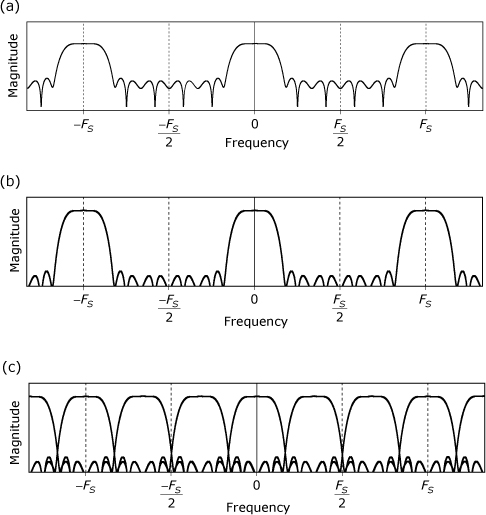
The spectral images in the new spectrum correspond to the portions of interest contained in the images in the original spectrum, but they are centered on integer multiples of the new sampling rate, FS/M. The interference bands from the original spectrum must be attenuated, as shown in Figure 52.1(b), so that they alias in to the new passband images at acceptably low levels. The basic process for decimation is provided in Recipe 52.1.
Recipe 52.1. Signal Decimation
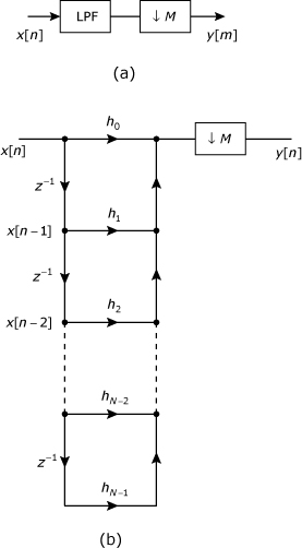
As depicted in the block diagram, the canonical form of decimation consists of just two steps:
![]()
- Pass the signal through a digital lowpass filter that is designed to pass the signal of interest (SOI) while attenuating any noise or interference that may exist outside of the bandwidth occupied by the SOI. This filter is just another application of the familiar anti-aliasing filter. Figure 52.1(a) shows the spectrum of a typical signal, and Figure 52.1(b) shows the spectrum after the signal has been filtered to (1) reduce the inter-image interference levels, and (2) make the transition bands slightly narrower than in the original spectrum.
- Retain every Mth sample from the signal while discarding all others. This step is referred to as either downsampling or sample rate reduction. Figure 52.1(c) shows the signal’s spectrum after downsampling by a factor of 3.
Designing the anti-aliasing filter for a decimator can sometimes be a difficult task, especially when the value of M is large. The filter’s passband edge must be high enough to pass the complete portion of interest from the baseband image, while the stopband edge must be low enough to severely attenuate all noise and interference at frequencies beyond the new (that is, post-downsampling), folding frequencies of FS/(2M).
52.1. Efficient FIR Decimators
The direct form for implementing a decimator is shown in Figure 52.2. Part (a) of the figure shows the usual block diagram representation for a decimator, while part (b) uses a signal flow graph to show the direct-form-1 implementation for the anti-aliasing filter. The filter must perform N multiplications each time a new input sample is clocked in. If the input sample rate is FS, the multiplication burden imposed by the filter is NFS multiplications per second.
Figure 52.2. Direct form decimator structures: (a) block diagram and (b) with signal flow graph showing detail for direct form filter implementation
Any form—FIR or IIR, direct or transposed—of lowpass filter can be used to implement a decimator, but the FIR direct-form-1 lends itself to further simplification by allowing the downsampler to be moved inside of the filter. The downsampler can be replaced by N downsamplers, with one placed at the output of each multiplier, as shown in Figure 52.3(a). Whether the downsampler discards a sample before or after it is multiplied by hn makes no difference in the result, so the order of multiplication and downsampling can be commuted to obtain the structure shown in Figure 52.3(b). To generate each output sample, this structure must perform N multiplications. The output sample rate is FS/M, so the multiplication burden imposed by the filtering is only NFS/M multiplications per second. The concept of moving the downsampling to occur prior to the coefficient multiplication can be extended to the structures that are presented in Note 32 for the special case of symmetric responses for linear-phase FIR filters. Figure 52.4 shows the locations of the downsamplers that must be added to contruct a decimator built upon the FIR structure given in Figure 32.7 of Note 32.
Figure 52.3. Decimator structures: (a) direct-form-1 FIR filter with downsampling moved into each multiplier branch; (b) efficient structure with downsampling and multiplication transposed in each branch
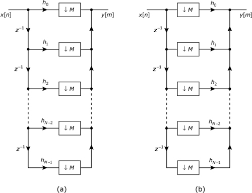
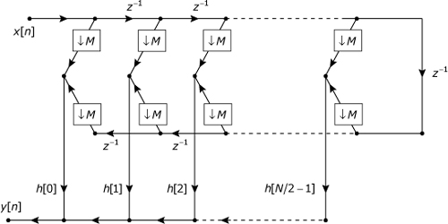
Figure 52.4. Efficient decimator structure that incorporates a Type 2 (even length, even symmetry) linear-phase FIR filter