
Note 51. Designing IIR Filters: Bilinear Transformation
The bilinear transformation is the most commonly used approach for designing IIR filters. As discussed in Note 50, the impulse invariance technique uses a many-to-one frequency mapping that maps multiple intervals from the jω axis in the s-plane repeatedly onto the same points on the unit circle in the z-plane. This mapping can introduce aliasing of the filter response, making the impulse invariance technique unsuitable for use in designing highpass or bandstop filters. The bilinear transformation uses a nonlinear frequency mapping such that the entire jω axis of the s-plane maps one-to-one onto points of the unit circle of the z-plane. The mapping avoids aliasing, but it does “warp” critical frequencies of the analog prototype into different frequencies for the corresponding features in the digital filter’s response.
51.1. Prewarping
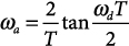
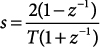
The s-plane to z-plane mapping that results from the bilinear transformation is depicted in Key Concept 51.2. This “warped” frequency relationship becomes increasingly compressed at higher frequencies, resulting in a need to prewarp the critical frequencies in such a way that these frequencies warp into the desired locations in the final IIR design. The usual strategy for mitigating the effect of frequency warping involves prewarping the critical frequencies using the relationship
51.1
![]()
where T is the sampling interval, ωd is the desired frequency in the final IIR design, and ωa is the prewarped frequency to be used in the design of the analog prototype.
The details of the bilinear transformation (with prewarping included) are provided in Recipe 51.1.
Example 51.1 demonstrates a manual application of this procedure. Several MATLAB-based approaches for the bilinear transformation are demonstrated in Example 51.2.
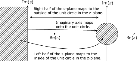
Key Concept 51.1. Bilinear Transformation’s Frequency Mapping Avoids Aliasing
In the frequency conversion used by the bilinear transformation, the analog frequency’s domian of ±∞ maps one-to-one into a digital frequency range of ±π. This mapping avoids aliasing that often occurs in the impulse invariant maping that was presented in Note 50.
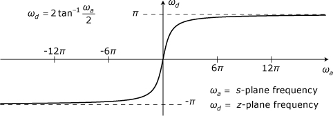
Key Concept 51.2. Bilinear Frequency Mapping Warps Critical Frequencies
The mapping from the s-plane to the z-plane creates the relationship between s-plane frequencies and z-plane frequencies that is depicted below. This “warped” frequency relationship becomes increasingly compressed at higher frequencies, resulting in a need to prewarp the critical frequencies in the analog prototype so that these frequencies warp into the desired locations in the final IIR design.
Recipe 51.1. Bilinear Transformation
- Select the basic family (Butterworth, Chebyshev, and so on) for the analog prototype filter using information from Notes 40 through 43.
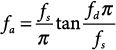
- For each critical frequency, ωd, in the targeted IIR filter, determine the corresponding “prewarped” frequency to use in designing the analog prototype as
R 51.1
or
R 51.2
- Using design formulas from Notes 40 through 43, along with the prewarped frequencies from step 2, obtain the transfer function, Ha(s), for the desired analog prototype filter.
- Transform Ha(s) into the system function, H(z), by making the substitution
R 51.3
where T is the sampling interval for the digital filter.
- Perform the necessary algebraic manipulations to put H(z) into the form of a ratio of polynomials in z–1:
R 51.4
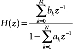
- Use the ak and bk values to implement the IIR filter in one of the structures presented in Note 49.
Example 51.1. Manual Application of the Bilinear Transformation
Use Recipe 51.1 to obtain an IIR filter for a second-order Butterworth analog prototype. The desired 3-dB cutoff frequency is 3 kHz, and the sampling rate is 30,000 samples per second.
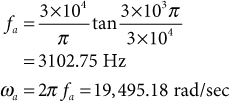
The prewarped cutoff frequency for the prototype is obtained as
The transfer function for a second order Butterworth filter is given by
![]()
Substitution of Eq. (R 51.3) for s yields
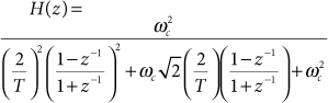
Setting ωc = ωa = 19,495.18 and T = (30,000)–1 then yields
51.2
![]()
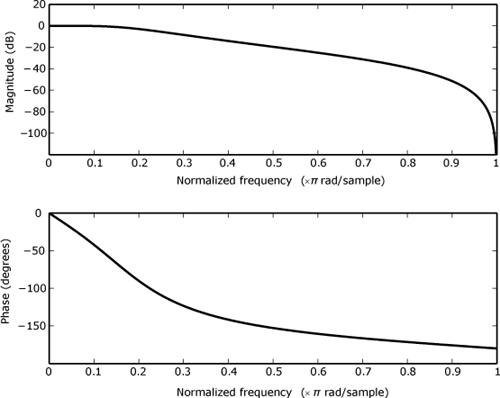
The magnitude and phase response shown in Figure 51.1 can be obtained using the MATLAB function freqz(b,a,1024) with
a=[1 -1.142981 0.412802]
and
b=[0.067455 0.13491 0.067455].
Figure 51.1. Frequency response for IIR filter from Example 51.1
Example 51.2. Bilinear Transformation Using MATLAB
Manual application of the bilinear transformation quickly becomes tedious and error-prone as the filter order is increased. As with many other design techniques for digital filters, some sort of computer-aided design tool is essential for practical applications. In this example we use MATLAB to design an IIR filter based on a Butterworth prototype. The desired 3-dB cutoff frequency is 3 kHz, and the sampling rate is 30,000 samples per second. MATLAB is rich with signal processing tools and there are a number of different ways these tools can be used to obtain our desired filter. The MATLAB function butter can be used to design either analog or digital IIR Butterworth filters. The call
[zd, pd, kd] = butter(n,Wn);
designs an IIR Butterworth lowpass filter of order n with a normalized 3-dB cutoff frequency of Wn. The cutoff frequency is normalized based on half the sampling rate equaling 1 rather than the more common practice of normalizing based on a sampling rate equal to 1. In this example, the normalized cutoff frequency for butter would be Wn=0.2. The first output, zd, is a column vector containing zeros of the filter’s system function. The second output, pd, is a column vector containing poles of the filter’s system function. The third output, kd, is a constant gain factor that has been removed from the filter’s zeros so that the constant term in the system function’s numerator polynomial equals 1. If we use butter to design the second order filter from Example 51.1, the results are
zd =
-1
-1
pd =
0.5714902512699 + 0.2935992009519i
0.5714902512699 - 0.2935992009519i
kd =
0.067455273889072
The numerator and denominator polynomials for H(z) can be obtained using the MATLAB poly function
>>bd=poly(zd)
bd =
1 2 1
>>ad = poly(pd)
ad =
1.00000000000000 -1.14298050253990
0.41280159809619
This result corresponds to
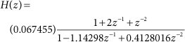
and agrees with Eq. (51.2) to within a small amount of numerical error.
A second MATLAB-based approach explicitly generates the poles and zeros for the transfer function of the analog prototype and then applies the bilinear transformation as a separate step. The call
[z, p, k] = butter(n, Wn,'s'),
designs an analog Butterworth lowpass filter of order n with a 3-dB cutoff ffequency of Wn radians per second. The call
[zd,pd,kd] = bilinear(z,p,k,fs);
uses the bilinear transformation to convert the analog transfer function defined by [z,p,k] into the discrete-time system function defined by [zd,pd,kd] with a sampling rate of fs. Thus the desired IIR filter for this example can be generated using
>> wd = 6000*pi;
>> T = 1/30000;
>> wa = (2/T)*tan(wd*T/2)
>> [z,p,k] = butter(2,wa,'s'),
>> [zd,pd,kd] = bilinear(z,p,k,30000);
>> ad=poly(pd)
ad =
1.000000000000000 -1.142980502539901
0.412801598096189
>> bd=poly(zd)
bd =
1 2 1
>> kd
kd =
0.067455273889072
Once again, the results for ad, bd, and kd agree with Eq. (51.2) to within a small amount of numerical error.
MATLAB provides an alternate form of bilinear that automatically performs prewarping for a single frequency. The calling sequence for this form is
[zd,pd,kd] = bilinear(z,p,k,fs,fd);
where fd is the critical frequency upon which the prewarping is to be based. Using this form of bilinear, the desired IIR filter can be designed using
>> [z,p,k] = butter(2,6000*pi,'s'),
>> [zd,pd,kd] = bilinear(z,p,k,30000,3000);