Creating the Missile Body
The main body of our missile is simply a long cylinder to which we will later add different parts. For most of this drawing we will use the Perspective viewport so we can actually see our final image as we draw.
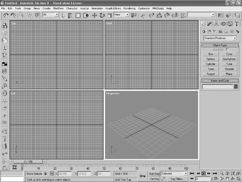
Click anywhere in the Perspective viewport to select this window. A yellow border will appear around the window. Click on the Maximize viewport toggle button (or use the shortcut Alt+W) to maximize this viewport and hide the others, as seen in Figure 10.10.
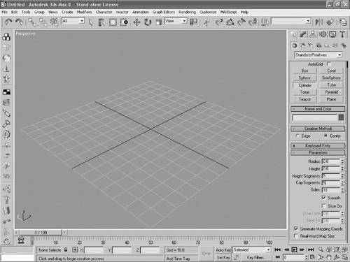
Click Create > Standard Primitives > Cylinder. You can now set certain parameters for your cylinder.
Expand the Parameters panel by clicking on the + beside the word “parameters” if it is not already expanded.
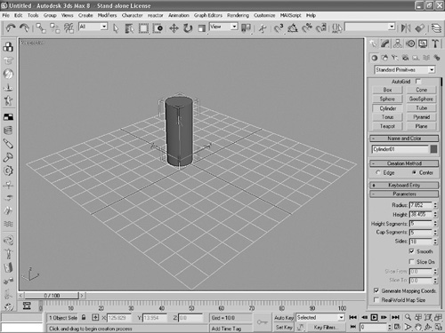
Enter 5 for both the Height Segments and Cap Segments, as shown in Figure 10.11. This is a very important step; if you don’t do this, you’ll have trouble later on.
Figure 10.11. Make sure that you enter a 5 in the Cap Segments portion of the Parameters panel.
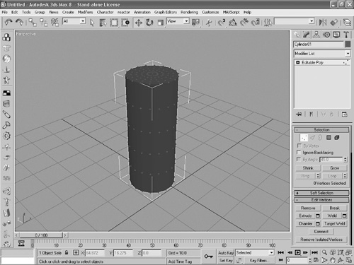
Click and drag a circle across the screen. It doesn’t matter what size it is; we’ll adjust this later. When you release the mouse button, you’ll be able to adjust the height of the cylinder. Drag upwards to extend the cylinder, and then release the mouse button. You should now have a cylinder similar to the one in Figure 10.12.
Now we are going to taper off the peak of the cylinder to make it look like a missile head. We’ll do this by converting the cylinder into an editable poly and stretching out the peak of the cone. Click on the Modify panel if it’s not already selected.
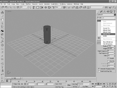
Right-click on the word “cylinder” and select Editable Poly from the menu that appears (see Figure 10.13).
Figure 10.13. In the Modify panel, right-click on the word “cylinder” and select Editable Poly.
Click on the Select and Move button in the toolbar. In the Selection panel, click on the Vertex button (three red dots). You should now see a series of dots appear all around the cylinder, as in Figure 10.14. We’ll manipulate these dots in order to change the shape of the cylinder.
Figure 10.14. When you select the Vertex button, a series of dots will appear around the cylinder.
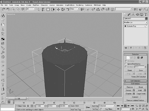
Click Vertex in the very middle of the cylinder. It should turn red, and three arrows should appear around it, as in Figure 10.15. You may have to zoom in to accomplish this. You can zoom in by selecting the Zoom tool (the magnifying glass at the bottom right of the screen) and clicking and dragging upwards. You can then pan to the top of the cylinder by using the Pan tool (the little white hand).
Figure 10.15. Select the center vertex and a series of arrows will appear around it.
Expand the Soft Selection panel if it is not already expanded. In this panel, click the check box labeled Use Soft Selection. In the Falloff box, enter the number 20. The vertexes on top of the cylinder should be orange and yellow.
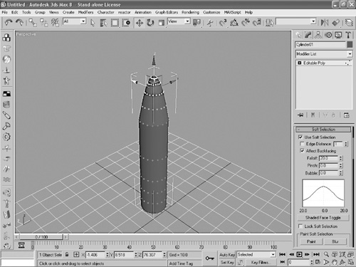
Position your mouse pointer over the blue z arrow and click and drag upwards until the cylinder has a cone peak, as in Figure 10.16.
Figure 10.16. After you’ve created a 20-unit soft selection, click and drag upwards on the blue z arrow to create a peak out of the top of the cylinder.
Click on Editable Poly in the Modifier list. It will turn from yellow to gray, and the vertexes will no longer appear on the cylinder.