
4.2 Gates
The gates in a computer are sometimes referred to as logic gates because each performs just one logical function. That is, each gate accepts one or more input values and produces a single output value. Because we are dealing with binary information, each input and output value is either 0, corresponding to a low-voltage signal, or 1, corresponding to a high-voltage signal. The type of gate and the input values determine the output value.
Let’s examine the processing of the following six types of gates. We then show how they can be combined into circuits to perform arithmetic operations.
NOT
AND
OR
XOR
NAND
NOR
In this book we have colorized the logic diagram symbols for each gate to help you keep track of the various types. When we examine full circuits with many gates, the colors will help you distinguish among them. In the real world, however, logic diagrams are typically black and white, and the gates are distinguished only by their shape.
NOT Gate
A NOT gate accepts one input value and produces one output value. FIGURE 4.1 shows a NOT gate represented in three ways: as a Boolean expression, as its logical diagram symbol, and through a truth table. In each representation, the variable A represents the input signal, which is either 0 or 1. The variable X represents the output signal, whose value (0 or 1) is determined by the value of A.

FIGURE 4.1 Representations of a NOT gate
By definition, if the input value for a NOT gate is 0, the output value is 1; if the input value is 1, the output is 0. A NOT gate is sometimes referred to as an inverter because it inverts the input value.
In Boolean expressions, the NOT operation is represented by the ‘ mark after the value being negated. Sometimes this operation is shown as a horizontal bar over the value being negated. In the Boolean expression in Figure 4.1, X is assigned the value determined by applying the NOT operation to input value A. In such an assignment statement, the variable on the left of the equal sign takes on the value of the expression on the right-hand side. Assignment statements are discussed further in Chapter 6.
The logic diagram symbol for a NOT gate is a triangle with a small circle (called an inversion bubble) on the end. The input and output are shown as lines flowing into and out of the gate. Sometimes these lines are labeled, though not always.
The truth table in Figure 4.1 shows all possible input values for a NOT gate as well as the corresponding output values. Because there is only one input signal to a NOT gate, and that signal can be only a 0 or a 1, there are only two possibilities for the column labeled A in the truth table. The column labeled X shows the output of the gate, which is the inverse of the input. Note that of the three representations, only the truth table actually defines the behavior of the gate for all situations.
These three notations are just different ways of representing the same thing. For example, the result of the Boolean expression
0‘
is always 1, and the result of the Boolean expression
1‘
is always 0. This behavior is consistent with the values shown in the truth table.
AND Gate
FIGURE 4.2 depicts an AND gate. Unlike a NOT gate, which accepts one input signal, an AND gate accepts two input signals. The values of both input signals determine what the output signal will be. If the two input values for an AND gate are both 1, the output is 1; otherwise, the output is 0.
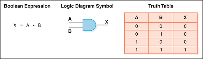
FIGURE 4.2 Representations of an AND gate
The AND operation in Boolean algebra is expressed using a single dot (·). Sometimes an asterisk (*) is used to represent this operator. Often the operator itself is assumed. For example, A · B is often written AB.
Because there are two inputs and two possible values for each input, four possible combinations of 1 and 0 can be provided as input to an AND gate. Therefore, four situations can occur when the AND operator is used in a Boolean expression:
0 · 0 equals 0
0 · 1 equals 0
1 · 0 equals 0
1 · 1 equals 1
Likewise, the truth table showing the behavior of the AND gate has four rows, showing all four possible input combinations. The output column of the truth table is consistent with results of these Boolean expressions.
OR Gate
FIGURE 4.3 shows an OR gate. Like the AND gate, the OR gate has two inputs. If both input values are 0, the output value is 0; otherwise, the output is 1.
FIGURE 4.3 Representations of an OR gate

The Boolean algebra OR operation is expressed using a plus sign (+). The OR gate has two inputs, each of which can be one of two values. Thus, as with an AND gate, there are four input combinations and therefore four rows in the truth table.
XOR Gate
The XOR, or exclusive OR, gate is shown in FIGURE 4.4. An XOR gate produces a 0 if its two inputs are the same, and a 1 otherwise. Note the difference between the XOR gate and the OR gate; they differ in only one input situation. When both input signals are 1, the OR gate produces a 1 and the XOR produces a 0.

FIGURE 4.4 Representations of an XOR gate
Sometimes the regular OR gate is referred to as the inclusive OR, because it produces a 1 if either or both of its inputs is a 1. The XOR produces a 1 only if its inputs are mixed (one 1 and one 0). Think of the XOR gate as saying, “When I say or, I mean one or the other, not both.”
The Boolean algebra symbol % is sometimes used to express the XOR operation. In addition, the XOR operation can be expressed using the other operators; we leave that as an exercise.
Note that the logic diagram symbol for the XOR gate is just like the symbol for an OR gate except that it has an extra curved line connecting its input signals.
NAND and NOR Gates
The NAND gate is shown in FIGURE 4.5 and the NOR gate is shown in FIGURE 4.6. Each accepts two input values. The NAND and NOR gates are essentially the opposites of the AND and OR gates, respectively. That is, the output of a NAND gate is the same as if you took the output of an AND gate and put it through an inverter (a NOT gate).
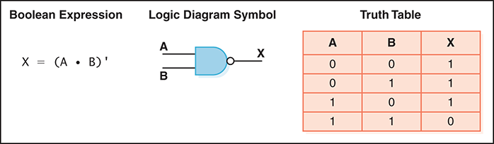
FIGURE 4.5 Representations of a NAND gate
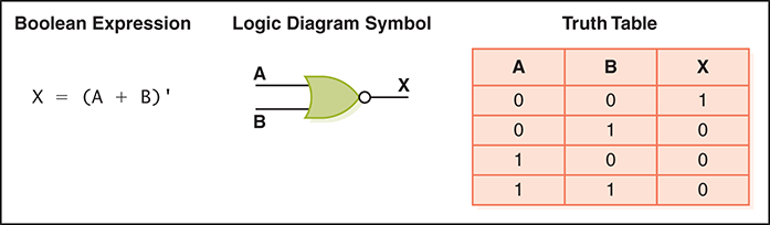
FIGURE 4.6 Representations of a NOR gate
No specific symbols are used to express the NAND and NOR operations in Boolean algebra. Instead, we rely on their definitions to express the concepts. That is, the Boolean algebra expression for NAND is the negation of an AND operation. Likewise, the Boolean algebra expression for NOR is the negation of an OR operation.
The logic diagram symbols for the NAND and NOR gates are the same as those for the AND and OR gates, except that the NAND and NOR symbols use an inversion bubble (to indicate the negation). Compare the output columns for the truth tables for the AND and NAND gates. They are opposites, when you look at them row by row. The same is true for the OR and NOR gates.
Review of Gate Processing
We’ve looked at six specific types of gates. It may seem to be a difficult task to keep them straight and remember how they all work—but that probably depends on how you think about it. We definitely don’t encourage you to try to memorize truth tables. The processing of these gates can be described briefly in general terms. If you think of them in that way, you can produce the appropriate truth table any time you need it.
Let’s review the processing of each gate. Some of these descriptions are stated in terms of which input values cause the gate to produce a 1 as output; in any other case, the gate produces a 0.
A NOT gate inverts its single input value.
An AND gate produces 1 if both input values are 1.
An OR gate produces 1 if one or the other or both input values are 1.
An XOR gate produces 1 if one or the other (but not both) input values are 1.
A NAND gate produces the opposite results of an AND gate.
A NOR gate produces the opposite results of an OR gate.
With these general processing rules in mind, all that’s left is to remember the Boolean operators and the logic diagram symbols. Keep in mind that several logic diagram symbols are variations on other logic diagram symbols. Also, remember that the coloring of the gates in this book is meant to help you to keep track of the various gate types; traditionally, they are simply black-and-white diagrams.
Gates with More Inputs
Gates can be designed to accept three or more input values. A three-input AND gate, for example, produces an output of 1 only if all input values are 1. A three-input OR gate produces an output of 1 if any input value is 1. These definitions are consistent with the two-input versions of these gates. FIGURE 4.7 shows an AND gate with three input signals.
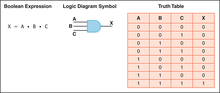
FIGURE 4.7 Representations of a three-input AND gate
There are 23, or 8, possible input combinations for a gate with three inputs. Recall from Chapter 3 that there are 2n combinations of 1 and 0 for n distinct input values. This number determines how many rows appear in the truth table.
For the logic diagram symbol, we simply add a third input signal to the original symbol. For a Boolean expression, we repeat the AND operation to represent the third value.