
6.2 Machine Language
As we pointed out in Chapter 1, the only programming instructions that a computer actually carries out are those written using machine language, the instructions built into the hardware of a particular computer. When computers were first created, humans had no choice except to write programs in machine language because other programming languages had not yet been invented.
So how are computer instructions represented? Recall that every processor type has its own set of specific machine instructions. These are the only instructions the processor can actually carry out. Because a finite number of instructions exist, the processor designers simply list the instructions and assign them a binary code that is used to represent them. This is similar to the approach taken when representing character data, as described in Chapter 3.
The relationship between the processor and the instructions it can carry out is completely integrated. The electronics of the CPU inherently recognize the binary representations of the specific commands, so there is no actual list of commands the computer must consult. Instead, the CPU embodies the list in its design.
Each machine-language instruction performs one very low-level task. Each small step in a process must be explicitly coded in machine language. Even the small task of adding two numbers together must be broken down into smaller steps: Enter a number into the accumulator, add a number to it, save the result. Each instruction is expressed in the appropriate string of binary digits.
Keep in mind that very few programs are written in machine language today, primarily because they represent an inefficient use of a programmer’s time. Although most programs are written in higher-level languages, they are eventually translated into machine language in order to be executed. Understanding the basics of machine language will explain the way a computer actually accomplishes its tasks and will make you appreciate the relative ease with which people program computers today.
Pep/9: A Virtual Computer
By definition, machine code differs from machine to machine. That is, each type of CPU has its own machine language that it understands. So how can we give you the experience of using machine language when you may be working on different machines? We solve that problem by using a virtual computer. A virtual computer is a hypothetical machine—in this case, one that is designed to contain the important features of real computers that we want to illustrate. Pep/9, designed by Stanley Warford, is the virtual machine that we use here.1
Pep/9 has 40 machine-language instructions. This means that a program for Pep/9 must be a sequence consisting of a combination of these instructions. Don’t panic: We will not ask you to understand and remember 40 sequences of binary bits! We merely plan to examine a few of these instructions, and we will not ask you to memorize any of them.
Basic Features of Pep/9
The memory unit of the Pep/9 is made up of 65,536 bytes of storage. The bytes are numbered from 0 through 65,535 (decimal). Recall that each byte contains 8 bits, so we can describe the bit pattern in a byte using two hexadecimal digits. (Refer to Chapter 2 for more information on hexadecimal digits.) The word length in Pep/9 is 2 bytes, or 16 bits. Thus the information that flows into and out of the arithmetic/logic unit (ALU) is 16 bits in length.
Recall from Chapter 5 that a register is a small area of storage in the ALU that holds special data and intermediate values. Pep/9 has seven registers, three of which we focus on at this point:
The program counter (PC), which contains the address of the next instruction to be executed
The instruction register (IR), which contains a copy of the instruction being executed
The accumulator (A), which holds data and the results of operations
FIGURE 6.1 shows a diagram of Pep/9’s CPU and memory. The addresses in memory are shown in orange to emphasize that the addresses themselves are not stored in memory, but rather that they name the individual bytes of memory. We refer to any particular byte in memory by its address. It’s important to distinguish between the address of a memory location and the value that is stored there.
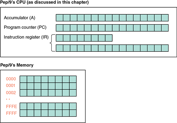
FIGURE 6.1 Pep/9’s architecture
Before we go on, let’s review some aspects of binary and hexadecimal numbers. The largest decimal value that can be represented in a byte is 255. It occurs when all of the bits are 1s: 11111111 in binary is FF in hexadecimal and 255 in decimal. The largest decimal value that can be represented in a word (16 bits) is 65,535. It occurs when all 16 bits are 1s: 1111111111111111 in binary is FFFF in hexadecimal and 65,535 in decimal. If we represent both positive and negative numbers, we lose a bit in the magnitude (because one is used for the sign), so we can represent values ranging from −7FFF to +7FFF in hexadecimal, or −32,767 to +32,767 in decimal.
This information is important when working with the Pep/9 machine. The number of bits we have available determines the size of the numbers we can work with.
Instruction Format
We’re almost ready to look at a subset of the instructions that the Pep/9 computer can execute. First, however, we need to examine the format of an instruction in Pep/9.
FIGURE 6.2(a) shows the format for an instruction in Pep/9. There are two parts to an instruction: the 8-bit instruction specifier and (optionally) the 16-bit operand specifier. So a Pep/9 instruction is either 1 byte or 3 bytes in length, depending on whether an operation specifier is needed.

FIGURE 6.2 Pep/9 instruction format
The instruction specifier indicates which operation is to be carried out, such as “add a number (the operand) to a value already stored in a register,” and how to interpret where the operand is. The operand specifier holds either the operand itself or the address of where the operand is to be found. Some instructions do not have an operand specifier.
The format of the instruction specifier is shown in FIGURE 6.2(b). In Pep/9, operation codes (called opcodes) vary from 4 bits to 8 bits long, but the only opcodes that we cover in this chapter are 4 bits long. The 5th bit is the register specifier, which will always be 0 in our examples to indicate the A register (the accumulator).
The 3-bit addressing mode specifier (shaded green) indicates how to interpret the contents of the operand specifier. If the addressing mode is 000, the operand specifier contains a data value to be used as the operand of the instruction. This addressing mode is called immediate (i). If the addressing mode is 001, the operand specifier contains a memory address. This addressing mode is called direct (d). (Other addressing modes also exist, but we do not cover them here.) See FIGURE 6.3. Memory addresses are shaded in orange; operands are shaded in gray.
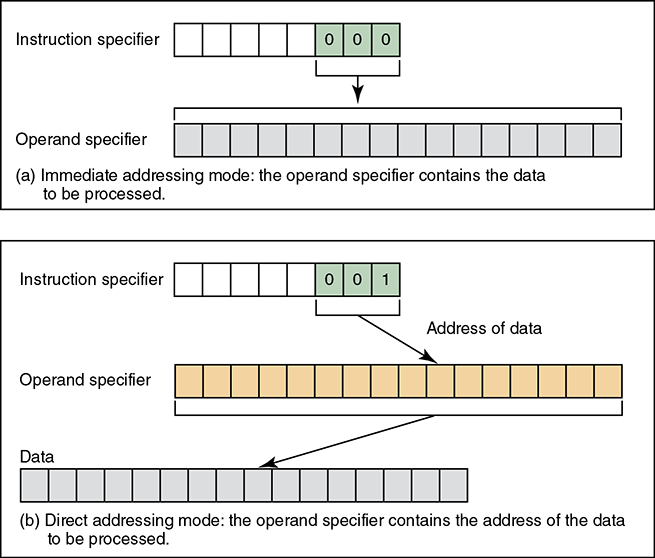
FIGURE 6.3 The difference between immediate addressing mode and direct addressing mode
Instructions that do not have an operand (data to be manipulated) are called unary instructions; they do not have an operand specifier. That is, unary instructions are only 1 byte long rather than 3 bytes long.
Some Sample Instructions
Let’s look at some specific instructions in isolation and then put them together to write a program. FIGURE 6.4 shows the operation code (or opcode) for the operations we are covering.
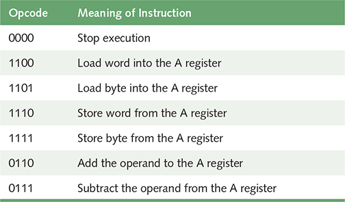
FIGURE 6.4 Subset of Pep/9 instructions
0000 Stop execution During the fetch–execute cycle, when the operation code is all zeros, the program halts. Stop is a unary instruction, with no operand specifier. The three rightmost bits in the instruction specifier, which would otherwise indicate the addressing mode, are ignored.
1100 Load word into the A register This instruction loads one word (two bytes) into the A register. The addressing mode determines where the word to be loaded is located. That is, the value to be loaded is either the actual value in the operand specifier or it is in the memory location of the address found in the operand specifier.
Let’s look at concrete examples of these options. Here is the first 3-byte instruction:


The addressing mode is immediate, meaning that the value to be loaded into the A register is in the operand specifier. The data is in the operand specifier, so it is shaded gray. When this instruction is executed, the contents of the second and third bytes of the instruction (the operand specifier) would be loaded into the A register (the accumulator). That is, the previous contents of the A register would be overwritten with the value 0307 (hex).
Here is another load instruction:


In this case, the addressing mode is direct, which means that the operand itself is not in the operand specifier; instead, the operand specifier holds the address (orange) of where the operand resides in memory. Thus, when this instruction is executed, the contents of location 001F would be loaded into the A register. This instruction loads a word (2 bytes), so when an address is used to specify the operand, as in this case, the address given is of the leftmost byte in the word. Thus the contents of adjacent locations 001F and 0020 are loaded into the A register. The contents of those memory locations are not changed.
1101 Load byte into the A register This instruction is like the load word instruction we just covered, but it loads only 1 byte instead of 2 bytes (one word).
If the addressing mode is immediate, the first byte of the operand specifier is ignored, and only the second byte of the operand specifier is loaded into the A register. If the addressing mode is direct, only 1 byte is loaded from the memory location specified instead of 2 bytes.
This instruction is useful when loading character data, as we’ll see in upcoming examples.
1110 Store word from the A register This instruction stores the entire contents of the A register into the memory location specified in the operand.


This instruction stores the contents of the A register into the word beginning at location 000A. It is invalid to use an immediate addressing mode with a store opcode because we cannot store the contents of a register into the operand specifier.
1111 Store byte from the A register This instruction is like the store word instruction we just covered, but it stores only 1 byte instead of 2 bytes (one word). Like the store word instruction, it does not support immediate addressing mode.
When this instruction executes, only the second byte of the A register (the accumulator) is stored in the address given in the operand specifier. The first 8 bits of the accumulator are ignored.
Like the load byte instruction, this instruction is useful when processing character data. We’ll explore character I/O after discussing the last two instructions in our list.
0110 Add the operand to the A register Like the load operation, the add operation uses the addressing mode specifier, giving alternative interpretations. Here’s an example of the first alternative, using immediate addressing mode:


When this instruction is executed, the value in the operand specifier (020A in hex) is added into the contents of the A register. Now let’s look at an add operation that uses direct addressing mode:


Because the address mode specifier is direct, the contents of the operand specifier are treated as an address (location 020A). When the instruction executes, whatever value that is stored at that location in memory is added into the A register.
0111 Subtract the operand from the A register This instruction is just like the add operation, except that the operand is subtracted from the A register rather than added. As with the load and add operations, both immediate and direct addressing modes are supported.
Input and Output in Pep/9
The Pep/9 system simulates the ability to read character input from the keyboard and write character output to the screen (the terminal window). Although this process is simulated, like everything else in the Pep/9 virtual machine, it follows common computer systems design techniques.
In the case of input and output (I/O), the design principle followed is called memory-mapped I/O, which wires input and output devices to specific, fixed addresses in main memory. In Pep/9, the input device is at address FC15 and the output device is at address FC16.
To read a character from the input device, you load the value from the input device address into the accumulator (A register). To write a character to the output device, you load the character value into the accumulator and then store the value of the accumulator to the output device address. These operations are specific examples of the load byte and store byte instructions discussed earlier.
Pep/9 uses the ASCII character set (discussed in Chapter 3) to represent characters. Each ASCII character is represented by a single byte, so we use the load byte and store byte operations to perform character I/O in Pep/9 instead of the versions of those instructions that manipulate full words.
We’ll see this I/O processing in action in the upcoming examples.