6.4 Assembly Language
As we pointed out in Chapter 1, the first tools developed to help the programmer were assembly languages. Assembly languages assign mnemonic letter codes to each machine-language instruction. The programmer uses these mnemonics in place of binary or hex digits. Programming using mnemonics instead of directly in machine language makes the programmer more efficient and the process less error prone. After all, it’s much easier to remember the mnemonic ADDA (to add a value to the A register) than it is the opcode 0110.
Ultimately, though, every program that is executed on a computer eventually must be in the form of the computer’s machine language. So, we use a program called an assembler to read each of the instructions in mnemonic form and translate it into the machine-language equivalent, as shown here:

Because each type of computer has a different machine language, there are as many assembly languages and translators as there are types of CPUs.
Pep/9 Assembly Language
The goal of this section is not to make you an assembly-language programmer, but rather to have you appreciate the advantages of assembly-language programming over machine coding. With this goal in mind, we cover only a few of Pep/9’s assembly-language features here. In Pep/9’s assembly language, the operand is specified by “0x” and the hexadecimal value, then a comma followed by the addressing mode (the letter “i” for immediate or “d” for direct).
| Mnemonic | Operand, Mode | Meaning |
STOP |
Stop execution | |
LDWA |
0x008B,i |
Load word 008B into accumulator |
LDWA |
0x008B,d |
Load word located at 008B into accumulator |
LDBA |
0x008B,i |
Load byte 008B into accumulator |
LDBA |
0x008B,d |
Load byte located at 008B into accumulator |
STWA |
0x008B,d |
Store word from accumulator to location 008B |
STBA |
0x008B,d |
Store byte from accumulator to location 008B |
ADDA |
0x008B,i |
Add 008B into accumulator |
ADDA |
0x008B,d |
Add word located at 008B into accumulator |
SUBA |
0x008B,i |
Subtract 008B from accumulator |
SUBA |
0x008B,d |
Subtract word located at 008B from accumulator |
There are two mnemonics used to load a value into the accumulator: LDWA to load a word and LDBA to load a byte. Both can be used with immediate addressing (i), which loads the value of the operand, or with direct addressing (d), which treats the operand as an address and loads the value found at that memory location.
There are two mnemonics for storing a value from the accumulator to a memory location, one for storing a word and one for storing a byte. As with the machine-language versions of these operations, they do not support immediate addressing mode.
The add and subtract operators support both immediate and direct addressing modes, and always operate on a full word.
In addition to regular instructions, assembly-language programming also allows assembler directives, which are instructions to the assembler itself. They are sometimes referred to as pseudo-operations. Here are some of Pep/9’s assembler directives:
| Pseudo-op | Operand | Meaning |
.END |
Signals the end of the assembly-language program | |
.ASCII |
"bananax00" | Represents a string of ASCII characters |
.WORD |
0x008B | Reserves a word in memory and stores a value in it |
.BLOCK |
number of bytes | Reserves a particular number of bytes in memory |
Let’s look at an assembly-language version of the program we wrote that printed the word “Hi”:
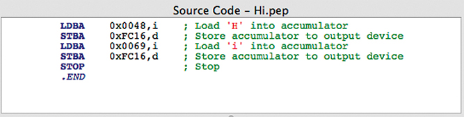
This code is written into the Source Code window of the Pep/9 simulator. The Pep/9 assembler ignores any characters after a semicolon. This allows the programmer to put in comments, which are text written for a human reader of the program, explaining what is happening. It’s up to the programmer to decide which comments to include. Not every line needs a comment, but they are often helpful.
Of course, this source code in assembly language must be translated into machine code (or object code) before it can be executed. The Build > Assemble menu option runs the assembler on the source code. If there are no errors, the object code is displayed as well as an assembly code listing, which is a nicely formatted version of the program that includes the memory addresses and the object code:
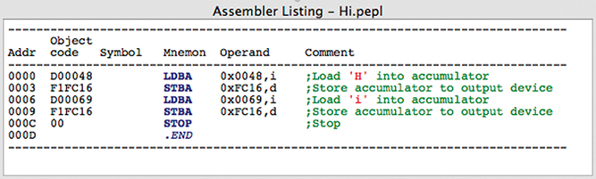
For convenience, the Pep/9 simulator also provides the Build > Run Source menu option, which will assemble the source code into object code and then execute it automatically (instead of making you do those as separate steps). There is also a Run Source button you can press.
This program uses immediate addressing to load the characters, which is how we did it when we wrote this same program directly in machine language. Before moving on, compare it to the following version of this program, which uses direct addressing:

In this version, the characters to be printed are stored in memory using the .ASCII assembler directive. As the listing shows, the load instructions access memory locations 000D and 000F, which correspond to the stored data.
Numeric Data, Branches, and Labels
You may have noticed that we never wrote a program directly in machine language that performed numeric calculations. That’s because output for Pep/9 machine language is only defined for individual characters. If we had done arithmetic, we would have had to convert the input characters to numbers and vice versa to produce the output. It can be done, but that makes for a much longer machine-language program.
With the Pep/9 assembly language, additional instructions are available that perform input and output (I/O) with numbers and whole strings of characters. These instructions actually are implemented by the operating system.
In addition, upcoming examples will make use of branch instructions, which let the programmer decide which instruction to execute next. Here are some additional assembly-language instructions:
| Mnemonic | Operand, Mode | Meaning |
DECI |
0x008B,d |
Read a decimal number and store it into location 008B |
DECO |
0x008B,i |
Write the decimal number 139 (8B in hex) |
DECO |
0x008B,d |
Write the decimal number stored at location 008B |
STRO |
0x008B,d |
Write the character string stored at location 008B |
BR |
0x001A |
Branch to location 001A |
BRLT |
0x001A |
Branch to location 001A if the accumulator is less than zero |
BREQ |
0x001A |
Branch to location 001A if the accumulator is equal to zero |
CPWA |
0x008B |
Compare the word stored at 008B with the accumulator |
The DECI instruction stands for Decimal Input. It reads a decimal value (a number in base 10) from the input device and stores it into the location specified by the operand. The number can be made up of multiple digits—the instruction takes care of converting the typed characters into a number. Immediate addressing mode is not allowed for this instruction.
The DECO and STRO instructions cause data to be written to the output device. The DECO instruction outputs the specified value as a decimal number. Either immediate or direct addressing can be used. The STRO instruction is used for printing a full string of characters (perhaps a string stored in memory using the .ASCII directive).
The branch instruction BR is called an unconditional branch and causes the program counter (the register used to determine which instruction is fetched next) to be set to the memory address in the operand. A branch operation interrupts the normal linear flow of a program by “jumping” to another place in the program.
The BRLT and BREQ instructions cause the program to branch only if certain conditions are true, namely that the value in the accumulator is less than zero or equal to zero, respectively. Otherwise, the next instruction is executed as it normally would be.
Finally, the CPWA instruction compares the operand to the value that’s in the accumulator. More precisely, it subtracts the operand from the current value in the accumulator and stores the result in the accumulator. At that point, the accumulator will contain zero if the values are equal, or a negative value if the operand is greater than the current accumulator value. Then the BRLT or BREQ instructions can be used to make an appropriate decision.
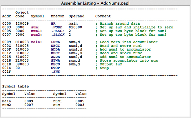
Let’s look at an example that reads two numbers from the user, adds them, and prints the result. To accomplish this, we’ll need places in memory to store the two values and the sum. Although they could be stored after the program, memory used for data in an assembly-language program is often reserved before the program:

This program makes use of labels on some of the assembly directives and instructions. Labels are put at the beginning of the line, followed by a colon. Once labeled, the data or instruction at that location can be referred to by its label instead of its specific memory address. This makes the program much easier to follow.
In this example, the first line of code is a branch instruction that jumps over the data to the first real line of the program, labeled main. The program statements execute from there until the STOP instruction is reached.
The data at the beginning of the program is made up of a word labeled sum, which is initialized to zero, and two blocks (each 2 bytes long) labeled num1 and num2 that will hold the two numbers to add.
The program reads the first number, storing it in num1, and then adds it to the accumulator. It then does the same for num2. The sum of the two numbers is now in the accumulator, which is stored back into the memory location labeled sum. Finally, the sum is written to the output device.
When the program is executed, the user types the two numbers in the Terminal window, and the program prints the sum:

The labels and their corresponding addresses are shown in a symbol table after the code listing:
Here is a variation on the AddNums program, which prints an error message if the sum of the two numbers is negative:

This version has another label for printing the error message. A BRLT instruction is used to branch to the error message only if the accumulator (the sum) contains a negative number. After printing the error message, an unconditional branch is used to jump to the end of the program, labeled finish.
Here is a sample output when the two input values add to a negative number:

Loops in Assembly Language
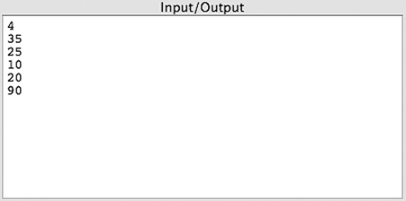
What if we wanted to read and sum three values? 10 values? 50? Let’s rewrite our AddNums program yet again to use a loop, which is a section of code the program executes multiple times based on some criteria:
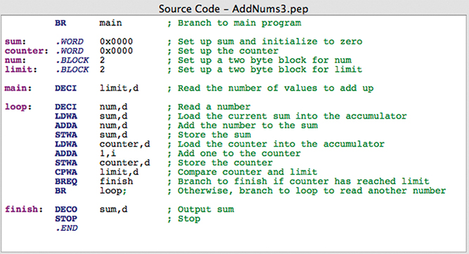
This program first reads a number from the user that specifies how many values will contribute to the sum. It also uses a counter, which starts at 0. Then we enter the loop, which reads a value and adds it to the sum. Each time through the loop, we add 1 to the counter and check it to see if we have reached the limit using a BREQ instruction. If so, we break to the end of the program. If not, we go back to the top of the loop to process another value.
Here is a sample run that reads and sums four numbers: 35 + 25 + 10 + 20 = 90.