
Note 44. The z Transform
The z transform is a mathematical tool that plays a role in the analysis of discrete-time systems similar to the role played by the Laplace transform in the analysis of lumped-parameter continuous-time systems. It has a place in the theoretical exploration of all linear shift-invariant discrete-time systems, but in practice, the z transform (and its relationship to the Laplace transform) is most commonly used in the design of IIR filters. In fact, some authors, such as Lyons [1], discuss the z transform only in conjunction with IIR filter design.
Sometimes, pole and zero locations (which are features obtained from the z transform) are used as visualization aids to provide insight into the behavior of adaptive filters as their coefficients evolve over time or converge to different values as a function of SNR. An example of such use is provided by Kay in [2].
The z transform can be defined in either a one-sided (unilateral) or two-sided (bilateral) form:
44.1
![]()
44.2
![]()
where z is a continuous complex-valued variable. Different authors follow different conventions with respect to which form they consider to be the default when “one-sided” or “two-sided” is not specifically called out. The two-sided transform is the form most often used in DSP applications. When x[n] is a causal sequence, the two forms are equivalent.
Key Concept 44.1. Role of the z Transform in Digital Filter Analysis
• The z transform of a digital filter’s unit sample response is called the system function and is denoted H(z). In general, a linear shift-invariant digital filter has a system function that is a ratio of polynomials in z:
H(z) = P(z)/Q(z)
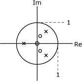
• Roots of these polynomials are often plotted in the complex z plane to help visualize various aspects of the filter’s behavior. Roots of the numerator are called zeros, and are typically plotted using small circles (o). Roots of the denominator are called poles, and are typically plotted using small multiplication signs (×).
44.1. Region of Convergence
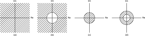
The series represented by Eq. (44.2) does not always converge for every possible value of z. The portion of the z plane for which the series does converge is called the region of convergence (ROC). Whether or not the series converges depends upon the magnitude of z rather than on the specific complex value of z. Therefore, ROC boundaries are always defined by circles centered at the origin of the z plane. There are four major configurations for the ROC, as depicted in Figure 44.1. Depending upon whether z = 0 and |z| = ∞ are included in the ROC, there are a total of nine specific variations on the four basic configurations:
• entire z plane
• entire z plane except for z = 0
• entire z plane except for |z| = ∞
• entire z plane except for z = 0 and |z| = ∞
• interior of circle
• interior of circle except for z = 0
• exterior of circle
• exterior of circle except for |z| = ∞
• annulus
Figure 44.1. Possible configurations for region of covergence: (a) the entire z-plane, (b) exterior of a circle, (c) interior of a circle, and (d) an annulus
As summarized in Table 44.1, the ROC for any particular z transform depends upon the characteristics of the sequence x[n].
Table 44.1. ROC configurations corresponding to various constraints placed on the sequence x[n]
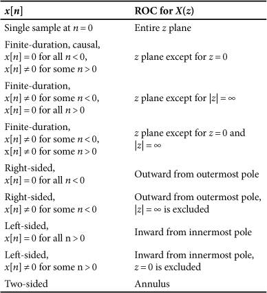
Table 44.2. Bilateral z-Transform Pairs
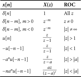
Table 44.3. Unilateral z-Transform Pairs
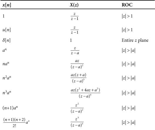
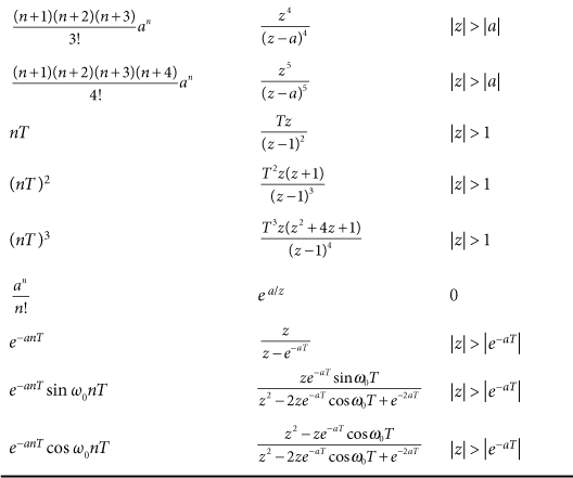
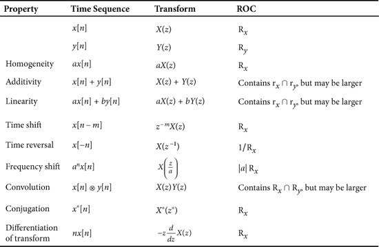
Table 44.4. Properties of the z Transform
References
1. R. Lyons, Understanding Digital Signal Processing, Prentice Hall, 1996.
2. S. M. Kay, “The Effects of Noise on the Autoregressive Spectral Estimator,” IEEE Trans. Acous. Speech and Signal Proc. ASSP, vol. 27, no. 5, Oct. 1979, pp. 478–485.