
Chapter 15
Patterning and Mirroring Components
In SolidWorks assemblies, the word component can refer to either parts or subassemblies. Component patterns can be patterns of parts, subassemblies, or combinations of parts and subassemblies.
Component Patterns
Component patterns come in several varieties, as shown in Figure 15.1. Of these, only the Linear and Circular patterns do not require references outside of the assembly, which is to say that most component patterns are going to require some sort of external (in-context) reference. These references can be sketches or pattern features from parts.
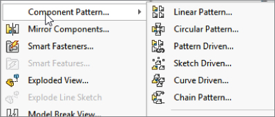
FIGURE 15.1 Types of component patterns in SolidWorks
Mirroring components in assemblies is far more complex than mirroring features in parts. SolidWorks provides options for mirrored parts, mirrored positions, left-hand and right-hand versions of parts, and mirroring parts and subassemblies within top-level assemblies.
Using Local Component Patterns
Local component patterns are limited to Linear and Circular patterns; SolidWorks assemblies do not offer all the options available for patterning features in a part, such as table-driven and fill pattern. The Linear pattern directions work just like the Linear Pattern feature in parts and must reference a line, axis, edge, plane, planar face, and so on to establish the direction. Remember, it is best if possible to reference items close to home in the local assembly file rather than select something external from part geometry. In an assembly, this means that the pattern feature uses either local reference geometry from the assembly (such as axes, planes, or assembly sketches) or model geometry from a part (such as solid or surface edges, sketches, or reference geometry). Keep this in mind if you are concerned about external or circular references. By using references belonging to the assembly rather than to parts, you avoid some common referencing pitfalls.
Creating Local Pattern References
It is best to use references that are not dependent on part geometry. Remember that when part geometry is used as an assembly pattern reference, the parts must be solved first (sketches and features rebuilt), then the mates must be solved (to position the parts), then any in-context references must be solved (which may change the part geometry), and then any assembly features or component patterns must be solved. As a result, it is best practice to use assembly reference geometry or assembly sketches without references as pattern direction references. The assembly sketches should sit at the top of the assembly FeatureManager to ensure that they do not pick up references from the history-based features in the design tree (mated components, patterns, assembly features, and so on).
When a local pattern really requires a reference from a part, you have no alternative. However, if you can avoid this situation by using a sketch assembly skeleton to which the parts are mated and used for the pattern references, then you should do so. At all costs, you should avoid using in-context features, assembly reference geometry that is dependent on part geometry, and assembly features (other than sketches) for the local pattern reference.
USING THE INSTANCES TO SKIP OPTION
The Instances To Skip option for component patterns, shown in Figure 15.2, works just like the equivalent option for features. Click the dots in the graphics window to toggle each instance of the pattern. On the screen, the instances to keep use pink dots and the instances to skip use orange dots. The colors are almost indistinguishable at a relatively wide spacing.
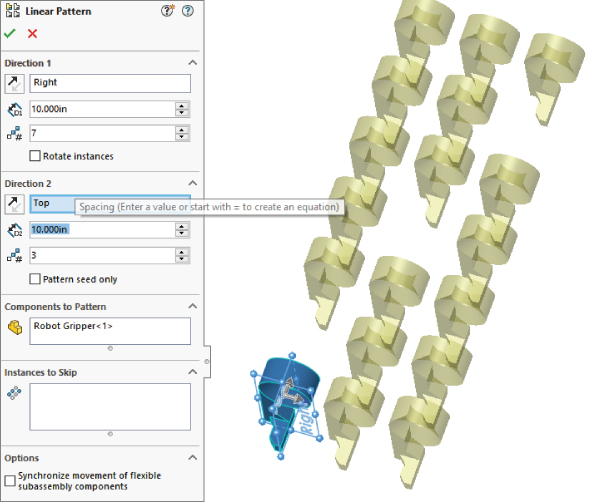
FIGURE 15.2 The Instances to Skip option
PATTERNING THE SEED ONLY
All the aspects of the interface should be familiar to you, such as the direction, instances, and spacing. The Pattern Seed Only option is used in feature patterns.
This option is designed to allow you to create a single pattern in two directions that are separated by 180 degrees, where the internal instances do not overlap one another. For example, if you take a basic two-directional pattern and change the angle between the directions so that they are antiparallel (parallel but going in opposite directions), then all the component instances that were between the two legs of the L created by the two directions will overlap one another. One flaw in this feature is that it will not allow you to select the same linear entity (for example, an axis) for both directions, so that, as in the example in Figure 15.3, you have to find two separate entities (in this case, an axis and an edge) that are parallel. The assembly used for this image is available in the download material for Chapter 15 as Pattern Seed Only.sldasm. The assembly template with the axes in it is in the MBD folder and is named AxesAssembly.asmdot.
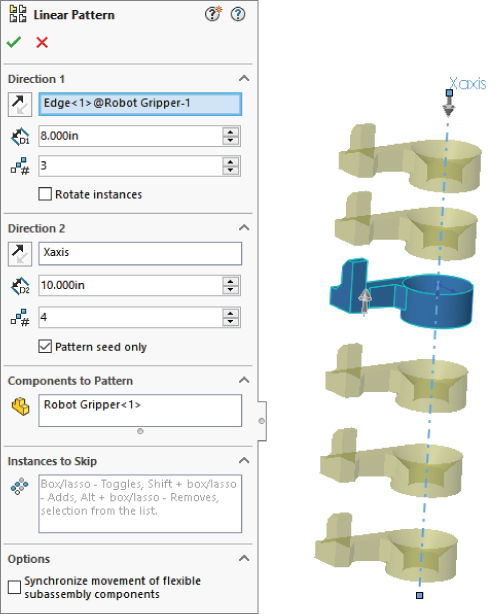
FIGURE 15.3 Use the Pattern Seed Only option for two-directional patterns.
Using Mirror Components
![]() The Mirror Components tool leaves a feature in the assembly tree just as pattern features do. It gives you the option to align each mirrored part and decide which parts require opposite-handed versions and which can just use the original in a mirrored location. Figure 15.4 shows the PropertyManager for this assembly feature. Notice that the mechanism linkages require only the identical part in a mirrored position. The brake lever assembly, however, requires opposite-handed parts in a mirrored position. To examine this assembly more closely, open
The Mirror Components tool leaves a feature in the assembly tree just as pattern features do. It gives you the option to align each mirrored part and decide which parts require opposite-handed versions and which can just use the original in a mirrored location. Figure 15.4 shows the PropertyManager for this assembly feature. Notice that the mechanism linkages require only the identical part in a mirrored position. The brake lever assembly, however, requires opposite-handed parts in a mirrored position. To examine this assembly more closely, open Mirrored Components.sldasm.
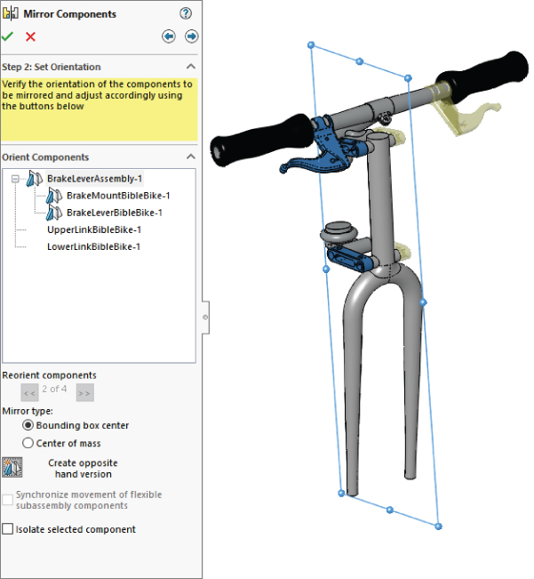
FIGURE 15.4 Mirroring components of an assembly with the Mirror Components tool
The workflow to mirror components in the assembly has three steps, the second of which is shown in Figure 15.4:
- Selections. Select the parts and subassemblies that you want to mirror, along with the plane about which you want to mirror the components.
- Set Orientation. Identify the components that must have opposite-hand versions; for the others, you can toggle through the available options for placement.
- Opposite-Hand Versions. For the parts that need opposite-hand versions, you can assign them to use new parts or derived configurations.
The first step should be self-explanatory. Just select the parts and plane as you would in other situations. You move between the steps by clicking the arrows in blue circles in the upper-right corner of the Mirror Components PropertyManager.
SETTING THE ORIENTATION
![]() The second step requires some explanation. In the PropertyManager labeled Step 2: Set Orientation (refer to Figure 15.4), notice that there are some mirror symbols in front of the BrakeLeverAssembly and BrakeMountBibleBike selections in the Orient Components panel. This means that these documents must have mirrored instances. You control this option by selecting the part or assembly in the Orient Components list box and then clicking the Create Opposite Hand Version button at the bottom of the PropertyManager.
The second step requires some explanation. In the PropertyManager labeled Step 2: Set Orientation (refer to Figure 15.4), notice that there are some mirror symbols in front of the BrakeLeverAssembly and BrakeMountBibleBike selections in the Orient Components panel. This means that these documents must have mirrored instances. You control this option by selecting the part or assembly in the Orient Components list box and then clicking the Create Opposite Hand Version button at the bottom of the PropertyManager.
Another thing you need to do in this second step is correctly orient parts that do not require an opposite-hand version. To do this, select a part in the Orient Components list box, such as the GripsBibleBike part, and click through the double-arrows just below the selection box. In Figure 15.4, the message “2 of 4” is grayed out because a part that requires an opposite hand is selected. When you click the arrows, the part repositions in another possible mirrored position and orientation.
The Mirror Type options Bounding Box Center and Center Of Mass determine how the mirrored component is positioned. If you create an opposite-hand version, the position is automatically determined, so the options do not make any difference.
When you mirror a component, you first have to consider the mirror plane, and then you have to consider the pivot orientation of the component once its position is determined. The Reorient Components control in this case gives you four different options for the pivot orientation. Notice that some of the options change if you use Bounding Box rather than Center of Mass. Essentially, two mirrors are occurring. The first is the mirror about the selected mirror plane, and the second is the mirror about either the Bounding Box Center or the Center Of Mass. It's not critical, as long as the components wind up in the correct position and orientation. Use the Reorient Components options to determine that.
Figure 15.5 shows all of the combinations of the Reorient Components 1 through 4 for both Bounding Box Center (left) and Center Of Mass (right) mirror types.
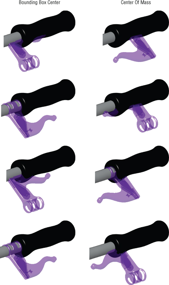
FIGURE 15.5 The mirror results of the Bounding Box Center and Center Of Mass options
The correct result should be obvious, but there could be more than one correct result.
CREATING OPPOSITE-HAND VERSIONS
In the third step, in the Opposite Hand Versions panel of the PropertyManager, only the documents that must be changed are listed. In this case, the brake lever assembly is made of two parts: the lever part can be used in both left-hand and right-hand versions, but the mount must have two different versions of the part. This means the assembly must also have two versions.
This Mirror Components functionality is fantastic, involving a well-thought-out process. To make the mirrored versions, you have the option to create new files or to create a derived configuration within the existing files.
As you are setting up these options, SolidWorks displays a preview of the result in the graphics window. The preview parts are transparent and may be a pale yellow. (You may want to change them to a darker orange color at Tools ➢ Options ➢ Colors ➢ Temporary Graphics, Shaded.) You can see how the parts are oriented and can immediately fix any problems that arise. With larger assemblies and larger sets of mirrored components, the visualization may be more difficult, but the process demonstrated here on these parts works and gives a complete set of options as you work through the process of mirroring parts and assemblies within the top-level assembly.
COMPLETING THE TASK
When you are finished with the task, you can click the green checkmark icon. In this case, SolidWorks displays a message that one of the mates in the mirrored assembly could not be duplicated, as shown in Figure 15.6. After testing the motion of the fork linkage, this missing mate does not appear to affect the assembly.
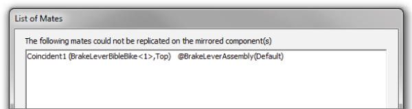
FIGURE 15.6 A mate is not created as the mirroring task is completed.
The Mirror Component feature leaves a marker in the assembly FeatureManager after the Mates folder. In Figure 15.7, notice that the BrakeLeverAssembly and BrakeMountBibleBike documents use a MirrorDefault configuration, as was established while mirroring the assembly and parts.
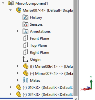
FIGURE 15.7 Examining the list of mirrored components
Using Feature-Driven Component Patterns
By their very nature, feature-driven component patterns defy some of the best practice suggestions in this book. This is because the pattern is driven by part geometry, and the part must first be solved (by solving features internal to the part) and then placed (by solving mates); only then can the feature-driven pattern be solved. Nevertheless, you should use feature-driven patterns instead of local patterns when available because of the parametric link. Parametric associativity is, after all, one of the main benefits that SolidWorks offers.
Figure 15.8 shows the PropertyManager interface for a feature-driven component pattern. This sample file is with the download material for this chapter under the name Feature Driven Pattern.sldasm.
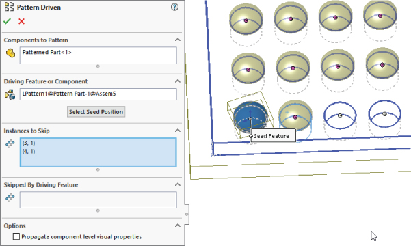
FIGURE 15.8 The feature-driven Component Pattern interface
You can nest feature-driven component patterns such that one component pattern is patterned by another component pattern, just as you do using feature patterns. The second pattern can be a local pattern or a feature-driven pattern.
In the case shown in Figure 15.8, I used the Instances To Skip option, selecting multiple adjacent instances with a box or lasso.
Creating a Chain Pattern
We have been using a bicycle as an example file for much of this book, so using the Chain Pattern feature seems appropriate here.
Start with a sketch of the chain line, which SolidWorks refers to as the path. The chain of a real bicycle would flex; but for SolidWorks purposes, your chain line must be planar. The sketch must also be clean, with no gaps or overlaps, and it must be a single continuous loop where all the entities are tangent end-to-end. Also, in this case, you may notice that the chain interferes with the drive-side chain stay when in the highest gear, but this is left for you to work out as a design exercise. Figure 15.9 shows the sketch for the chain path.
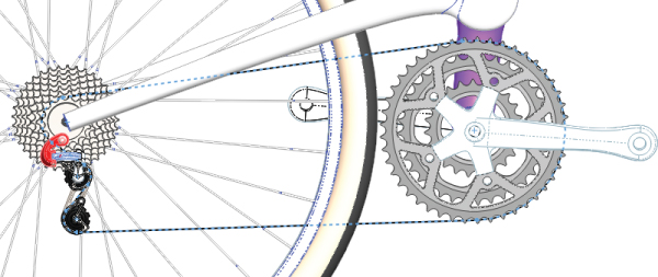
FIGURE 15.9 Create a sketch for the chain line.
Next, you need to create the links in your chain. Bicycle chains are made of inner and outer links. Other types of chain may have just one element. You may choose to model the chain links another way because of the way the chain is manufactured or assembled, but Figure 15.10 shows how I chose to model the chain to work best with the SolidWorks Chain Pattern feature.
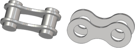
FIGURE 15.10 Chain links are made of separate parts.
Next, the links need to be placed in the assembly. You may choose to have a separate assembly for the chain. The chain shows up in the assembly where it is created as a feature, with several part instances under it, just like a pattern. The links will be placed on the chain path sketch by the Chain Pattern feature, so you don't need to mate them there yourself. The Chain Pattern interface walks you through the process, shown in Figure 15.11.
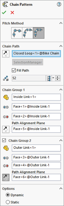
FIGURE 15.11 The Chain Pattern PropertyManager interface
If you choose the third option in the Pitch Method, which is Connected Links, you need to have two separate link parts, or at least a single link with alternating position. The Connected Links Pitch Method activates the second chain group. Use the Path Alignment Plane to make sure the correct faces of the links are mated.
To get a chain pattern to be perfectly end-to-end, you have to work with the path sketch length and adjust it until the first and last links connect.
The chain pattern can help you get an idea of how long your actual chain needs to be, as well as produce a looks-like visual for your drawings. For situations where your chain needs to be nonplanar, such as the actual application of a bicycle chain, that is something you can't simulate with this tool. The chain pattern helps you identify that the design of the chain stay on this bike needs to be altered to avoid rubbing on the chain in the highest gears.
The Dynamic and Static options allow or disallow motion, respectively. The advantage of disallowing motion would be that you would avoid calculating all the associated mates.
Once the pattern is created, all the necessary links components are kept under the Chain Pattern feature, as partially shown in Figure 15.12.
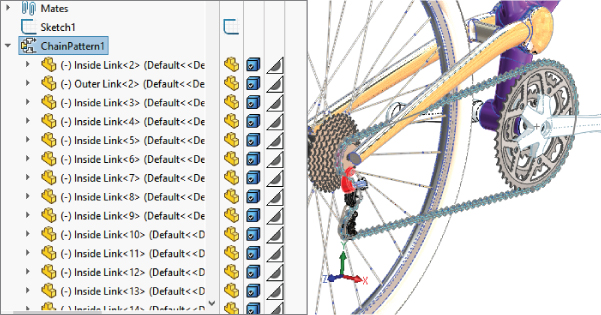
FIGURE 15.12 The Chain Pattern feature in the assembly FeatureManager tree
Understanding Other Pattern Options
SolidWorks provides additional options to help you work with patterns. These options can help you with component organization and visualization, which are always key elements when you are working in an assembly.
Figure 15.13 shows the RMB menu for a component pattern. The selections relevant to patterns available on the RMB menu are as follows:
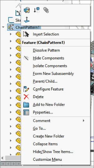
FIGURE 15.13 The component RMB menu
- Dissolve Pattern: The Dissolve Pattern option removes the component instances from the pattern feature and puts them in the main part of the assembly FeatureManager. The components just become normal components in the assembly without the intelligence of the pattern feature placing them. The components are left in the assembly without any mates and are simply floating in position.
- Add To New Folder: You can add patterns to folders. If you have a list of patterns at the end of an assembly, it may make sense to group them into related folders for the purpose of organization. This is the same as using folders for features, mates, or components.
- Component pattern display options: You can change the appearance of individual component pattern instances either individually or collectively as a pattern feature using the Display pane, shown in the four columns to the right of the FeatureManager in Figure 15.11. Remember you can access the Display pane quickly by pressing the F8 key.
- Component patterns and configurations: Individual instances of the component pattern also enable you to control configurations. After you create the pattern, you can select individual instances and change their configurations. This can be extremely useful if you have a mechanism subassembly shown in various positions—for example, patterned around an indexing dial.
Tutorial: Creating Component Patterns
To learn how to create component patterns, follow these steps:
- Open a new assembly. Create a new 3D sketch, and draw three lines from the origin out at odd angles so that they do not pick up horizontal or vertical automatic relations. Draw two of the lines; then rotate the view, press the Tab key, and draw the third line.
- Apply sketch relations such that each line lies on a plane: one line on the Front, one on the Top, and one on the Right. Make sure none of the lines overlap.
- Click Close to exit the sketch when you are finished.
- Open the
Pattern Part.sldprtpart from the download materials. This part already contains several features that you can use to practice working with feature-driven component patterns. - Insert the part into the new assembly created in step 1. Locate the part at the assembly origin such that the part origin matches the assembly origin.
- Place the part called
Patterned Part.sldprtin the assembly. - Place the small part on the original feature of the rectangular pattern of round holes near the origin, as shown in Figure 15.14. All the original features are colored red. Remember that Alt+dragging the circular edge on the flat side of the part enables you to SmartMate the part to the round holes. SmartMate cannot help you with the rectangular or hex holes. For them, it may be best to show the sketch for the holes and place the part with respect to the sketch entities.
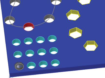
FIGURE 15.14 Placing the patterned part
- Create feature-driven patterns (Insert ➢ Component Pattern ➢ Feature Driven). Try to use each of the patterns from the pattern part. For each new pattern, make a copy of the patterned part and place it in one of the holes. Remember to use the Select Seed Position option to pick a feature-pattern instance instead of the original feature.
- After you have created a few feature-driven patterns and have a better understanding of how it is done, right-click the top level of the assembly FeatureManager and select Collapse Items (near the bottom of the menu). The point of this example is simply to practice placing a part and patterning it with an existing feature pattern. The assembly will look like Figure 15.15 when you are done.
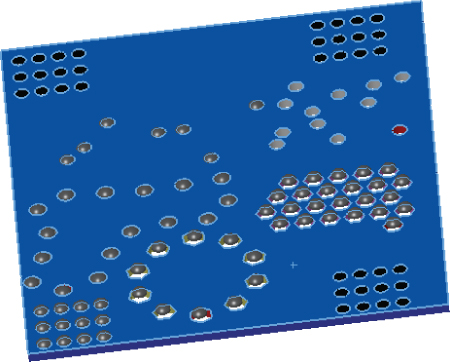
FIGURE 15.15 Several feature-driven patterns
- Create a local pattern (Insert ➢ Component Pattern ➢ Linear Pattern). Select one of the 3D sketch lines drawn in step 1 as a pattern direction.
- Highlight the Components To Pattern selection box. Select the first part in the FeatureManager and then Shift+select the last pattern feature. This patterns everything in the assembly.
- Make the spacing 4 inches with three instances.
- Create a second direction using another of the sketch lines with 6-inch spacing and four instances.
- Notice how the preview shows 12 instances of the patterned assembly. Select the option for Pattern Seed Only, and see how the preview changes to seven instances. Figure 15.16 shows this difference. Click OK to accept the feature.
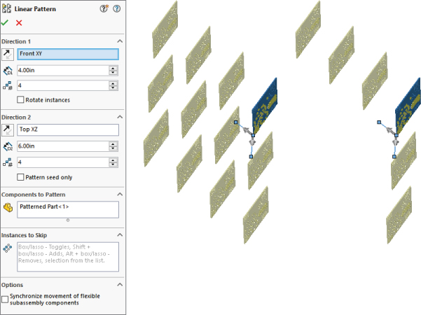
FIGURE 15.16 Two direction patterns, one with and one without the Pattern Seed Only option
The Bottom Line
Performance and best practice are both issues that require compromise. Patterns can cause a performance reduction because of the nature of the references. However, they can also improve performance because the need for extra mates is reduced, and it is easier to simplify the assembly by suppressing the pattern feature.
Feature-driven patterns are driven by feature patterns and transgress best practice suggestions, but they also add a parametric link, which updates the component pattern automatically. In addition, they offer many more options that are driven by the pattern options available to features in a part.
- Master It Create a new part with multiple features, one of them being a hole of a 0.2” diameter. Make a pattern of the hole feature. Put this new part into an assembly with the part called Patterned Part.sldprt. Use the Patterned Part.sldprt in a pattern driven pattern, using the pattern of holes from the new part you just created.
- Master It Create a new assembly from a template that uses axes for the main X-, Y- and Z-directions. There is one called
AxesAssembly.asldotin the MBD template folder. Insert an assembly such as one of the sample bicycle wheel assemblies, and pattern it in three directions. - Master It Create a new assembly, and open a new sketch in the assembly. Create a closed-loop sketch that is bigger than 6 inches on a side where all of the elements are tangent (no small fillets or tangent arcs between lines).
Create a curve-driven pattern that uses the
Patterned Part.sldprtto be patterned in two directions based on elements in the sketch.Copy the sketch to a perpendicular plane in the assembly and create a chain pattern using the same part and the Distance Pitch method in the Chain Pattern PropertyManager.