The most important integrated circuit in any computer is the central processing unit (CPU). The processing of a CPU is discussed in the next chapter, but it is important to recognize at this point that the CPU is, in one sense, merely an advanced circuit with input and output lines.
Each CPU chip contains a large number of pins through which essentially all communication in a computer system occurs. This communication connects the CPU to memory and I/O devices, which are themselves, at fundamental levels, advanced circuits.
The explanation of CPU processing and its interaction with other devices takes us to another level of computer processing, sometimes referred to as component architecture. Although it is still primarily focused on hardware, computer component architecture applies the principle of abstraction yet again, allowing us to temporarily ignore the details of the gates and circuits discussed in this chapter and bringing us ever closer to a complete understanding of computer processing.
SUMMARY
In this chapter we discussed how a computer operates at its lowest level by controlling the flow of electricity. Because we are dealing with digital computers that use binary information, we concern ourselves with only two voltage ranges, which we interpret as binary 1 or 0. The flow of electricity is guided by electronic devices called gates, which perform basic logical operations such as NOT, AND, and OR. A gate is created by using one or more transistors, an invention that revolutionized computing.
Gates can be combined into circuits, in which the output of one gate serves as an input to another gate. By designing these circuits carefully, we can create devices that perform more complex tasks, such as adding, multiplexing, and storing data. Collections of gates, or complete circuits, are often embedded into a single integrated circuit, or chip, which leads to the concept of a central processing unit (CPU).
For Exercises 1–17, mark the answers true or false as follows:
True
False
1. Logic diagrams and truth tables are equally powerful in expressing the processing of gates and circuits.
2. Boolean expressions are more powerful than logic diagrams in expressing the processing of gates and circuits.
3. A NOT gate accepts two inputs.
4. The output value of an AND gate is 1 when both inputs are 1.
5. The AND and OR gates produce opposite results for the same input.
6. The output value of an OR gate is 1 when both inputs are 1.
7. The output of an OR gate is 0 when one input is 0 and one input is 1.
8. The output value of an XOR gate is 0 unless both inputs are 1.
9. The NOR gate produces the opposite results of the XOR gate.
10. A gate can be designed to accept more than two inputs.
11. A transistor is made of semiconductor material.
12. Inverting the output of an AND gate is equivalent to inverting the individual signals first, then passing them through an OR gate.
13. The sum of two binary digits (ignoring the carry) is expressed by an AND gate.
14. A full adder takes the carry-in value into account.
15. A multiplexer adds all of the bits on its input lines to produce its output.
16. Integrated circuits are classified by the number of gates contained in them.
17. A CPU is an integrated circuit.
For Exercises 18–29, match the gate with the description of the operation or the diagram.
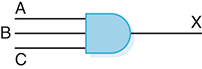
AND
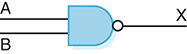
NAND
XOR
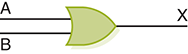
OR
NOR
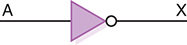
NOT
18. Inverts its input.
19. Produces a 1 only if all its inputs are 1 and a 0 otherwise.
20. Produces a 0 only if all its inputs are 0 and a 1 otherwise.
21. Produces a 0 only if its inputs are the same and a 1 otherwise.
22. Produces a 0 if all its inputs are 1 and a 1 otherwise.
23. Produces a 1 if all its inputs are 0 and a 0 otherwise.
24.
25.
26.
27.
28.
29.
Exercises 30–73 are short-answer or design questions.
30. How is voltage level used to distinguish between binary digits?
31. Distinguish between a gate and a circuit.
32. What are the three notational methods for describing the behavior of gates and circuits?
33. Characterize the notations asked for in Exercise 32.
34. How many input signals can a gate receive, and how many output signals can a gate produce?
35. Name six types of gates.
36. Give the three representations of a NOT gate and say in words what NOT means.
37. Give the three representations of an AND gate and say in words what AND means.
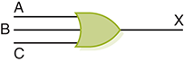
38. Give the three representations of an OR gate and say in words what OR means.
39. Give the three representations of an XOR gate and say in words what XOR means.
40. Give the three representations of a NAND gate and say in words what NAND means.
41. Give the three representations of a NOR gate and say in words what NOR means.
42. Compare and contrast the AND gate and the NAND gate.
43. Give the Boolean expression for a three-input AND gate, and then show its behavior with a truth table.
44. Give the Boolean expression for a three-input OR gate, and then show its behavior with a truth table.
45. What is used in a gate to establish how the input values map to the output value?
46. How does a transistor behave?
47. Of what is a transistor made?
48. What happens when an electric signal is grounded?
49. What are the three terminals in a transistor, and how do they operate?
50. How many transistors does it take for each of these gates?
NOT
AND
NOR
OR
XOR
51. Draw a transistor diagram for an AND gate. Explain the processing.
52. Draw a transistor diagram for an OR gate. Explain the processing.
53. How can gates be combined into circuits?
54. What are the two general categories of circuits, and how do they differ?
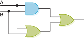
55. Draw a circuit diagram corresponding to the following Boolean expression: (A + B)(B + C)
56. Draw a circuit diagram corresponding to the following Boolean expression: (AB + C)D
57. Draw a circuit diagram corresponding to the following Boolean expression: A’B + (B + C)’
58. Draw a circuit diagram corresponding to the following Boolean expression: (AB)’ + (CD)’
59. Show the behavior of the following circuit with a truth table:
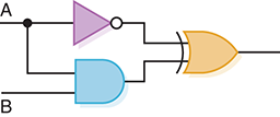
60. Show the behavior of the following circuit with a truth table:
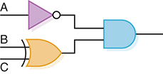
61. Show the behavior of the following circuit with a truth table:
62. Show the behavior of the following circuit with a truth table:
63. What is circuit equivalence?
64. Name six properties of Boolean algebra and explain what each means.
65. Differentiate between a half adder and a full adder.
66. What is the Boolean expression for a full adder?
67. What is a multiplexer?
68.
Circuits used for memory are what type of circuits?
How many digits does an S-R latch store?
The design for an S-R latch shown in Figure 4.12 guarantees what about the outputs X and Y?
69. What is an integrated circuit or chip?
70. Define the abbreviations SSI, MSI, LSI, and VLSI.
71. In the chip shown in Figure 4.13, what are the pins used for?
72. Draw a circuit using two full adders that adds two 2-bit binary values. Show its corresponding truth table.
73. How can the XOR operation be expressed using other operators?
THOUGHT QUESTIONS
Throughout this chapter we have used Boolean expressions, truth tables, and logic diagrams to describe the same behavior. Are the relationships among these notational methods clear to you? Which do you find the most intuitive? Which do you find the least intuitive?
Many situations can be described by the ideas in this chapter—for example, the operation of a single light switch or a light that has two switches. Can you think of other everyday occurrences that can be described by the notational methods presented in this chapter?
How do the two sets of codes of ethics presented at the end of this chapter differ? How are they similar?
Have you ever sent email to someone, only to regret it immediately? Do you find that you would say something in email that you would never say in person? Consider the following premise: “Email has lowered the civility of personal discourse.” Do you agree or disagree?
If a person sends email from a school computer or a business computer, should that message be considered private? Does the institution or person that owns the computer from which email is sent have a right to inspect the message?