
When looking at the DC side of the system, you will always refer to the
156 percent rule mentioned above. On the AC side, overcurrent protection
requires a multiplier of 125 percent. This must be addressed in the PV system
design and installation for safety reasons.
Use the NEC code to establish the proper conductor and conduit sizing that
meets the minimum legal standards. Think beyond the NEC requirements when
designing at high temperatures. Look at the options when selecting panels, con-
duit, and other BOS components. The equipment operates at higher tempera-
tures than it is usually designed for—in almost every environment.
For example, to improve performance, you will want to increase the con-
ductor and conduit size. This reduces resistance from the wire. It also eases the
conductor pulling and reduces temperatures in the conduit. The larger conduit
allows conductors to radiate more heat. This, in turn, keeps the conductors cooler.
Voltage Drop for Circuits
Voltage drops cause and complicate PV system performance issues. Drops in
voltage are not considered safety issues; therefore, the NEC does not address them
at length. It is often recommended by default in the PV industry that voltage
drops be among 3 percent to 5 percent of the overall operating voltage. Five per-
cent is thought to be the greatest recommended drop in voltage for circuits for the
entire PV system.
Think of a voltage drop as an energy and money loss. This loss continues for
the life of the system.
During the design phase, use NEC guidelines to create a safe system.
After you design for and meet NEC guidelines, cut those voltage drops to
1 percent. This ensures greater performance. It costs more up
front, but it will pay for itself numerous times over the life of
the PV system.
It is up to the PV designer to determine the best perfor-
mance level. When designing a PV system under 100V, voltage
drops are critically important factors. Thinking about voltage
drops during the design phase will influence which wires and
conductors you choose for the PV system. Taking voltage
drops into account also may affect termination of those wires.
In addition to wire size, wire length from component to component influences
the voltage drops for circuits.
Determining Voltage Drop. Ohm’s Law (V = I × R) is the equation for deter-
mining voltage drops.
It is represented in the following forms:
V = IR or I =V/R or R=V/I
V = voltage in volts (V)
NOTE
No matter what the size of the wire,
drops in voltage occur as current and
temperature increase or as the length of
the wire increases.
162 ADVANCED PHOTOVOLTAIC INSTALLATIONS
I = current in amps (A)
R = resistance in ohms (Ù)
Voltage drop can also be calculated with an equation to find the voltage drop
index (VDI):
VDI =
amps × wire length in feet
______________________
% voltage drop × voltage
Where amps is the maximum number of amps running through the circuit;
feet is the length of the wire run in feet; percent voltage drop is the percentage of
voltage drop desired; and voltage is the nominal system voltage.
In order to maintain an overall voltage from within 3 to 5 percent, individual
circuits have to have low drops in voltage. Voltage drops can add up quickly if
wire size is not properly taken into account. It is recommended that the wire used
between the charge controller and the combiner box be 6AWG, at a minimum.
The system voltage preference for most applications is 48 volts, because the
voltage drops decrease by 25 percent moving from a 24V system to a 48V system.
There are other voltage drops that are inescapable, yet very controllable.
These voltage drops can cause a 0.5 percent to 4 percent increase in a 24V PV
system size or loss depending on how you look at it.
These components include:
Fuses
Circuit breakers
Switches
Charge controllers
The quality of the terminations for all of the above
Remember to use only wires marked “sunlight resistant” in exposed loca-
tions, and even so, to keep them out of the sun if you are looking for performance.
Be sure to use the appropriate ampacity for the conductors. As wire sizes increase,
they reduce the resistance and voltage drops. Make sure that the terminals and
conduit are designed to accept the increase in wire size.
When selecting combiners, disconnects, etc., make sure that the box that houses
all the circuits and fuses is large enough for the conductor. Also, ensure that the box
has sufficient access for your fingers to terminate them properly. NEC Article 314
has specific information on box size based on the wire size used during installation;
you may want to find equipment that is more generous than the minimum.
Sizing Conductors Based on Power and Required OCPD Ratings
When the wire sizing for the space between the junction box to the source-circuit
combiner box is complete, the next step is to select fuse sizes for the source cir-
cuits. Fuse and circuit breakers safeguard PV modules and the wires from reverse
current flow. Too much reverse current flow can damage the interconnects,
CHAPTER 7 PV Technology—Cells, Panels, Arrays, Balance of System, and Inverters 163

wiring, and PV modules. Fuses and circuit breakers also are known as overcurrent
protection devices (OCPD).
The OCPD size needed for the modules is the easiest to determine. The label
on the back of the PV module lists information about the module from UL testing
and requirements. One piece of that information is the maximum series fuse, the
biggest size fuse or breaker permissible with the module.
For the wire size and in all other DC power areas, you must calculate the
values needed. The NEC requires that wire sizes be 156 percent of the calculated
short-circuit current found from the PV module’s STC rating. This NEC require-
ment is for overcurrent protection.
Fuses are normally cartridge-type fuses that use a pullout fuse holder. Fuse
holders have added safety precautions for fingers. The ends of fuses have the
greatest voltage concentration. Touching the ends of fuses could cause electrical
shock or electrical burns.
After you choose the fuse sizes for the source circuits, the next consideration
is charge controller or inverter wire sizing. The wiring size for the DC side is based
on the short-circuit current rated at 156 percent. When sizing wiring for the
source circuit, take a few things into consideration, including:
Temperature
Conduit fill
Limitations in terminal temperature
Voltage drop
Performance
The rest of the PV system wiring (AC) must be sized at
the rating of 125 percent of the continuous current pulled by
the load.
When determining wiring for the circuit that connects
the distribution panel board to the loads, take into account
the following:
NOTE
Fuses for combiners are available in
various sizes from 1 A to 30 A.
NOTE
When designing cables for batteries,
remember that the current calculations
will require much larger cables and
fuses or breakers.
NOTE
DC circuits require DC-rated
components. Do not substitute AC
components for DC uses. [NEC 690.9(d)]
Load current
Temperature
Conduit fill
Voltage drop—likely in PV systems with less than 48V
Grounding
Grounding means making a connection to ground. It is very
important in PV installations. Grounding is designed so that
no current flows between bare metal PV system components
and the ground. Unwanted current can cause equipment
damage, personal injury, or death. Proper grounding and
164 ADVANCED PHOTOVOLTAIC INSTALLATIONS
overcurrent protection limit damage that ground faults cause. Grounding helps to
prevent instances of electrical shock and fire hazards.
Grounding PV system and PV components is crucial to the continued life of
the PV system. It is also vital for the safety of the customers. PV arrays should be
grounded with approved lugs or equipment grounding screws. Secure every array
and mounting rail with an approved grounding method. Grounding materials
should be stainless steel or bimetallic; that way the grounding materials bond the
array frames to roof-mounted rails electrically. The arrays and rails are then
attached to the grounding wire. There are four types of grounding used in PV
system installation:
Ground-fault protection
Equipment grounding
Systems grounding
Equipment and systems ground continuity
Ground-fault protection (GFP) devices are located within inverters and
charge controllers. They are intended to interrupt the conductor that is not
grounded. They also separate the connection between the grounded conductor
and grounding device for the PV system. NEC Article 690.5 requires that ground
fault protection be added to all grounded PV arrays to diminish fire hazards.
There are two exceptions:
For ground or pole-mounted arrays with fewer than two strings in parallel
For PV arrays installed on non-habitable buildings, such as parking
structures or storage sheds
Some PV systems are equipped with batteries as backup power sources. Bat-
teries convert the chemical energy directly into electrical energy by means of an
electrochemical reaction. PV systems with battery backups are encouraged to
have charge controllers installed to keep from overcharging or undercharging the
batteries, which will kill them prematurely. By avoiding the use of a charge con-
troller with MPPT, the batteries can also be kept for week or months in an under-
voltage state, not just at an overvoltage one. In PV systems with charge controllers,
the GFP mechanism is attached to the charge controller input because the PV
system’s output connects directly to the charge controller.
Equipment grounding is required by NEC Article 690.43. It requires that “all
exposed non-current-carrying metal parts of components be grounded in accor-
dance with NEC 250.134 or 250.136(A), regardless of the system voltage.” In lay
terms, this means that all metal equipment must be grounded with conductors.
This should be done regardless of whether the PV array conductors are grounded.
Equipment grounding conductors should be a bare wire or green wire [NEC
250.119]. Equipment grounding conductors need to handle the highest current
that could flow through the circuit [NEC 250.122].
CHAPTER 7 PV Technology—Cells, Panels, Arrays, Balance of System, and Inverters 165
System grounding is required for both AC and DC
systems. Their requirements are comparable. NEC Article
690.47 is the principle for grounding electrode systems. NEC
Article 690.47 also establishes the size of the grounding
conductor.
The most critical point to remember in installing a PV
system is that it never stops working. Even when the system is
offline, the solar panels are still generating energy. One of the biggest hazards for
workers is thinking that the system is grounded when system maintenance is per-
formed, when it is not!
In order to stop ungrounding from occurring, PV equipment and PV sys-
tems need continuous grounding mechanisms in place. Fail-safes are very impor-
tant. Two simple fail-safes are to install jumpers for PV equipment and output
conductors during inverter removal. Two provisions of the NEC, Article 690.48
and 690.49, address the conditions for jumpers.
Batteries and Battery Wiring
Batteries can be the most dangerous component in a PV system. Batteries can
store thousands of amps. A short in the battery or damage to the terminal can
cause arcs, shocks, fires, and explosions.
TECH TIPS
There are grounding electrode
conductors for the AC and DC side of
the system. Bond them together.
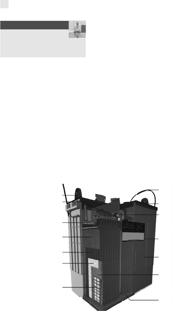
FIGURE 7-2 This figure shows the inner workings of a lead-acid battery.
Courtesy of Surrette
Negative terminal
Handle
Heat seal welded blue cover
Interconnected
tombstone weld
Date code
High-density structural
foam polyethylene
Minimal mud rest
Cast-on strap
and post
Polyethylene envelope
Negative plate
Positive plate
Double-wrap
glass matting
Positive grid
Maximum liquid
reserve
24736_CH07_FIG02
166 ADVANCED PHOTOVOLTAIC INSTALLATIONS
..................Content has been hidden....................
You can't read the all page of ebook, please click here login for view all page.