your customer and make your job easier and your work of higher quality. This
will become obvious when you come back years later for service.
According to NEC Article 690.53, the installer should ensure that permanent
labels for the DC PV power source have the following information at the photo-
voltaic disconnecting means:
Rated maximum power point current (Imp)
Rated maximum power point voltage (Vmp)
Maximum system voltage (Voc)
Short-circuit current (Isc)
Maximum rated output current of the charge controller (if installed)
If you write labels by hand, use indelible ink and a professional, steady hand.
Wiring
Module Interconnections
There are different types of wires, conductors, and
cables. Electrical wires are made with different con-
ductor materials and have different insulating
materials. Electrical wire voltage ratings also vary. It
is important to select the correct wire for each
application (see Table 8-1, 8-2, and 8-3).
Aluminum and copper are the most common
conductors used in residential and commercial
applications. Copper is more conductive; that is, it
carries more current than aluminum.
The NEC does not allow aluminum wiring for
residential PV use. It is not as strong as copper
wiring. It is also easily damaged during installation.
It is employed frequently in commercial wiring,
such as larger gauges used by utilities, because it is
less expensive than copper.
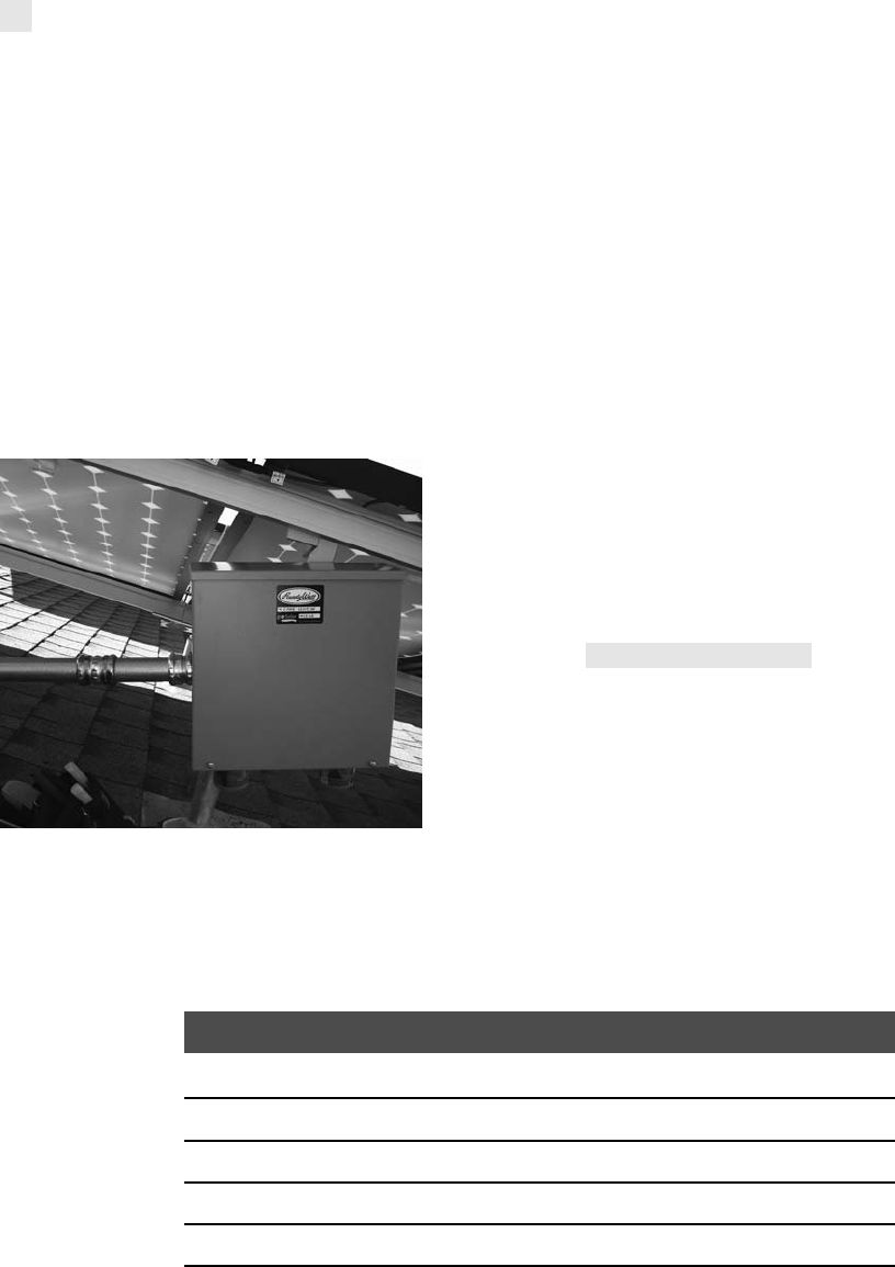
TABLE 8-1 COPPER WIRE AMPACITY
Ampacity
Conductor Size (AWG) 60°C 75°C
30 – 0.5
28 – 0.8
26 – 1
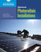
It is important to protect outside wiring from the sun,
rain, animals, and people.
Courtesy of PerfectPower, Inc.
182 ADVANCED PHOTOVOLTAIC INSTALLATIONS
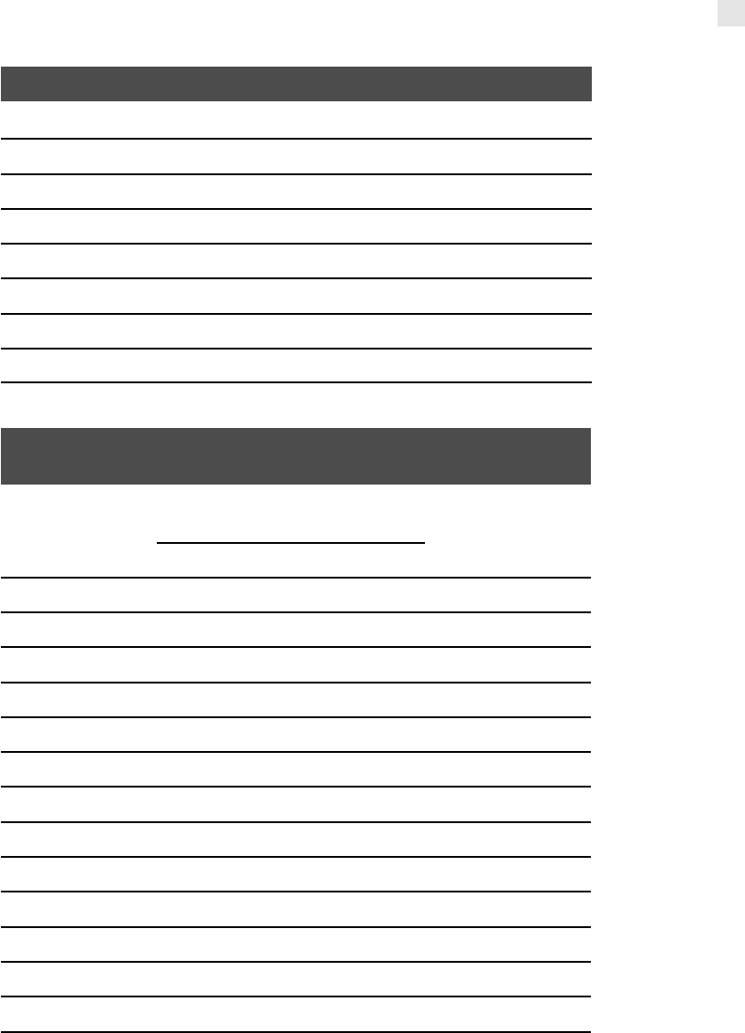
TABLE 8-1 COPPER WIRE AMPACITY, (CONTINUED)
Ampacity
Conductor Size (AWG) 60°C 75°C
24 2 2
22 3 3
20 5 5
18 7 7
16 10 10
Courtesy of National Fire Protection Association (NFPA)
TABLE 8-2 AMBIENT TEMPERATURE CORRECTION FACTORS BASED
ON 30 DEGREES CELSIUS (86 DEGREES FAHRENHEIT)
Ambient
Temperature (°C)
Temperature Rating
of Conductor
Ambient
Temperature (°F)60°C 75°C 90°C
10 or less 1.29 1.20 1.15 50 or less
11–15 1.22 1.15 1.12 51–59
16–20 1.15 1.11 1.08 60–68
21–25 1.08 1.05 1.04 69–77
26–30 1.00 1.00 1.00 78–86
31–35 0.91 0.94 0.96 87–95
36–40 0.82 0.88 0.91 96–104
41–45 0.71 0.82 0.87 105–113
46–50 0.58 0.75 0.82 114–122
51–55 0.41 0.67 0.76 123–131
56–60 – 0.58 0.71 132–140
61–65 – 0.47 0.65 141–149
66–70 – 0.33 0.58 150–158
(continues)
CHAPTER 8 Connecting the Sun to the Home and the Utility 183
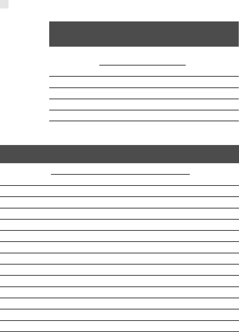
TABLE 8-2 AMBIENT TEMPERATURE CORRECTION FACTORS BASED
ON 30 DEGREES CELSIUS (86 DEGREES FAHRENHEIT),
(CONTINUED)
Ambient
Temperature (°C)
Temperature Rating
of Conductor
Ambient
Temperature (°F)60°C 75°C 90°C
71–75 – – 0.50 159–167
76–80 – – 0.41 168–176
81–85 – – 0.29 177–185
Courtesy of NFPA
TABLE 8-3 AMBIENT TEMPERATURE CORRECTION FACTORS BASED ON 40 DEGREES
CELSIUS (104 DEGREES FAHRENHEIT)*
Ambient
Temperature (°C)
Temperature Rating of Conductor
Ambient
Temperature (°F)60°C 75°C 90°C 150°C 200°C 250°C
10 or less 1.58 1.36 1.26 1.13 1.09 1.07 50 or less
11–15 1.50 1.31 1.22 1.11 1.08 1.06 51–59
16–20 1.41 1.25 1.18 1.09 1.06 1.05 60–68
21–25 1.32 1.20 1.14 1.07 1.05 1.04 69–77
26–30 1.22 1.13 1.10 1.04 1.03 1.02 78–86
31–35 1.12 1.07 1.05 1.02 1.02 1.01 87–95
36–40 1.00 1.00 1.00 1.00 1.00 1.00 96–104
41–45 0.87 0.93 0.95 0.98 0.98 0.99 105–113
46–50 0.71 0.85 0.89 .095 0.97 0.98 114–122
51–55 0.50 0.76 0.84 0.93 0.95 0.96 123–131
56–60 – 0.65 0.77 0.90 0.94 0.95 132–140
61–65 – 0.53 0.71 0.88 0.92 0.94 141–149
66–70 – 0.38 0.63 0.85 0.90 0.93 150–158
184 ADVANCED PHOTOVOLTAIC INSTALLATIONS

TABLE 8-3 AMBIENT TEMPERATURE CORRECTION FACTORS BASED ON 40 DEGREES
CELSIUS (104 DEGREES FAHRENHEIT)*, (CONTINUED)
Ambient
Temperature (°C)
Temperature Rating of Conductor
Ambient
Temperature (°F)60°C 75°C 90°C 150°C 200°C 250°C
71–75 – – 0.55 0.83 0.88 0.91 159–167
76–80 – – 0.45 0.80 0.87 0.90 168–176
81–90 – – – 0.74 0.83 0.87 177–194
91–100 – – – 0.67 0.79 0.85 195–212
101–110 – – – 0.60 0.75 0.82 213–230
111–120 – – – 0.52 0.71 0.79 231–248
121–130 – – – 0.43 0.66 0.76 249–266
131–140 – – – 0.30 0.61 0.72 267–284
141–160 – – – – 0.50 0.65 285–320
161–180 – – – – 0.35 0.58 321–356
181–200 – – – – – 0.49 357–392
201–225 – – – – – 0.35 393–437
*For ambient temperatures other than 40ºC (104ºF), multiply the allowable ampacities specified in the ampacity
tables by the appropriate correction factor shown above.
Courtesy of NFPA
Consider the type of insulation used. The insulation protects the wire from damage and stops the
current from transferring from the wire to surrounding materials and shorting out. The NEC provides
codes on what kind of conductors may be used for different applications:
Thermoplastic high heat-resistant nylon-coated (THHN) is rated for use in dry and damp
indoor areas.
Thermoplastic heat and water-resistant (THW), thermoplastic heat and water-resistant nylon-
coated (THWN), and thermoplastic water-resistant (TW) are rated for use indoors and in
conduit for wet and outdoor applications.
Underground feeder (UF) and underground service entrance (USE) wire are rated for
underground installation and damp areas.
Type UF cable is not usually accessible. It also is rated for maximum 60 degree Celsius tempera-
tures. Most PV application should use 90 degree Celsius for long-term serviceability and performance
CHAPTER 8 Connecting the Sun to the Home and the Utility 185
Table 8-4. PV modules have surface and surrounding temperatures well above
60 degrees Celsius. The USE-2 cable is recommended for PV module intercon-
nections. It is rated for 90 degree Celsius, 194 degree Fahrenheit temperatures. It
also is resistant to sunlight and is rated for damp conditions. USE-2 cannot be
used as conduit inside a building unless it also has a flame-retardant rating, such
as rubber-insulated high heat-insulated (RHH) wire or rubber-insulated high
water resistant-insulated (RHW) wire. If possible, we recommend keeping all
conductors, except bare ground conductors, out of the sun and in metal
conduit.
TABLE 8-4 TEMPERATURE RATINGS OF CONDUCTORS
AWG
or
kcmil
Temperature Rating of Conductor [See Table 310.104(A)]
AWG
or
kcmil
60°C
(140°F)
75°C
(167°F) 90°C (194°F)
60°C
(140°F)
75°C
(167°F)
90°C
(194°F)
Types
TW, UF
Types
RHW,
THHW,
THW,
THWN,
XHHW,
USE, ZW
Types TBS,
SA, SIS, FEP,
FEPB, MI, RHH,
RHW-2, THHN,
THHW, THW-2,
THWN-2,
USE-2, XHH,
XHHW,
XHHW-2,
ZW-2
Types
TW, UF
Types
RHW,
THHW,
THW,
THWN,
XHHW,
USE
Types TBS, SA,
SIS, THHN,
THHW, THW-2,
THWN-2, RHH,
RHW-2, USE-2,
XHH, XHHW,
XHHW-2, ZW-2
COPPER ALUMINUM OR COPPER-CLAD
ALUMINUM
18
16
14**
12**
10**
8
–
–
15
20
30
40
–
–
20
25
35
50
14
18
25
30
40
55
–
–
–
15
25
35
–
–
–
20
30
40
–
–
–
25
35
45
–
–
–
12**
10**
8
6
4
3
2
1
55
70
85
95
110
65
85
100
115
130
75
95
115
130
145
40
55
65
75
85
50
65
75
90
100
55
75
85
100
115
6
4
3
2
1
186 ADVANCED PHOTOVOLTAIC INSTALLATIONS
..................Content has been hidden....................
You can't read the all page of ebook, please click here login for view all page.