Once the prep work is complete, it is time to plan the layout of the PV arrays.
It is helpful to have an exact plan of the roof, including:
Dimensions of the roof surface, height, angle, and position of the existing
roof structure
Spacing and position of the rafters
Shading analysis to locate trees and other structures (i.e., chimneys, adjacent
buildings, etc.) that could shade the arrays
Structural calculations to determine the number of roof hooks and the
screw sizes required
Location for an access panel for maintenance, expansion, or a solar
thermal system
You must also have an electrical wiring diagram with the exact wiring dis-
tances and equipment for the following:
1. Panel, string, and array map of panels, and string wiring to the combiner for
later inspection and testing
2. String wiring
3. Inverter position
4. SES and utility meter
5. PV combiner, pass-through, and junction box
6. Cabling system between the PV panels and the inverter
Step-by-Step System Installation
Installing a PV system is a construction process that involves specific actions that
you must take in a specific order. These are the nine steps, discussed in greater
detail in the following sections:
1. Lay out the arrays.
2. Do any tile or shingle cutting required.
3. Fit and install the panel rails and legs.
4. Ground the array support structure.
5. Mount the panels.
6. Run the cables through the roof.
7. String wire installation inside the building.
8. Install the inverter.
9. Install the service entrance section (SES) connection.
Here are the steps in more detail:
Laying out the arrays. After measuring the estimated electricity consumption,
you need to determine how big a PV array you need to produce that amount of
electricity. The PV industry has many options available for PV arrays.
16 ADVANCED PHOTOVOLTAIC INSTALLATIONS

Cutting tile or shingles. Remove roof tiles or shingles down
to the rafters. Rafters must be visible for you to attach the roof
hooks. Use a shim plate if the roof hook does not clear the
closest roof tile or shingle by five millimeters (5 mm). Use
timber screws that are at least eight millimeters (8 mm)
around and 80 millimeters (80 mm) long. The screws need to
be longer if insulation is located over the rafters. Once roof
hooks are in place, the roof tiles or shingles must also go back
into position. However, you will need to cut them first. The
grooves on certain types of roofing conflict with the roof
hooks. Smooth the grooves in order to fit against the roof
hooks. You may need to sand down several roof tiles or shin-
gles to put the roof back together.
Running cables through the roof. Protect the string cables.
Clip them to the rails with metal clips so they will not snag on
anything, blow in the wind, or be disturbed by rain, snow, or
ice. Plastic ties will not last more than about five years in most
locations. National Electrical Code (210.20(b), 240.100(2)(c))
NOTE
Always use chalk to mark out the
position of the arrays.
NOTE
Roof hooks should not change the
position of the roof tiles or shingles. If
they do, this could lead to roof leaks.
NOTE
Use waterproof spacers made out of
Neoprene between the angle brackets
and the module frame.
CODE
NEC 2011, 210.20
210.20 Overcurrent Protection. Branch-circuit conductors and equipment shall be protected
by overcurrent protective devices that have a rating or setting that complies with 210.20(A)
through (D).
(A) Continuous and Noncontinuous Loads. Where a branch circuit supplies continuous loads
or any combination of continuous and noncontinuous loads, the rating of the overcurrent device
shall not be less than the noncontinuous load plus 125 percent of the continuous load. Excep-
tion: Where the assembly, including the overcurrent devices protecting the branch circuit(s), is
listed for operation at 100 percent of its rating, the ampere rating of the overcurrent device shall
be permitted to be not less than the sum of the continuous load plus the noncontinuous load.
(B) Conductor Protection. Conductors shall be protected in accordance with 240.4. Flexible cords and
fixture wires shall be protected in accordance with 240.5.
(C) Equipment. The rating or setting of the overcurrent protective device shall not exceed that
specified in the applicable articles referenced in Table 240.3 for equipment.
(D) Outlet Devices. The rating or setting shall not exceed that specified in 210.21 for outlet devices.
Reprinted with permission from NFPA 70
®
, National Electrical Code
®
, Copyright
©
2010, National Fire
Protection Association, Quincy, MA.
CHAPTER 1 Introduction to Advanced Photovoltaic System Installation 17

requires that you protect the conductors. They connect the arrays on the roof to
the rest of the PV system.
The best housing for string cables will vary depending upon conditions. House
string cables in thermal-insulated, waterproof, and UV-resistant pipes. Running
string cables through protective tubes helps ensure long service life and bolster
system safety. Consider running cables through protective conduit wherever animals
can get to them, or where cables may be exposed to ice, freezing, or direct sunlight.
Taking the extra steps adds to service life and system safety while reducing
long-term maintenance. Too many wires or wires too big for the conduit will
result in overheating. Select the correct pipe size. It may be easier and it may
reduce conductor temperatures to use conduit one size larger than is absolutely
needed. This is particularly useful in moderate to hot climates for better summer
performance and better protects conductor insulation.
Installing the string wiring inside the building. All con-
ductors must be in metal conduit within the building. The
string wiring should run the shortest practical distance to the
DC disconnect switch, or the array combiner/junction box.
They should be marked, especially if they are routed along the
same path as other wiring in the building. Use the correct
insulator color-coding.
Installing the inverter. Locate inverters to provide easy access for maintenance
and servicing. Inverters should also be installed in a place where faultless opera-
tion is guaranteed. Inverters should be located out of direct sunlight and in a tem-
perature-controlled area. Dry areas are also suitable for inverters.
Remember that installing inverters in a residential or commercial building
can produce additional heat gain to the areas near the inverter. In a cold climate,
this may be a good thing. The additional heat will be welcome in the building. In
a moderate to hot climate, the excess heat will need to be removed or the space
may need additional air conditioning. This in effect reduces the system’s overall
efficiency.
Consider the operational environment when placing inverters in
high-temperature locations. Mounting in an unvented closet or utility room will
raise the temperature of the room and the inverter. Higher temperatures will
shorten the inverter life and affect performance. Never locate an inverter in an
area where it will meet or exceed its designed operational temperature. Be aware
of airflow and venting. Do not install one passively cooled inverter directly under
or over another one. Unless there is sufficient space to dissipate the heat, doing so
NOTE
Protective conduits must be
UV-resistant and rated for external use.
18 ADVANCED PHOTOVOLTAIC INSTALLATIONS
will raise the temperature of the upper unit. This is not good.
When using side-vented inverters, leave enough space so the
heated exhaust will not enter the intake of another inverter.
Manufacturers will advise using higher operating ranges
and inverter loading practices to meet warranty requirements.
You should load the inverter at less than its maximum
capacity and run it at a temperature below the maximum as
well. Doing so will provide a longer inverter life and poten-
tially higher inverter performance.
Installing the service entrance section (SES) connection.
The service entrance is the gateway between the customer’s
property and the utility. It has special require-
ments that allow for connection between the
grid and the PV system. The DC power gen-
erated from the arrays and turned into AC
power—often termed inverter output—needs
some place to go. Inverter output will usually
be used on-site first. With traditional utility
setups, buildings have utility meters in
place already.
Once you have installed the supply
meter, switch on the mains connection. From
there the inverter begins operation. The
readings from the inverter determine
whether the PV system is functioning
as intended.
NOTE
System monitoring. A data line or
wireless link can transfer system data
to a computer directly or through an
Internet based system. This is extremely
important for monitoring the system,
tracking it, and knowing how well it’s
working. A PV system without remote
monitoring is a subprime system. It is
like driving a car without gauges or a
speedometer, a very unwise practice.
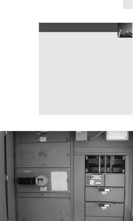
Commercial service entrance at a PerfectPower installation site.
Courtesy of PerfectPower, Inc.
CHAPTER 1
Introduction to Advanced Photovoltaic System Installation 19

Alternating current (AC)
Array
Authority having jurisdiction (AHJ)
Balance-of-system (BOS)
Battery
Combiner box
Direct current (DC)
Energy audit
Grid
Grid-connected (or grid-tied) system
Inverter
Meter
Orientation
PV arrays
String
Chapter 1 Summary
This chapter provides a general overview of advanced PV system installation. Basic principles
and concepts create a foundation for understanding the design and installation of PV sys-
tems. The installation checklist presents a systematic review of the necessary components
within a PV system. Installation notes aid the step-by-step instructions for installing PV
systems.
Key ConCeptS and termS
Chapter 1 aSSeSSment
Introduction to Advanced Photovoltaic System Installation
1. Coated or painted steel should be used only in dry climates such as deserts.
A. True
B. False
2. When installing roof hooks to a building’s rafters, what is the minimum size of the timber
screw needed?
A. 25 mm
B. 2 mm
C. 8 mm
D. 13 mm
3. A roof must be sealed many times during PV array installation. Which of the following are
approved roof sealants? (Select two.)
A. Tar
B. Bitumen roofing felt
C. Plastic roof sheeting
D. Cardboard
20
ADVANCED PHOTOVOLTAIC INSTALLATIONS
..................Content has been hidden....................
You can't read the all page of ebook, please click here login for view all page.