
5.2 The Stored-Program Concept
A major defining point in the history of computing was the realization in 1944–1945 that data and instructions to manipulate the data were logically the same and could be stored in the same place. The computer design built upon this principle, which became known as the von Neumann architecture, is still the basis for computers today. Although the name honors John von Neumann, a brilliant mathematician who worked on the construction of the atomic bomb, the idea probably originated with J. Presper Eckert and John Mauchly, two other early pioneers who worked on the ENIAC at the Moore School at the University of Pennsylvania during the same time period.
von Neumann Architecture
Another major characteristic of the von Neumann architecture is that the units that process information are separate from the units that store information. This characteristic leads to the following five components of the von Neumann architecture, shown in FIGURE 5.1 :
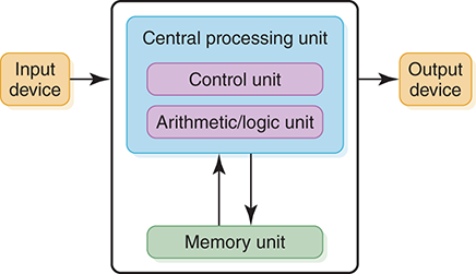
FIGURE 5.1 The von Neumann architecture
The memory unit, which holds both data and instructions
The arithmetic/logic unit, which is capable of performing arithmetic and logic operations on data
The input unit, which moves data from the outside world into the computer
The output unit, which moves results from inside the computer to the outside world
The control unit, which serves as the stage manager to ensure that all the other components act in concert
Memory
Recall from the discussion of number systems that each storage unit, called a bit, is capable of holding a 1 or a 0; these bits are grouped together into bytes (8 bits), and these bytes are in turn grouped together into words. Memory is a collection of cells, each with a unique physical address. We use the generic word cell here rather than byte or word, because the number of bits in each addressable location, called the memory’s addressability, varies from one machine to another. Today, most computers are byte addressable.
The ad in the previous section describes a memory of 4 × 230 bytes. This means that each of the 4 GB is uniquely addressable. Therefore, the addressability of the machine is 8 bits. The cells in memory are numbered consecutively beginning with 0. For example, if the addressability is 8, and there are 256 cells of memory, the cells would be addressed as follows:
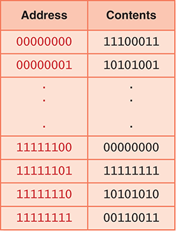
What are the contents of address 11111110? The bit pattern stored at that location is 10101010. What does it mean? We can’t answer that question in the abstract. Does location 11111110 contain an instruction? An integer with a sign? A two’s complement value? Part of an image? Without knowing what the contents represent, we cannot determine what it means: It is just a bit pattern. We must apply an interpretation on any bit pattern to determine the information it represents.
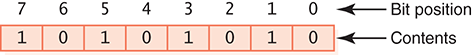
When referring to the bits in a byte or word, the bits are numbered from right to left beginning with zero. The bits in address 11111110 are numbered as follows:
Arithmetic/Logic Unit
The arithmetic/logic unit (ALU) is capable of performing basic arithmetic operations such as adding, subtracting, multiplying, and dividing two numbers. This unit is also capable of performing logical operations such as AND, OR, and NOT. The ALU operates on words, a natural unit of data associated with a particular computer design. Historically, the word length of a computer has been the number of bits processed at once by the ALU. However, the current Intel line of processors has blurred this definition by defining the word length to be 16 bits. The processor can work on words (16 bits), double words (32 bits), and quadwords (64 bits). In the rest of this discussion, we continue to use word in its historical sense.
Most modern ALUs have a small number of special storage units called registers. These registers contain one word and are used to store information that is needed again immediately. For example, in the calculation of
One * (Two + Three)
Two is first added to Three and the result is then multiplied by One. Rather than storing the result of adding Two and Three in memory and then retrieving it to multiply it by One, the result is left in a register and the contents of the register are multiplied by One. Access to registers is much faster than access to memory locations.
Input/Output Units
All of the computing power in the world wouldn’t be useful if we couldn’t input values into the calculations from outside or report to the outside the results of those calculations. Input and output units are the channels through which the computer communicates with the outside world.
An input unit is a device through which data and programs from the outside world are entered into the computer. The first input units interpreted holes punched on paper tape or cards. Modern-day input devices include the keyboard, the mouse, and the scanning devices used at supermarkets.
An output unit is a device through which results stored in the computer memory are made available to the outside world. The most common output devices are printers and displays.
Control Unit
The control unit is the organizing force in the computer, for it is in charge of the fetch–execute cycle, discussed in the next section. There are two special registers in the control unit. The instruction register (IR) contains the instruction that is being executed, and the program counter (PC) contains the address of the next instruction to be executed. Because the ALU and the control unit work so closely together, they are often thought of as one unit called the central processing unit, or CPU.
FIGURE 5.2 shows a simplified view of the flow of information through the parts of a von Neumann machine. The parts are connected to one another by a collection of wires called a bus, through which data travels in the computer. Each bus carries three kinds of information: address, data, and control. An address is used to select the memory location or device to which data will go or from which it will be taken. Data then flows over the bus between the CPU, memory, and I/O devices. The control information is used to manage the flow of addresses and data. For example, a control signal will typically be used to determine the direction in which the data is flowing, either to or from the CPU. The bus width is the number of bits that it can transfer simultaneously. The wider the bus, the more address or data bits it can move at once.

FIGURE 5.2 Data flow through a von Neumann machine
Because memory accesses are very time consuming relative to the speed of the processor, many architectures provide cache memory. Cache memory is a small amount of fast-access memory into which copies of frequently used data are stored. Before a main memory access is made, the CPU checks whether the data is stored in the cache memory. Pipelining is another technique used to speed up the fetch–execute cycle. This technique splits an instruction into smaller steps that can be overlapped.
In a personal computer, the components in a von Neumann machine reside physically in a printed circuit board called the motherboard. The motherboard also has connections for attaching other devices to the bus, such as a mouse, a keyboard, or additional storage devices. (See the section on secondary storage devices later in this chapter.)
So just what does it mean to say that a machine is an n-bit processor? The variable n usually refers to the number of bits in the CPU general registers: Two n-bit numbers can be added with a single instruction. It also can refer to the width of the address bus, which is the size of the addressable memory—but not always. In addition, n can refer to the width of the data bus—but not always.
The Fetch–Execute Cycle
Before looking at how a computer does what it does, let’s look at what it can do. The definition of a computer outlines its capabilities: A computer is a device that can store, retrieve, and process data. Therefore, all of the instructions that we give to the computer relate to storing, retrieving, and processing data. In Chapters 6 and 9, we look at various languages that we can use to give instructions to the computer. For our examples here, we use simple English-like instructions.
Recall the underlying principle of the von Neumann machine: Data and instructions are stored in memory and treated alike. This means that instructions and data are both addressable. Instructions are stored in contiguous memory locations; data to be manipulated are stored together in a different part of memory. To start the fetch–execute cycle, the address of the first instruction is loaded into the program counter.
The processing cycle includes four steps:
Fetch the next instruction.
Decode the instruction.
Get data if needed.
Execute the instruction.
Let’s look at each of these steps in more detail. The process starts with the address in memory of the first instruction being stored in the program counter.
Fetch the Next Instruction
The program counter (PC) contains the address of the next instruction to be executed, so the control unit goes to the address in memory specified in the PC, makes a copy of the contents, and places the copy in the instruction register. At this point the IR contains the instruction to be executed. Before going on to the next step in the cycle, the PC must be updated to hold the address of the next instruction to be executed when the current instruction has been completed. Because the instructions are stored contiguously in memory, adding the number of bytes in the current instruction to the program counter should put the address of the next instruction into the PC. Thus the control unit increments the PC. It is possible that the PC may be changed later by the instruction being executed.
In the case of an instruction that must get additional data from memory, the ALU sends an address to the memory bus, and the memory responds by returning the value at that location. In some computers, data retrieved from memory may immediately participate in an arithmetic or logical operation. Other computers simply save the data returned by the memory into a register for processing by a subsequent instruction. At the end of execution, any result from the instruction may be saved either in registers or in memory.
Decode the Instruction
To execute the instruction in the instruction register, the control unit has to determine what instruction it is. It might be an instruction to access data from an input device, to send data to an output device, or to perform some operation on a data value. At this phase, the instruction is decoded into control signals. That is, the logic of the circuitry in the CPU determines which operation is to be executed. This step shows why a computer can execute only instructions that are expressed in its own machine language. The instructions themselves are literally built into the circuits.
Get Data If Needed
The instruction to be executed may potentially require additional memory accesses to complete its task. For example, if the instruction says to add the contents of a memory location to a register, the control unit must get the contents of the memory location.
Execute the Instruction
Once an instruction has been decoded and any operands (data) fetched, the control unit is ready to execute the instruction. Execution involves sending signals to the arithmetic/logic unit to carry out the processing. In the case of adding a number to a register, the operand is sent to the ALU and added to the contents of the register.
When the execution is complete, the cycle begins again. If the last instruction was to add a value to the contents of a register, the next instruction probably says to store the results into a place in memory. However, the next instruction might be a control instruction—that is, an instruction that asks a question about the result of the last instruction and perhaps changes the contents of the program counter.
FIGURE 5.3 summarizes the fetch–execute cycle.
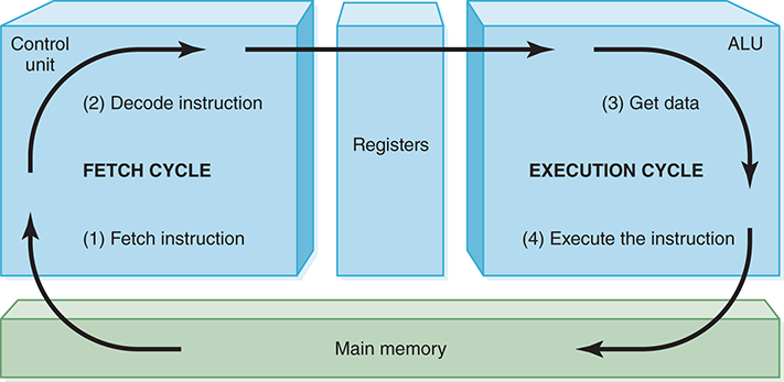
FIGURE 5.3 The fetch–execute cycle
Hardware has changed dramatically in the last half-century, yet the von Neumann machine remains the basis of most computers today. As Alan Perlis, a well-known computer scientist, said in 1981, “Some-times I think the only universal in the computing field is the fetch–execute cycle.”3 This statement is still true today, more than three decades later.
RAM and ROM
As mentioned, RAM stands for random-access memory. RAM is memory in which each cell (usually a byte) can be directly accessed. Inherent in the idea of being able to access each location is the ability to change the contents of each location. That is, storing something else into that place can change the bit pattern in each cell.
In addition to RAM, most computers contain a second kind of memory, called ROM. ROM stands for read-only memory. The contents in locations in ROM cannot be changed. Their contents are permanent and cannot be altered by a stored operation. Placing the bit pattern in ROM is called burning. The bit pattern is burned either at the time the ROM is manufactured or at the time the computer parts are assembled.
RAM and ROM are differentiated by a very basic property: RAM is volatile; ROM is not. This means that RAM does not retain its bit configuration when the power is turned off, but ROM does. The bit patterns within ROM are permanent. Because ROM is stable and cannot be changed, it is used to store the instructions that the computer needs to start itself. Frequently used software is also stored in ROM so that the system does not have to read the software each time the machine is turned on. Main memory usually contains some ROM along with the general-purpose RAM.
Secondary Storage Devices
As mentioned earlier, an input device is the means by which data and programs are entered into the computer and stored into memory. An output device is the means by which results are sent back to the user. Because most of main memory is volatile and limited, it is essential that there be other types of storage devices where programs and data can be stored when they are no longer being processed or when the machine is not turned on. These other types of storage devices (other than main memory) are called secondary or auxiliary storage devices. Because data must be read from them and written to them, each secondary storage device is also an input and an output device.
Secondary storage devices can be installed within the computer box at the factory or added later as needed. Because these devices can store large quantities of data, they are also known as mass storage devices. For example, the hard disk drive that comes with the laptop specified in the ad can store 1000 × 230 bytes as opposed to 4 × 230 bytes in main memory.
The next sections describe some secondary storage devices.
Magnetic Tape
Card readers and card punches were among the first input/output devices. Paper tape readers and punches were the next input/output devices. Although paper tapes, like cards, are permanent, they cannot hold much data. The first truly mass auxiliary storage device was the magnetic tape drive. A magnetic tape drive is like a tape recorder and is most often used to back up (make a copy of) the data on a disk in case the disk is later damaged. Tapes come in several varieties, from small streaming-tape cartridges to large reel-to-reel models.
Tape drives have one serious drawback: To access data in the middle of the tape, all the data before the piece you want must be accessed and discarded. Although modern streaming-tape systems have the capability of skipping over segments of tape, the tape must physically move through the read/write heads. Any physical movement of this type is time consuming. See FIGURE 5.4.
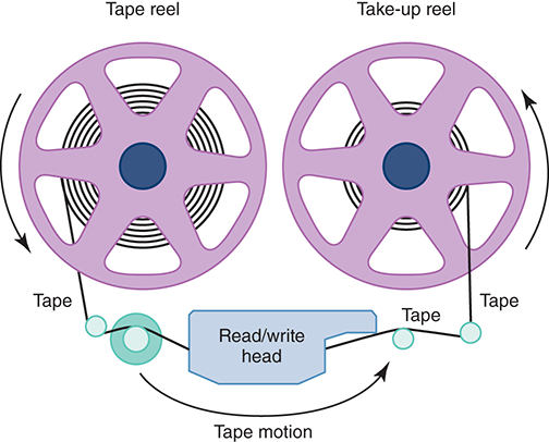
FIGURE 5.4 A magnetic tape
Magnetic Disks
A disk drive is a cross between a compact disc player and a tape recorder. A read/write head (similar to the record/playback head in a tape recorder) travels across a spinning magnetic disk, retrieving or recording data. As on a compact disc, the heads travel directly to the information desired; as on a tape, the information is stored magnetically.
Disks come in several varieties, but all of them consist of a thin disk made out of magnetic material. The surface of each disk is logically organized into tracks and sectors. Tracks are concentric circles around the surface of the disk. Each track is divided into sectors. Each sector holds a block of information as a continuous sequence of bits. See FIGURE 5.5(a). The figure depicts the original layout of data on a disk, in which each track has the same number of sectors, and each sector holds the same number of bits. The blocks of data nearer the center were more densely packed. On modern disks, there are fewer sectors near the middle and more toward the outside. The actual number of tracks per surface and the number of sectors per track vary, but 512 bytes or 1024 bytes is common. (The power of 2 strikes again.) The locations of the tracks and sectors are marked magnetically when a disk is formatted; they are not physically part of the disk.
The read/write head in a disk drive is positioned on an arm that moves from one track to another. See FIGURE 5.5(b). An input/output instruction specifies the track and sector. When the read/write head is over the proper track, it waits until the appropriate sector is beneath the head; it then accesses the block of information in that sector. This process gives rise to four measures of a disk drive’s efficiency: seek time, latency, access time, and transfer rate. Seek time is the time it takes for the read/ write head to get into position over the specified track. Latency is the time it takes for the specified sector to spin to the read/write head. The average latency is one-half the time for a full rotation of the disk. For this reason, latency is also called rotation delay. Access time is the sum of seek time and latency. Transfer rate is the rate at which data is transferred from the disk to memory.

FIGURE 5.5 The organization of a magnetic disk
Now let’s look at some of the varieties of disks. One classification of disk is hard versus floppy. These terms refer to the flexibility of the disk itself. The original floppy disk, introduced in the 1970s, was 8” in diameter and even its case was floppy. By the time of the rise in personal computers in the late 1970s, the floppy disk had been reduced in size to 5 1/4” in diameter. Later, generic “floppy” disks were 3 1/2” in diameter, encased in a hard plastic cover, and capable of storing 1.44 MB of data. Floppy disks are no longer used in modern computers, having been replaced by removable storage such as flash drives (see below). Historically, though, they explain the use of the contrasting term hard disks.
Hard disks actually consist of several disks—this sounds strange, so let’s explain. Let’s call the individual disks platters. Hard disks consist of several platters attached to a spindle that rotates. Each platter has its own read/write head. All of the tracks that line up under one another are called a cylinder (see Figure 5.5(b)). An address in a hard drive consists of the cylinder number, the surface number, and the sector. Hard drives rotate at much higher speeds than floppy drives do, and the read/write heads don’t actually touch the surface of the platters but rather float above them. A typical hard disk drive rotates at 7200 revolutions per minute. Laptop hard disks usually spin at 5400 RPM, conserving battery power. The disks in high-performance servers may run at 15,000 RPM, providing lower latency and a higher transfer rate.
CDs and DVDs
The world of compact discs and their drivers looks like acronym soup. The ad we examined used the acronym DVD+/−RW. In addition, we have to decipher CD-DA, CD-RW, and DVD.
Let’s look for a moment at the acronym CD. CD, of course, stands for compact disc. A CD drive uses a laser to read information that is stored optically on a plastic disk. Rather than having concentric tracks, a CD has one track that spirals from the inside out. As on magnetic disks, this track is broken into sectors. A CD has the data evenly packed over the whole disk, so more information is stored in the track on the outer edges and read in a single revolution. To make the transfer rate consistent throughout the disk, the rotation speed varies depending on the position of the laser beam.
The other letters attached to CD refer to various properties of the disk, such as formatting and whether the information on the disk can be changed. CD-DA is the format used in audio recordings; CD-DA stands for compact disc–digital audio. Certain fields in this format are used for timing information. A sector in a CD-DA contains 1/75 of a second of music.
CD-ROM is the same as CD-DA, but the disk is formatted differently. Data is stored in the sectors reserved for timing information in CD-DA. ROM stands for read-only memory. As we said earlier, read-only memory means that the data is permanent and cannot be changed. A sector on a CD-ROM contains 2 KB of data. CD-ROM capacity is in the neighborhood of 600 MB.
CD-R stands for recordable, allowing data to be written after it is manufactured. The contents of a CD-R cannot be changed after data is recorded on it. A CD-RW is rewritable, meaning that it can have data recorded on it multiple times.
The most common format for distributing movies is now a DVD, which stands for digital versatile disk (although the acronym generally stands on its own these days). Because of its large storage capacity, a DVD is well suited to hold multimedia presentations that combine audio and video.
DVDs come in multiple forms: DVD+R, DVD−R, DVD+RW, and DVD-RW, and each of these may be preceded by DL. As we noted in describing the ad, the + and − refer to two competing formats. As with CD, R means recordable and RW means rewritable. DL stands for dual layer, which nearly doubles the capacity of a DVD. DVD−R has a capacity of 4.7 GB, while DL DVD-R can hold 8.5 GB. More recently, Blu-Ray disks with 25 GB capacity and DL 50 GB capacity have been introduced. Writable versions are also available. The name Blu-Ray refers to its use of a blue laser instead of the red laser in CD and DVD drives.
Note that the × used in rating CD and DVD speeds (such as 8× or 10×) indicates the relative speed of access compared with a standard CD or DVD player. When evaluating these devices, be aware that the higher speeds listed represent maximums that are usually attainable only when retrieving data from certain parts of the disk. They are not averages. Therefore, faster may not be better in terms of the added cost.
Flash Drives
IBM introduced the flash drive in 1998 as an alternative to floppy disks. FIGURE 5.6 shows a flash drive (or thumb drive), which uses flash memory, a nonvolatile computer memory that can be erased and rewritten. To use a flash drive, it is simply plugged into a USB (universal serial bus) port.
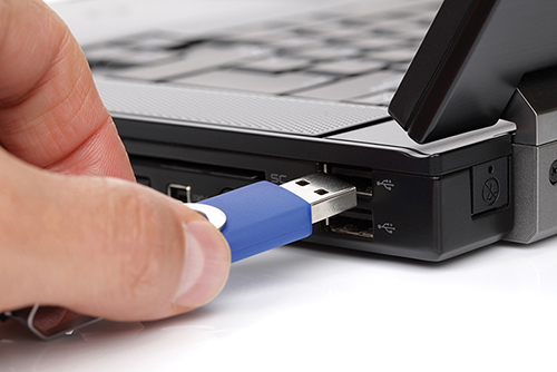
FIGURE 5.6 Flash drive
© Brian A. Jackson/Shutterstock
Flash memory is also being used to build solid-state disks (SSDs) that can directly replace a hard disk. Because an SSD is all electronic and has no moving parts, it is faster and consumes less power than a hard disk. Even so, its storage elements can eventually wear out, meaning that it can suffer failures just as a hard disk can.
Touch Screens
We’ve seen how secondary memory devices provide locations in which to store programs and data used by the CPU. Other input/output (I/O) devices allow the human user to interact with an executing program. Many of these are commonplace—we often provide information through a keyboard and mouse, and we usually view information displayed on a monitor screen. Other input devices include bar code readers and image scanners; other output devices include printers and plotters.
Let’s examine one particular type of I/O device in some detail. A touch screen displays text and graphics like a regular monitor, but it can also detect and respond to the user touching the screen with a finger or stylus. Usually, an I/O device serves either as an input device or an output device. A touch screen serves as both.
You’ve probably seen touch screens used in a variety of situations such as information kiosks, restaurants, and museums. FIGURE 5.7 shows someone using a touch screen. These devices are most helpful in situations in which complex input is not needed, and they have the added benefit of being fairly well protected. It’s far better for a waiter at a restaurant to make a few choices using a touch screen than to have to deal with a keyboard, which has more keys than necessary (for the task) and may easily get damaged from food and drink.

FIGURE 5.7 A touch screen
© Denys Prykhodov/Shutterstock
A touch screen not only detects the touch, but also knows where on the screen it is being touched. Choices are often presented using graphical buttons that the user selects by touching the screen where the button is positioned. In this sense, using a touch screen is not much different from using a mouse. The mouse position is tracked as the mouse is moved; when the mouse button is clicked, the position of the mouse pointer determines which graphical button is pushed. In a touch screen, the location at which the screen is touched determines which button is pushed.
So how does a touch screen detect that it is being touched? Furthermore, how does it know where on the screen it is being touched? Several technologies are used today to implement touch screens. Let’s briefly explore them.
A resistive touch screen is made up of two layers—one with vertical lines and one with horizontal lines of electrically conductive material. The two layers are separated by a very small amount of space. When the top layer is pressed, it comes in contact with the second layer, which allows electrical current to flow. The specific vertical and horizontal lines that make contact dictate the location on the screen that was touched.
A capacitive touch screen has a laminate applied over a glass screen. The laminate conducts electricity in all directions, and a very small current is applied equally on the four corners. When the screen is touched, current flows to the finger or stylus. The current is so low that the user doesn’t even feel it. The location of the touch on the screen is determined by comparing the strength of the flow of electricity from each corner.
An infrared touch screen projects crisscrossing horizontal and vertical beams of infrared light just over the surface of the screen. Sensors on opposite sides of the screen detect the beams. When the user breaks the beams by touching the screen, the location of the break can be determined.
A surface acoustic wave (SAW) touch screen is similar to an infrared touch screen except that it projects high-frequency sound waves across the horizontal and vertical axes. When a finger touches the surface, the corresponding sensors detect the interruption and determine the location of the touch.
Note that a gloved hand could be used in resistive, infrared, and SAW touch screens, but cannot be used with capacitive screens, which rely on current flowing to the touch point.