
All of us have worked with, or at least heard about, STP (Spanning Tree Protocol). The reason I call this recipe Analyzing Spanning Tree Protocols is because there are three major versions of it as follows:
- Spanning Tree Protocol (STP): This is an IEEE 802.1D standard from 1998 called 802.1D-1998
- Rapid Spanning Tree Protocol (RSTP): This is an IEEE 802.1W standard from 2001, later added to 802.1D, called 802.1D-2004
- Multiple Spanning Tree (MST): This was originally defined in IEEE 802.1S and later merged into IEEE 802.1Q
There are also some proprietary versions from Cisco and other vendors. In this recipe we will focus on the standard versions, and learn how to troubleshoot problems that might occur during STP/RSTP/MST operations.
The best way to find out STP problems is to log in to the LAN switches and use the vendor's commands (for example, Cisco IOS or Juniper JUNOS CLI) to find and fix the problem. If you have properly configured SNMP on your network device, you will get all the messages on the management console.
The purpose of this recipe is to see how to use Wireshark for this purpose, even though we still recommend to use it as a second line tool for this purpose.
So just open your laptop, start Wireshark, and start capturing data on the LAN.
There are several things to notice in a network regarding STP:
- Which STP version is running on the network?
- Are there any topology changes?
Wireshark will provide you with the version of the STP type (STP, RSTP, or MST) running on the network by looking at the Bridge Protocol Data Units (BPDUs). BPDUs are the update frames that are multicast between switches.
The protocol versions are:
- For STP, protocol version ID equals 0
- For RSTP/MST, the protocol version ID equals 3
When you monitor STP operations, you may be concerned when you see many topology changes. Topology changes are normal in STP, but too many of them can have an impact on network performances.
A topology change happens when a new device is connected to the network. You can see a topology change in the following screenshot:

When you see too many topology changes, configure the LAN switch ports that are connected to hosts, which do not support STP, (typically, end stations that users frequently power on and off) with the portfast feature (applied for Cisco switches; for other vendors, check the vendor's manual).
Tip
In the old STP (IEEE 802.1d), after connecting a device to a switch port, it takes the switch around a minute to start and forward packets. This can be a problem when a client tries to log in to the network servers during this period of time. The portfast feature forces the port to start forwarding within a few seconds (usually 8 to 10), in order to prevent these kinds of problems.
If topology changes continue, check what can be the problem and who is causing it.
Spanning Tree Protocol prevents a loop in the local area networks. A loop can happen if you connect two or more switches with multiple connections as shown in the following figure:

Let's see how a loop is created:
- Station A sends a broadcast to the network. A broadcast can be an ARP, NetBIOS, or any other packet with all ffs in the destination MAC address.
- Since broadcasts are forwarded to all ports of the switch, SW 1 receives the broadcast from port 1 and forwards it to ports 2 and 3.
- SW 1 and SW 3 will forward the packets to their other ports, which will get them to ports 2 and 3 of SW 4.
- SW 4 will forward the packet from port 2 to port 3, and the packet coming from port 3 to port 2.
- We will get two packets circling endlessly: the one that has been forwarded to port 3 (the red arrows), and the one that has been forwarded to port 2 (the green arrows) of SW 1.
- Depending on the switch forwarding speed, we will get up to tens of thousands of packets that will block the network completely.
The Spanning Tree Protocol prevents this from happening by simply building a tree topology, that is, by defining a loop-free topology. Links are disconnected and brought back to service in the case of a failure.
In the following figure, we see how we initially connect all switches with multiple connections between them, and how STP creates the tree:

BPDUs are update frames that are sent by multicast between the LAN switches.
First, on the Ethernet level as we see in the following screenshot, the packet will be multicast from the source MAC of the switch sending the update:

The BPDU is carried by Ethernet 802.3 frame has the format as shown in the next diagram:

In the following table, you can see the fields in the STP frame:
Note that in the case of MST, an additional header will be added for the MST parameters.
In STP, the port states are as follows:
- Disabled: In this state no frames are forwarded and no BPDUs are heard
- Blocking: In this state no frames are forwarded, but BPDUs are heard
- Listening: In this state no frames are forwarded, but the port listens for frames
- Learning: In this state no frames are forwarded, but MAC addresses are captured
- Forwarding: In this state frames are forwarded, and MAC addresses are captured
The moment you connect a device to the LAN switch, the port goes through these stages and the time it takes is as follows:
- From Blocking to Listening takes 20 seconds
- From Listening to Learning takes 15 seconds
- From Learning to Forwarding takes 15 seconds
In RSTP and MST, the port states are as follows:
- Discarding: In this state frames are discarded
- Learning: In this frame no frames are forwarded, and MAC addresses are captured
- Forwarding: In this state frames are forwarded, and MAC addressesare captured
The entire port state transition from Discarding to Forwarding should take a few seconds, depending on the network topology and complexity.
For Spanning Tree debugging, the best thing is to get the data from a direct connection to the LAN switches. A well-configured SNMP trap to a management system can also assist in this task.
Some examples of STP packets are as follows:
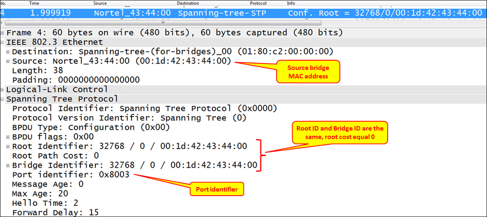
- In the following screenshot you see an STP frame. You can see that the source MAC address is a Nortel address, and in the BPDU itself you see that the root and the bridge identifiers are equal; this is because the bridge that sends the packet is the root. The port ID is 8003, which in Nortel switches indicates port number 3.
- In the following screenshot, you can see a Rapid STP BPDU. You can see here the protocol identifier that equals 2 and the port state that is designated.

- In the previous screenshot, you can see an example for MST. Here we see the MST extension right after the standard STP frame.
