
Effective packet analysis requires familiarity with the primary protocols in use in modern networks. In this chapter, we will review the most common protocols in their respective layers:
- Network layer protocols
- Transport layer protocols
- Application layer protocols
We'll cover the significant purpose and relevant fields to support network connectivity and/or application functionality in each protocol, as well a sampling of Wireshark capture and display filters for each protocol.
We reviewed the purpose of the OSI and DARPA reference models in Chapter 2, Networking for Packet Analysts. The visual depiction of their layers is repeated in the following diagram as a reference and summary of some of the primary protocols and where they fit into their respective layers:

Network layer protocols, also known as Internet layer protocols in the DARPA reference model, provide basic network connectivity and internetwork communications services. In this layer, you will predominantly find the IP protocol being used to get packets transported across the network, along with ARP, IGMP, and ICMP.
We covered the IP and ARP protocol packet header structures and fields in Chapter 2, Networking for Packet Analysts, so this information won't be repeated. However, basic Wireshark capture and display filters are provided here and also for the remaining protocols in the following sections:
Display filter(s): ip ip.addr==192.168.1.1 ip.src== ip.dst== ip.id > 2000
The Internet Group Management Protocol (IGMP) is used by hosts to notify adjacent routers of established multicast (one-to-any) group memberships. In other words, IGMP enables a computer that provides content (video feeds), for example, to provide such content to a distributed group of users using one set of the multicast address ranges (in the 224.0.0.0 to 239.255.255.255 class D multicast range). This multicast capability depends on routers that are capable and configured to support this service; clients must join the multicast group. When a host wants to start a multicast, it sends an IGMP Membership Report
message to the 224.0.0.2 (all multicast routers) address that specifies the multicast IP address for this particular group. Clients who wish to join or leave this group (so they can receive the multicast content) send an IGMP join or leave message to the router. The following table shows the various ranges for addresses:
|
Starting address range |
Ending address range |
Description |
|---|---|---|
|
|
|
These are reserved for special well-known multicast addresses |
|
|
|
These are globally-scoped (Internet-wide) multicast addresses |
|
|
|
These are locally-scoped and administered multicast addresses |
The following screenshot shows the significant fields in the IGMP protocol header:
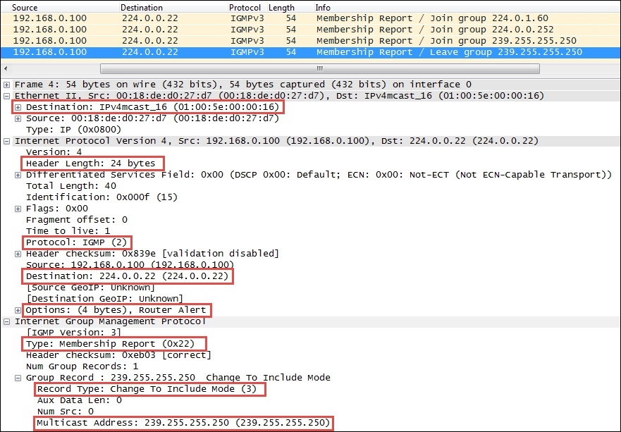
The preceding significant fields in the IGMP protocol header include:
- Type: This is a type of IGMP message. Type 22 is IGMPv3 Membership Report.
- Record Type: There are different types of Group Records. The value of Record Type 3 is Change To Include Mode, which indicates that content from the source device is to be forwarded to the in-group hosts by the multicast router.
- Multicast Address: This is the multicast IP address for a specific group.
You should also note the following interesting fields in the previous protocol layers:
- The Ethernet frame destination MAC address is one of a range of multicast MAC addresses (
01:00:5e:00:00:00 – 01:00:5e:7f:ff:ff) - The Protocol field in the IP header specifies IGMP 2
- The IP layer destination IP Address is
224.0.0.22, which is a reserved IGMPv3 multicast IP address
The IGMP protocol has multiple versions and is rather complex. Refer to the protocol references provided at the beginning of this chapter for more information.
The Internet Control Message Protocol (ICMP) is used by network devices such as routers to send error messages indicating that a requested service is not available, or a host or network router could not be reached. ICMP is a control protocol. This means that although it is transported as IP datagrams, it does not carry the application data—instead, it carries the information about the status of the network itself.
One of the most well-known uses of ICMP is to ping, wherein a device sends an ICMP echo request (Type 8, Code 0) packet to a distant host (via that host's IP address), which will (if the ICMP service isn't disabled or blocked by an intermediate firewall) respond with an ICMP echo reply (Type 0, Code 0) packet. Pings are used to determine whether the target host is available and can be reached over the network. By measuring the time that expires between ping requests and replies, we know the round trip time (RTT) delay time over the network path.
A variation of ping functionality is used to perform a traceroute (also known as traceroute), which is a list of the IP addresses of the router interfaces that packets traverse to get from a sending device to a target host or device. The traceroutes are used to determine or confirm the network path taken from a sending device to a target host or device.
A traceroute is accomplished by sending the ICMP echo request packets to a distant host just as in a normal ping, but with modifications to the Time-to-Live (TTL) field in the IP header of each packet. The traceroute function takes advantage of the fact that each router in a network path decrements the TTL value in a packet by 1, so as the packet traverses, the routers in a path and the TTL value will decrease accordingly along the way. If a router receives a packet with a TTL value of 1, it will send an ICMP TTL exceeded in transit (Type 11, Code 0) error message back to the sender (along with a copy of the request packet it received) and otherwise discard (not forward) the packet.
The traceroute works by sequentially setting the TTL in multiple ICMP request packets to 1, then to 2, then 3, and so on, which results in each router in the network path sending TTL exceeded error messages back to the sender. Since these returned messages are sent by the in-path router using the IP address of the interface where the ICMP packet was received, the traceroute utility can build and display a progressive list of router interface IP addresses in the path and the RTT delay to each router.
A sampling of the most commonly seen types of ICMP control messages, including their type and code (subtype) numbers, are provided in the following table:
|
Type |
Code |
Description |
|---|---|---|
|
0 |
0 |
This indicates echo reply (ping) |
|
3 |
0 |
This indicates destination network unreachable |
|
3 |
1 |
This indicates destination host unreachable |
|
3 |
4 |
This indicates fragmentation required and do not fragment bit set |
|
3 |
6 |
This indicates destination network unknown |
|
3 |
7 |
This indicates destination host unknown |
|
5 |
0 |
This indicates redirect datagram for the network |
|
5 |
1 |
This indicates redirect datagram for the host |
|
8 |
0 |
This indicates echo request (ping) |
|
11 |
0 |
This indicates TTL expired in transit (seen in traceroutes) |
The Wireshark packet details fields for the ICMP packet illustrated in the following screenshot depict a Time-to-live exceeded message as seen in a typical traceroute capture:

The following points are significant to analyze this packet:
- The source IP address seen in the IPv4 header summary is 10.192.128.1, which is the IP address of the router interface sending the ICMP message to the originator, 192.168.1.115
- The ICMP packet is Type 11, Code 0 (TTL exceeded in transit)
The second set of IPv4 and ICMP headers that follow the first IPv4 and ICMP headers are copies of the original packet transmitted by the sender. This copy is returned to allow determination of the packet that caused the ICMP message. The significant points in the packet details of this ICMP message copy include:
- The target destination IP address, where the echo request packet was intended to be sent (and would have been if the TTL value hadn't been altered) is
205.251.242.51. - The TTL value was 1 when this packet reached the
10.192.128.1router interface. This packet cannot be forwarded, resulting in the TTL exceeded message being sent back to the sender. - The original ICMP packet was a Type 8, Code 0 echo request message.
- The Header Data section of the ICMP packet for the echo requests and replies will include a 16-bit identifier and 16-bit sequence number, which are used to match echo replies to their requests.
Another common use of ICMP is to redirect a client to use a different default gateway (router) to reach a host or network than the gateway it originally tried to use. In the ICMP Redirect packet depicted in the following screenshot, a number of packet fields should be noted:
- The source IP address of the ICMP redirect packet is
192.168.1.1, which was the client's default gateway; this is the router sending the redirect packet back to the client - The ICMP Type is 5 (Redirect) and Code is 1 (Redirect for host)
- The gateway IP address that the router
192.168.1.1is telling the client to use to reach the desired target host is192.168.1.2 - The IP address of the target host was
10.1.1.125
The following screenshot shows the ICMP Redirect packets:

The Internet Protocol Version 6 (IPv6) is the latest version of Internet protocol, and although it is in its earliest stages of adoption, it is intended to eventually replace IPv4—mostly to alleviate the shortage of IP addresses that can be assigned to network devices. IPv4, with its 32-bit address space, provides approximately 4.3 billion addresses, nearly all of which have been assigned to companies and private interests worldwide.
IPv6 utilizes a 128-bit address space, which allows 2128 or approximately 3.4 x 1038 addresses; that number is 340,282,366,920,463,463,374,607,431,768,211,456 unique addresses.
The 128 bits of an IPv6 address are represented in eight groups of 16 bits each, written as four hexadecimal digits separated by colons (:). An example of an IPv6 address is 2001:0db8:0000:0000:0000:ff00:0042:8329.
For convenience, an IPv6 address may be abbreviated to shorter notations by application of the following rules, wherever possible:
- One or more leading zeroes from any groups of hexadecimal digits are removed; this is usually done to either all or none of the leading zeroes. For example, the hexadecimal group 0042 can be converted to just 42.
- Consecutive sections of zeroes are replaced with a double colon (::). The double colon may only be used once in an address, as multiple use would render the address indeterminate. A double colon must not be used to denote a single section of omitted zeroes.
An example of applying these rules to IPv6 addresses is as follows:
- Initial address:
2001:0db8:0000:0000:0000:ff00:0042:8329 - After removing all leading zeroes:
2001:db8:0:0:0:ff00:42:8329 - After omitting consecutive sections of zeroes:
2001:db8::ff00:42:8329
The 128 bits of an IPv6 address are logically divided into a network prefix and a host identifier. The Class Inter-Domain Routing (CIDR) notation is used to represent IPv6 network prefixes, for example, 2001:DB8:0:CD30::/64 represents network 2001:DB8:0000:CD30::.
There are three basic types of IPv6 addresses:
- Unicast: These packets from one-to-one device use a single interface address. Unicast addresses can be of one of the following three types:
- Global Unicast: This is routable to and over the Internet. Global Unicast addresses generally start with
2xxx(such as2000::/3). - Link-local: This is automatically assigned to an interface and used on the local network link; this is not routable to the Internet, much like a MAC address. Link-local Unicast addresses start with
FE80(FE80::/10). They are automatically assigned to an interface when it is initialized using an algorithm that uses a rearranged version of the NIC's 48-bit MAC address in the IPv6 address and are used to communicate on the local link. These addresses are not routable. IPv6 uses link-local addresses for neighbor discovery functions. - Unique local: This is not routable to the Internet, but it is routable within an enterprise (similar to IPv4 private addresses). Unique local Unicast addresses start with
FC00(FC00::/7). This block of addresses is reserved for use in private IPv6 networks.
- Global Unicast: This is routable to and over the Internet. Global Unicast addresses generally start with
- Multicast: These are packets from one-to-many devices. Multicast addresses start with
FFxx. An example of a multicast address isFF01:0:0:0:0:0:0:101, which can be shortened toFF01::101. There is no broadcast address in IPv6; multicasts are used as a replacement. Some well-known multicast addresses are shown in the following table:Address
Description
Scope
ff01:0:0:0:0:0:0:1All nodes address
Interface-local (spans only a single interface on a node useful only for loopback transmission of multicast packets)
ff02:0:0:0:0:0:0:1All nodes address
Link-local (all nodes on the local network segment)
ff01:0:0:0:0:0:0:2All routers address
Interface-local
ff02:0:0:0:0:0:0:2All routers address
Link-local
ff05:0:0:0:0:0:0:2All routers address
Site-local (spans a single site)
ff02:0:0:0:0:0:1:2DHCPv6 servers/agents
Link-local
ff05:0:0:0:0:0:1:3DHCPv6 servers/agents
Site-local
- Anycast: These packets are from one to the nearest of a group of interfaces. There is no special addresses scheme for Anycast addresses; they are similar to Unicast addresses. An Anycast address is created automatically when a Unicast address is assigned to more than one interface. Anycast addresses can be used to set up a group of devices so that any one of the group devices can respond to a request sent to a single IPv6 address.
Further discussion of IPv6 addressing would cover quite a number of additional features, which are beyond the scope of this book. The reader is encouraged to research IPv6 addressing further online and/or by reading Request For Comments (RFC) 4291 (IP Version 6 Addressing Architecture).
An example of an IPv6 protocol header is illustrated in the following screenshot:

The IPv6 header fields are similar to many IPv4 headers and the fields include:
- Version: This is the IP version number, 6 for IPv6.
- Traffic class: This is similar to the IPv4 DiffServ field; it is used to identify different classes or priorities of IPv6 packets.
- Flow label: These are used to identify sequences of packets that are labeled as a set. An IPv6 flow is defined by the 20-bit Flow Label field and the source and destination IPv6 address fields.
- Payload length: This is the length of the IPv6 payload, not including any packet padding.
- Next header: This field indicates what's coming next in the packet. This is equivalent to the IPv4 Protocol field. In the preceding example, the next layer is a normal TCP (6) header.
- Hop limit: This field is roughly equivalent to the Time To Live field in IPv4; it is decremented by one by each device that forwards the IPv6 packet. When the value reaches one, the packet cannot be forwarded.
- Source and Destination addresses: These are the 128-bit IPv6 source and destination addresses.
IPv6 supports extension headers that provide additional information fields and that also extend the length of the IPv6 header. There is specific Next Header code that indicates the presence of this added functionality.
As part of the transition to IPv6, the current TCP/IP devices support dual stacks (IPv4 and IPv6 simultaneously) and the ability to encapsulate and tunnel IPv6 packets inside IPv4 packets so that they can be routed by IPv4 networks. The three of the most popular encapsulation methods are:
- 6to4 tunneling: In this tunneling method, an IPv6 header follows an IPv4 header; the Protocol field of the IPv4 header will contain
41(IPv6), and the source IPv6 address in the IPv6 header will start with2002. - Teredo: In this tunneling method, an IPv6 header is encapsulated inside a UDP packet. This method was developed to accommodate NAT devices that do not handle protocol 41. Teredo tunneling can be identified in the UDP packet header by a destination port of
3544. - ISATAP: This tunneling method uses a locally assigned IPv4 address to create a 64-bit interface identifier. For example, in ISATAP, the IPv4 address
24.6.173.220becomes::0:5EFE:1806:addc. ISATAP encapsulates IPv6 headers within IPv4 as in 6to4 tunneling.
Internet Control Message Protocol Version 6 (ICMPv6) is an integral part of IPv6, and the base protocol must be fully implemented by every IPv6 node. ICMPv6 provides services for an IPv6 environment that are provided by other distinct protocols in an IPv4 environment, such as Neighbor Solicitation to replace ARP.
The following table contains some of the common ICMPv6 packet types:
An example of a Neighbor Solicitation ICMPv6 packet is shown in the following screenshot:

The significant fields in this packet include:
- Next Header: This field contains 58, which indicates that the next protocol header is to be ICMPv6.
- IPv6 Source Address: The presence of an unspecified address (::) indicates this is a Duplicate Address Detection packet.
- IPv6 Destination Address: This is basically a multicast address.
- ICMPv6 Type: This is a Neighbor Solicitation message using Type 135.
- ICMPv6 Code: This is the subtype for Neighbor Solicitation messages; this will be 0.
- ICMPv6 Target Address: This is the address the host wants to use. If another node on the network is already using this address, they will respond accordingly.