
Packet analysis is all about analyzing how applications transfer useful data from point A to point B over networks. So, an understanding of how networks function is essential.
In this chapter, we will cover the following topics:
- Why the seven-layer OSI model matters
- IP networks and subnets
- Switching and routing packets
- Ethernet frames and switches
- IP addresses and routers
- WAN links
- Wireless networking
The seven-layer OSI model will be mapped to the most common networking terms, and we'll review frames, switching, IP addressing, routing, and a few other networking topics of interest. The goal is to develop a mental model of networking that lends itself well to packet-level analysis.
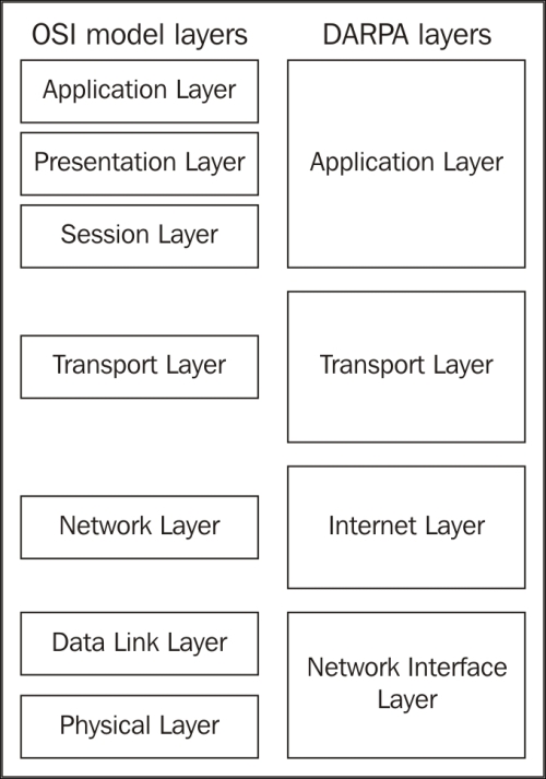
The Open Systems Interconnections (OSI) reference model is an industry recognized standard developed by the International Organization for Standardization (ISO) to divide networking functions into seven logical layers to support and encourage (relatively) independent development while providing (relatively) seamless interconnectivity between each layer from different hardware/software environments, platforms, and vendors. There's also a somewhat simpler four-layer Defense Advanced Research Projects Agency (DARPA) model that maps to the OSI model, but the OSI version is the most commonly referred to. I'll reference both models when discussing the various layers.
The following diagram compares the OSI and DARPA reference models:
Unless you're in the business of writing protocols, there's no need to study any of the seven layers in great depth, but it is helpful to understand them conceptually because these layers are referred to by the industry and your IT peers.
More importantly, it's essential that you know where and how these layers and their associated protocols are presented in Wireshark's Packet Details pane. We'll cover the layers from this aspect to help you remember them and get the most use from the discussion.
Network protocols, like the OSI layers, are a set of industry standard rules and designs used to exchange messages and data between computers and applications. In any discussion about OSI layers, you are directly or indirectly referring to the protocols associated with a given layer—the most commonly known protocols are IP, UDP, TCP, HTTP, and so on—and the significant functions they perform.
For example, you'll often hear the terms network layer and IP layer used interchangeably, and it is assumed and understood that you are talking about the layer and the associated protocol that contains and uses IP addresses to route packets from point A to point B across the network. The discussions that follow will tie the OSI and DARPA layers to their associated protocols.
As we cover the OSI layers starting from layer 1 and working up to layer 7, I'll outline how each layer's associated protocol(s) are displayed in Wireshark and/or used in networking hardware. The mental model you develop from this approach should be the most accurate and useful for packet analysis.
The physical layer encompasses the electrical characteristics and mechanical standards to get data bits transmitted from a computer's Network Interface Card (NIC) to a switch port or between switch and router ports. The most common standards, terms, and devices you'll encounter at this layer include the following:
- Ethernet: This is a family of networking technologies for local area networks (LANs).
- RJ-45: These are 8-pin modular connectors found on both ends of a copper Ethernet cable that are plugged into the NIC on a computer and a wall jack or switch port
- Cat 5 (Cat 5e or Cat 6) cables: These are Ethernet cables that use twisted-pair copper wires. "Cat" stands for the category of cable and reflects its quality and data speed capabilities.
- 100Base-T, 1000Base-T, and 1000Base-LX: These represent a particular Ethernet standard. 100Base-T is 100 Mbps over twisted-pair cable using RJ-45 connectors, 1000Base-LX is 1000 Mbps over fiber, and so on.
- Single-mode and multimode fiber optic cables: These use pulses of light from solid-state LEDs or lasers to transmit data bits.
The Ethernet standards used to connect NICs to switches are also used to connect switches together and to connect switches to routers or other network devices, although the cables and connectors used may vary depending on cable type and speed.
There are other layer 1 standards in common use, including 802.11 Wireless, Frame Relay, and ATM; the last two are used in long distance wide area networks (WANs).
The data-link layer organizes raw bits from the physical layer (typically Ethernet) into frames, which is the first manifestation of what is generally called a packet that you'll see in Wireshark. This layer is a dividing line between physical networking, electrical/mechanical standards, and the logical structures (protocols) used to format and transmit, receive, and decode packets of data in the higher layers.
In the DARPA reference model, the physical and data-link OSI layers are combined and called the network interface layer. The significant features and functions of this layer (for Ethernet II frames) include:
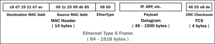
- Media Access Control (MAC) addresses: These are the network addresses used in LANs. They are 6-byte network hardware addresses burned into memory chips on NICs, switches, routers, or other network device ports/interfaces:
- The first three bytes of a MAC address are assigned to and can be associated with a specific manufacturer. Wireshark has a list of these and can display MAC addresses as a combination of the manufacturer code and the last three bytes. The manufacturer creates a unique last-three-bytes address for every interface so that each MAC address is unique across the globe. (Although, an NIC might be programmed to use another arbitrary MAC address, which is done for MAC spoofing for malicious attacks. But this is a very bad idea as another card may be using the same address and can cause a loss of data and some very confusing packet switching problems.)
- Ethernet frames include a destination and source MAC address. MAC addresses are used to switch (not route—we'll make the distinction shortly) frames between computers on the same LAN or between computers and a router or other device port on a LAN.
- Type (or EtherType) field: This indicates the next higher protocol layer (typically IP (0800) or ARP (0806)). Wireshark uses this to determine the next protocol dissector to apply in packet decodes.
- Payload: This is the packet or datagram carried by the Ethernet frame.
- The frame check sequence: This is a 4-byte Cyclic Redundancy Check (CRC) error-detection code calculated from all the bits in a frame and added to the end of the frame. This is used to detect frames that have been corrupted usually because of faulty cables, noise induced on the wires in a cable from outside electrical signals, and so on. When a frame is received, this code is recalculated based on the bits received and compared to the FCS field. The bad frames are then discarded.
The following diagram illustrates the layout of the fields in an Ethernet frame:
A key point here—and this is important to understand—is that Ethernet frames and their MAC addresses are only able to transmit frames between devices on the local area network (LAN and IP subnet) they belong to.
Routers form the boundary between LANs by virtue of their IP subnet (subnetwork) addressing. All the devices belonging to the same IP subnet are part of the same LAN, and getting packets to or from a different subnet requires a router.
Once a frame enters a router port to get routed to a different/distant network, the Ethernet frame with its MAC addresses and FCS is stripped off and discarded. The payload inside the frame is routed to the port and it will leave on its way to the next device, and another frame with a different MAC address and recalculated FCS is created to encase the packet. This frame is then transmitted to the next destination.
The network devices that work at this layer—usually switches—are commonly referred to as layer 2 devices or layer 2 switches.
Finally, you should be aware that layer 2 switches can support several networking enhancements such as Virtual LAN (VLAN) and Class of Service (CoS) tagging, which is accomplished by adding a 4-byte 802.1Q field between the MAC addresses and EtherType field. You might see these frames between switches (but not on user ports).
VLAN is a layer 2 solution that allows administrative partitioning of various ports on a switch into separate broadcast domains. Devices located on different VLANs are effectively isolated from each other as if they were on separate physical networks. VLANs can be dispersed across multiple switches without running separate cables for each VLAN if the switches support VLAN tagging. Communication between devices on separate VLANs generally requires using a router.
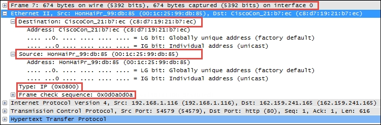
In the following Wireshark packet details screenshot, the Ethernet II frame Destination and Source MAC addresses, Type (indicating that the next layer protocol is IP), and Frame check sequence are circled, as is the Frame summary.
The following screenshot highlights the significant fields of an Ethernet frame:
The network layer (called the Internet layer in the DARPA model) primarily handles the routing of packets across and to other networks along the path from source computers to destination hosts based on the destination IP address. The two most common protocols seen at this layer are Internet Protocol and Address Resolution Protocol.
The most common protocol in use at this layer is Internet Protocol Version 4 (IPv4), which includes several essential fields to accomplish the task of routing packets across networks:
- Differentiated Services (DiffServ): This field supports an enhancement to the IP that is generally called Quality of Service (QoS) and allows classification of certain types of traffic (voice, video, and so on) so that these packets can receive priority handling in cases of network congestion.
- Total length: This is the total length of the packet (minus the Ethernet MAC header).
- Identification (IP ID): This an incrementing number used to support fragmentation.
- Flags: These are used to support fragmenting (dividing a packet into two or more smaller ones) in case the large packets have to be divided into several smaller ones to traverse a packet-size-limited link. These flags along with the IP ID field values allow proper reassembly of the fragmented packets into the original.
- Fragment offset: If the Flag field is 1 (more fragments), the value in this field indicates the offset from the start of the original payload in bytes that this fragment packet contains.
- Time to Live (TTL): This is a "hop" or time counter that is decremented every time a packet passes through a router. If the TTL reaches zero, the packet is discarded. The primary purpose is to keep packets from living forever and crashing the network in the case of an inadvertent path loop.
- Protocol: This identifies the protocol in the IP packet's payload. Wireshark uses this to determine the next protocol dissector to apply to packet decodes.
- Source and destination IP addresses: These are the IP addresses of the sending machine and the ultimate destination machine. IP addresses are 4 bytes long and are represented as four octets (numbered 0 through 255 decimal) separated by periods.
In the following screenshot, the significant IPv4 fields are circled. These are the fields you'll want to inspect and be comfortable with when doing packet analysis at this layer.

Another protocol you'll see at the network layer is Address Resolution Protocol (ARP), which is used by a device to obtain the MAC address of another device when it only knows that device's IP address.
In the following Wireshark packet details screenshot, note that the Ethernet frame destination MAC address is Broadcast (ff:ff:ff:ff:ff:ff), Type is ARP (0x0806), and the station has provided its own MAC and IP address in the ARP protocol Sender fields (which other stations listen to and use to build a table of MAC and IP addresses). It provides the IP address of the target device and puts all zeros in the Target MAC Address field. The target device should return a similar ARP packet addressed to the requestor with its MAC address in the Sender field.
A station will send an ARP request only in the following situations:
- The station that requires a MAC address for a target device hasn't heard a previous broadcast of that station's MAC address, or its ARP table has timed out (ARP entries are only kept for a period).
- The station that requires a MAC address for a target device has calculated (from the target's IP address and its own subnet mask) that the target device should be on the same LAN. Otherwise, the station assumes the target device is on a different network and sends its first session initiation packet to the default gateway (router) MAC address based on the entry in the sending station's default gateway configuration setting. The default gateway will forward the packet to the appropriate egress port to route it to the destination.
- The station that needs to send a packet to a distant network doesn't know the MAC address of its default gateway (for example, just after a power-up).
The following screenshot highlights the significant fields of an ARP packet:

Other protocols utilized at this layer include Internet Control Message Protocol (ICMP), which is used to send network error messages between devices, and Internet Group Management Protocol (IGMP), which is used by hosts and adjacent routers to establish multicast (one-to-many) group memberships for network applications such as streaming video and gaming.
The transport layer, as it's called in both the OSI and DARPA models, is responsible for transporting packets of data in unique sessions between applications or a user and an application by means of port numbers. The combination of a device or user's IP address and that device or user's assigned port number (referred to as a socket) will be different from another devices or users' IP address and port numbers (on the client side).
If the source host for a packet is a server, the source port is likely to be a well-known number for standard applications and services, such as port 80 for HTTP.
The transport layer typically uses one of two protocols, User Datagram Protocol or Transmission Control Protocol, with the latter being the more prevalent for most applications.
The User Datagram Protocol (UDP) is a fairly simple protocol. It is considered an unreliable transport as there's no guarantee of packet delivery or ordering, but it has lower overhead and is used by time-sensitive applications such as voice and video traffic, as well as by network services applications such as DNS.
The UDP header is only 8 bytes long and consists of the following:
- Source and Destination port number:These are 2 bytes each.
- Length: This is the length of the UDP header plus the payload. This is a 2-byte field.
- Checksum: This is the 2-byte field used to check errors of the UDP header and data. If no checksum was generated by the transmitter, this will be all zeros.
The following screenshot shows the fields contained in a UDP header:

Unlike UDP, the Transmission Control Protocol (TCP) provides reliable delivery of data by detecting lost, duplicated, or out-of-order packets, requesting retransmission of lost data, or rearranging packets in the right order before delivering them to the application. TCP can also accept a large chunk of data from an application and handle getting the data transported to the other end reliably using multiple packets and reassembling them at the other end (as can UDP, but not reliably; the application has to determine and recover from lost packets).
The TCP header contents and length can vary depending on the options that may be in use, but in its simplest implementation, it consists of:
- Source and Destination ports (2 bytes each): These are well-known registered ports that are used (on servers) to access standard application services such as HTTP, FTP, SMTP, databases, and so on. Port numbers assigned to client/user sessions are usually in a higher number range and assigned sequentially.
- Sequence number (4 bytes): This is a number that represents the first octet in any given segment. Sequence numbers are initialized at the beginning of new sessions as a random number, and then incremented as data bytes and sent.
- Acknowledgment number (4 bytes): When the ACK flag bit is set, this field contains the next sequence number expected from the sender, which in turn acknowledges receipt of all the bytes received up to that point.
Note
The use of sequence and acknowledgment numbers are how the TCP ensures reliable delivery of data by tracking the number and order of received bytes.
Sequence and acknowledgment numbers are large and difficult for humans to follow; Wireshark can convert and display these as relative values that start with 0 at the beginning of a session to make it easier to inspect them and relate the values to the number of bytes transmitted and received.
- Flags (9 bits): These bits are used to control connection setups, terminations, and flow control mechanisms.
- Window size (2 bytes): This indicates the current size of the buffer on this host used to store received data until it can be handed off to the receiving application. This information lets the sending host adjust data flow rates in case of network or host congestion.
The following screenshot highlights the significant fields of a TCP header:

The session layer handles setting up, controlling, and ending sessions within an application between two computers. This is not necessarily the same thing as, for example, a TCP connection, although the two will be related. The application sessions can span and outlive multiple network connections. An example of a networking protocol that operates at this layer is Network Basic Input/Output System (NetBIOS).
The presentation layer converts incoming and outgoing data from one format to another and handles encryption/decryption and/or compression if any of these are required. The presentation layer is also responsible for the delivery and formatting of information to the application layer for further processing or display. An example of a presentation service would be the conversion of an EBCDIC-coded text computer file to an ASCII-coded file.
The application layer, which may (or may not) perform separate functions from the application itself, handles message formatting, human to machine interfaces, and so on. This layer represents the services that directly support applications such as software for file transfers, database access, e-mail, and so on.
In many widely used applications, no distinction is made between the presentation and application layers. For example, HyperText Transfer Protocol (HTTP), which is generally regarded as an application-layer protocol, has presentation-layer aspects such as the ability to identify character encoding for proper conversion, which is then done in the application layer.
In the DARPA model, the OSI layers 5-7 are combined into an application layer. From a packet analysis standpoint, the particular manifestations and visibility (in Wireshark) of the functions in the top layer(s) will vary depending on the applications and specific protocols employed to support them.
The following diagram summarizes the OSI and DARPA layers and how various networking protocols and services align with these layers and each other:

You may have observed by now that packets encapsulate various protocols into successive layers, just like peeling an onion. An Ethernet frame contains a datagram payload; this datagram is a packet with an IP header and payload. The IP packet payload consists of a TCP header and data segment, which in turn may contain an HTTP header and payload. This encapsulation is easier to visualize when working within Wireshark's Packet Details pane.