
9
UNDERSTANDING FUNDAMENTAL PROCESSES IN CATALYTIC HYDROGENATION REACTIONS
Yongkui Sun*
Department of Process Research, Merck & Co., Inc., Rahway, NJ, USA
Carl LeBlond
Department of Chemistry, University of Pennsylvania, Indiana, PA, USA
9.1 INTRODUCTION
Hydrogenation is a powerful methodology in synthetic organic chemistry and has been broadly employed by organic chemists in drug synthesis. Heterogeneous‐catalyzed hydrogenation has been very popular traditionally and continues to play a critical role in modern organic synthesis [1, 2]. Hydrogenation by homogeneous catalysts, particularly asymmetric hydrogenation, is gaining momentum in applications in the pharmaceutical industry. Since the pioneering work in the development of chiral catalysts for asymmetric hydrogenation by William Knowles in late 1960s and the first commercial application of asymmetric hydrogenation in the early 1970s by Monsanto in the production of the anti‐Parkinsonian drug L‐DOPA [3, 4], asymmetric hydrogenation has developed into a powerful chemical transformation, achieving enantioselectivities matching those previously seen only in enzymatic processes. Over the ensuing two to three decades, there has been rapid development in the science and technology of asymmetric hydrogenation. One of the key milestones in the development of this chiral technology was the discovery of BINAP in the 1980s by Ryoji Noyori and coworkers [5], which significantly broadened the scope of utility of asymmetric hydrogenation [6]. A recent special issue of the Accounts of Chemical Research documented the growing application of asymmetric hydrogenation in the pharmaceutical industry [7].
Hydrogenation reactions in the liquid phase are complex processes. Even for a homogeneously catalyzed hydrogenation for which the catalyst and the substrate are fully soluble in the solvent, the hydrogenation process is heterogeneous in nature since the dihydrogen reducing reagent H2 is in a different phase. In addition to the catalytic reaction occurring on the catalyst, there are a number of mass transfer processes that can exert direct influence on the outcome of the catalytic reaction itself.
In the case of heterogeneous catalysis, the mass transfer processes include H2 transport across the gas–liquid and the liquid–solid interfaces before the molecular H2 chemisorbs dissociatively on the metal catalyst, as well as H2 diffusion inside the pore structure of the catalyst particles. A schematic depicting the mass transfer processes (pore diffusion not displayed) is shown in Figure 9.1, along with the corresponding H2 concentration profile. Among the mass transfer processes, the gas–liquid mass transfer needs significant attention in designing a hydrogenation process because it can have profound impact on the performance of the hydrogenation reaction [8], and it is greatly affected by agitation, reactor design and configuration, solvent properties such as viscosity, and solvent fill level. Mass transfer of H2 across the liquid–solid interface and through the pore structure in the catalyst particles is often dominated by the physical characteristics of the catalyst, i.e. particle size, shape and support material, and density and pore structures. While agitation intensity and reactor design can influence their kinetics, for catalytic system in which the diameter of the catalyst particle is less than 50 μm, the effects become minimal once a uniform catalyst suspension is achieved. It is not the intention of this chapter to review all the mass transfer issues encountered in hydrogenation reactions carried out in slurry reactors [9]. Instead, this chapter focuses only on the simple but crucial hydrogen gas–liquid mass transfer issue and its impact on the development of hydrogenation processes.
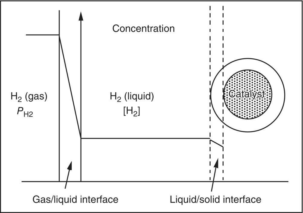
FIGURE 9.1 A schematic of hydrogen mass transfer processes across the gas/liquid and liquid/solid interfaces during a heterogeneously catalyzed hydrogenation reaction. Also plotted is a schematic of the hydrogen concentration profile.
9.2 SOLUTION HYDROGEN CONCENTRATION DURING HYDROGENATION REACTIONS, [H2]
When gas–liquid delivery is the dominant mass transfer step, the pathway followed by H2 from the gas phase to its incorporation into the product in catalytic hydrogenation reactions using either a homogeneous or a heterogeneous catalyst may be simply described as follows:
where kLa is the mass transfer coefficient for the H2 mass transfer across the gas–liquid interface and kr is the rate coefficient of the catalytic reaction. The intrinsic kinetics in the catalytic hydrogenation is a function of concentrations of the substrate, the catalyst, and the dissolved H2, in addition to other factors such as the temperature. In developing a chemical process, one is normally demanding in the knowledge of the concentration of the substrate and tries to follow [substrate] via various means during the course of the reaction. One is frequently, however, less demanding in the knowledge of the solution concentration of hydrogen, [H2], due, in most part, to an assumption that [H2] equals the equilibrium solubility of hydrogen, [H2]sat, at the temperature and pressure of the reaction.
The assumption holds, however, only when the rate of H2 mass transfer is far greater than that of hydrogenation reaction itself. While [H2]sat is fixed at a constant gas‐phase H2 pressure, [H2] may vary widely from nearly zero to nearly saturation, depending critically upon the relative magnitude of the rate of H2 mass transfer from the gas to the liquid phase and the rate of reactive H2 removal from the liquid phase due to the hydrogenation reaction. This is readily seen from a mass balance of the dissolved H2 below:
The first term to the right of Eq. (9.2) is the rate of H2 mass transfer from the gas to the liquid phase, and the second term the rate of reactive removal of the dissolved H2 from the liquid phase by the catalytic hydrogenation.
The kinetics of H2 mass transfer resembles that of the familiar first‐order chemical reaction and may be characterized by a single parameter, the mass transfer coefficient kLa. A comparison of the characteristics, including the kinetic expression and the maximum rate, between these two processes is given in Table 9.1. The significance of the mass transfer coefficient kLa is that it is the kinetic factor that dictates the maximum rate of mass transfer of hydrogen across a gas–liquid interface, i.e.
in conjunction with the thermodynamic factor [H2]sat.
TABLE 9.1 A Comparison of the Characteristics of Gas–Liquid Mass Transfer and a First‐Order Chemical Reaction
| Gas–Liquid H2 Mass Transfer | First‐Order Reaction | |
| Kinetic expression | ||
| First‐order rate coefficient (s−1) | kL a | kr |
| Maximum rate |
While kr is an intrinsic kinetic property of the catalytic system, kLa is strongly affected by characteristics of the reactor vessel, including reactor type, configuration, liquid fill level, viscosity, and particularly agitation speed. At a constant H2 pressure, the magnitude of [H2] during the reaction depends critically upon the relative magnitude of these two rate coefficients. In a situation where the kinetics of the mass transfer is much slower than the intrinsic reaction kinetics, i.e.
or
[H2] deviates significantly from [H2]sat, and the solution is starved for H2. In other words, the effective H2 pressure, i.e. the pressure that the catalyst experiences, is lower than the H2 pressure in the gas phase. Under extreme hydrogen‐starved conditions, [H2] or the effective H2 pressure may approach zero. In this case, the reaction becomes entirely limited by the mass transfer instead of by the catalytic processes on the catalyst, and the observed reaction rate equals the maximum rate of H2 mass transfer. On the other hand, if the kinetics of mass transfer is much faster than the intrinsic reaction kinetics, i.e.
or
[H2] approaches [H2]sat, and the effective H2 pressure approaches the pressure in the gas phase.
Assuming that [H2] in Eq. (9.2) varies slowly with time, the lowest value of [H2] may be expressed as
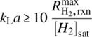
To ensure that the solution is nearly saturated with H2 throughout the entire course of the reaction and the observed rate is representative of the kinetics intrinsic to the catalytic system under the specified hydrogen pressure, a rule of thumb is that the maximum intrinsic reaction rate should be less than 10% of the maximum H2 delivery rate:

Equation (9.6) shows
when the 10% rule of thumb is satisfied.
9.3 IMPACT OF kLa ON REACTION KINETICS AND SELECTIVITY
As shown in Section 9.2, even when the pressure in the gas phase is specified, the reaction conditions could in actuality be unspecified due to uncharacterized deviation of [H2] from [H2]sat as a result of a lack of knowledge of the hydrogen mass transfer coefficient kLa. Under the unspecified conditions, rate measured reflects kinetics at an unknown [H2] instead of the intended constant [H2]sat. The kinetic data obtained under such conditions are not helpful and can even be harmful to the development of scalable processes. Irreproducibility in rate from reactor to reactor may be observed under seemingly identical reaction conditions due to different mass transfer coefficients in different reactors. A process developed under such conditions may pose safety as well as selectivity problems in scale‐up. In addition, the deviation of [H2] from [H2]sat may cause irreversible alteration of the catalyst properties. The catalyst may be deactivated due to lack of hydrogen atoms on the catalytic surface, which not only reduces the catalytic activity but also may change the selectivity of the catalyst in undesirable manners.
In addition, selectivity of the hydrogenation reactions may be strongly influenced by mass transfer by virtue of the intrinsic dependence of the selectivity on [H2], the effective pressure that the catalyst experiences. Many reactions exhibit strong dependence of selectivity on hydrogen pressure. Examples include the [Rh(dipamp)]+‐catalyzed asymmetric hydrogenation of α‐acylaminoacrylic acid derivatives [10], asymmetric hydrogenation of γ‐geraniol and geraniol catalyzed by BINAP-Ru(II) [11], and enantioselective hydrogenation of ethyl pyruvate over cinchonidine‐modified Pt [12]. In the case of asymmetric hydrogenation of γ‐geraniol catalyzed by (S)-BINAP-Ru(II), the enantioselectivity to (R)‐β‐citronellol decreases precipitously from 90%ee to nearly racemic with increasing effective H2 pressure from nearly zero to 100 psia. The case of asymmetric hydrogenation of geraniol is even more dramatic. The enantioselectivity flips from an ee of 93%(R) to 91%(S) when the H2 effective pressure changes from 100 psia to nearly zero due to the presence of the competitive isomerization of geraniol to γ‐geraniol under the hydrogenation conditions (Figure 9.2) [13]. In all these cases, even at constant H2 gas‐phase pressure, uncharacterized deviation of [H2] from [H2]sat as a result of H2 mass transfer limitations translates into unpredictable selectivity.
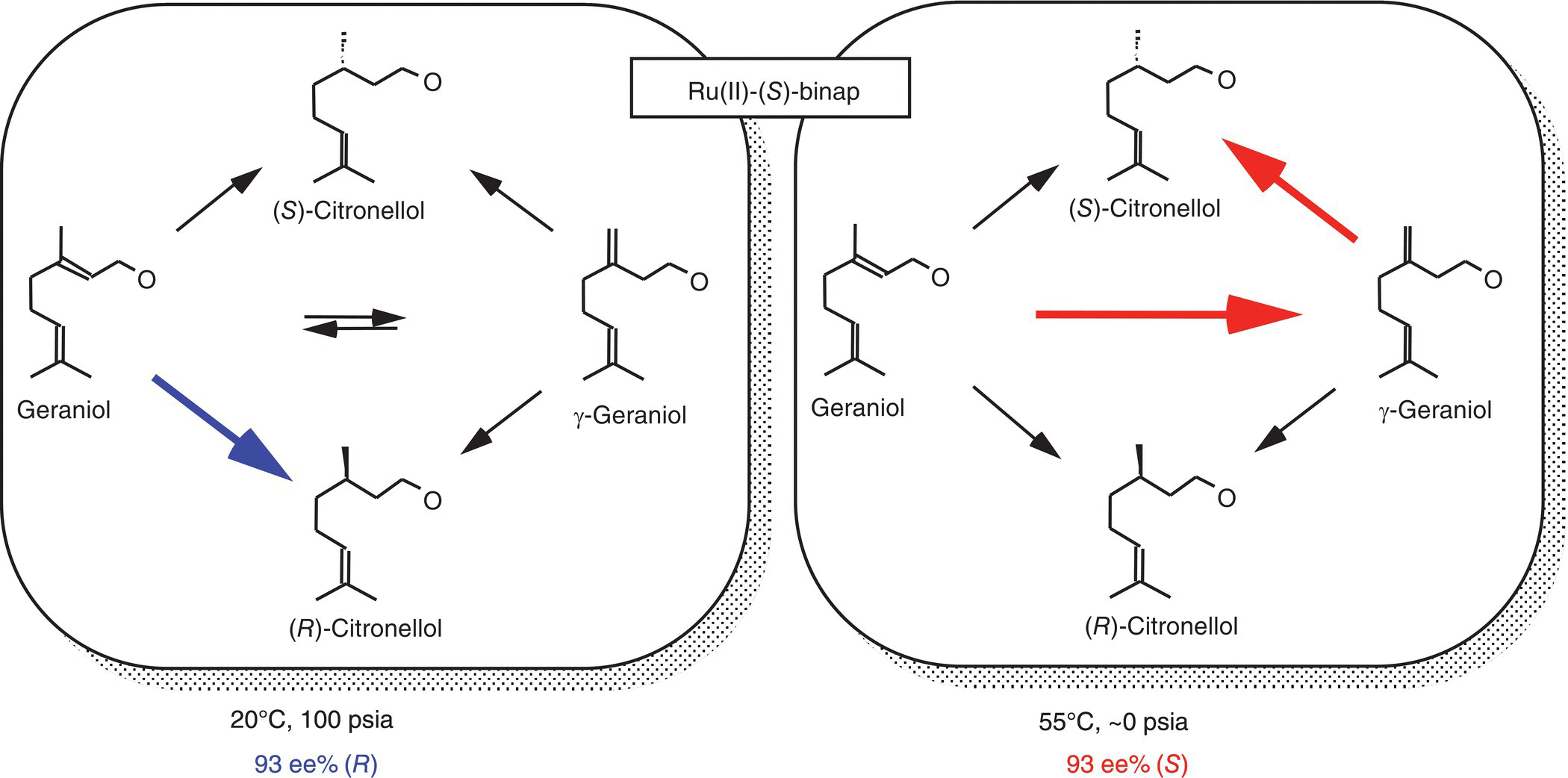
FIGURE 9.2 Striking dependence of enantioselectivity in the asymmetric hydrogenation of geraniol as a result of the interplay of rate processes in the isomerization/hydrogenation network.
It is interesting to note that the mass transfer limitations may work for or against the desired selectivity, depending on how the selectivity is related to [H2]. For instance, at a constant gas‐phase pressure, mass transfer limitations help to enhance the enantioselectivity of the (S)-BINAP-Ru(II)‐catalyzed asymmetric hydrogenation of γ‐geraniol to (S)‐citronellol, in which case the selectivity increases with decreasing pressure.
The effect of the interplay between the mass transfer and the intrinsic rate processes on kinetics and selectivity for reactions carried out at constant H2 pressure is further demonstrated in Figure 9.3, using as an example the enantioselective hydrogenation of ethyl pyruvate over cinchonidine‐modified Pt [8b]. The effects of the two extreme situations discussed above are graphically illustrated by the difference in the observed kinetics and enantioselectivity. At 400 rpm, the H2 mass transfer is much slower than the intrinsic hydrogenation rate (kLa = 4 × 10⁻³ s−1). [H2] is virtually zero. The kinetics, being completely limited by the rate of the H2 delivery across the gas–liquid interface instead of by the catalytic hydrogenation of ethyl pyruvate on the Pt surface, is independent of the substrate concentration and therefore exhibits zero‐order kinetic behavior. A process developed under these conditions would potentially run into safety issues when scaled up as the hydrogenation rate would change greatly with differences in the mass transfer coefficient kLa associated with large hydrogenators. At 2000 rpm, the mass transfer is no longer limiting the rate (kLa = 0.7 s−1); the solution is saturated with H2 at all times during the reaction, i.e. [H2] ≅ [H2]sat; and the rate is limited by the catalytic hydrogenation of ethyl pyruvate over Pt. Further increases in the mass transfer coefficient no longer change the rate profile. As a result, a picture of the intrinsic kinetics emerges. In addition to the kinetics, the mass transfer also influences selectivity by virtue of changing the availability of H2 that the catalyst experiences. Figure 9.3 shows that the enantioselectivity increases from 23 to 60 %ee due to a change in [H2] from starvation to saturation upon increasing the agitation speed from 400 to 2000 rpm.

FIGURE 9.3 Effect of hydrogen mass transfer on kinetics and enantioselectivity in the chiral hydrogenation of ethyl pyruvate over cinchonidine‐modified Pt. Except for the different stir rates, the two experiments were carried out under otherwise identical conditions (30 °C, solvent: 1‐propanol).
In developing a hydrogenation process, it is the intrinsic catalyst activity and selectivity, i.e. the catalytic behaviors under well‐defined conditions, which are of foremost concern, not those convoluted with the hydrogen mass transfer process. Obviously, it is not sufficient to specify H2 pressure alone in order to unravel kinetics and selectivity of a catalytic hydrogenation reaction intrinsic to the catalytic system. It is necessary to characterize the mass transfer properties of the hydrogenator and conduct the hydrogenation experiments according to the 10% “rule of thumb” as described by Eq. (9.7).
9.4 CHARACTERIZATION OF GAS–LIQUID MASS TRANSFER PROCESS
Section 9.3 described how the gas–liquid mass transfer process, characterized by the simple parameter kLa, can exert significant influence on the outcome and robustness of the hydrogenation process. It is not uncommon in the pharmaceutical industry, however, to see chemists and chemical engineers employ hydrogenation vessels for screening, scaling up, and commercialization of hydrogenation processes without characterizing their mass transfer coefficients. In this section, a simple practical procedure for measuring kLa is reviewed, and the examples are given for measuring kLa in a variety of hydrogenators at scales ranging from 100 ml to 760 gal in volume. Given the importance of the mass transfer coefficient, it is recommended that all hydrogenators, including those used for screening, for process development and scaling up, and for commercialization, be characterized in term of their mass transfer coefficients.
Among the methodologies available, the most straightforward one for measuring the gas–liquid mass transfer coefficient kLa is to measure directly the kinetics of nonreactive hydrogen uptake by the solution at various agitation speeds [14]. In this method, the solution is first degassed thoroughly by vacuum with the agitation on. The agitator is then turned off; hydrogen gas is introduced to the headspace of the hydrogenator to a pressure close to the hydrogenation pressure at which point the hydrogen line valve to the hydrogenator is closed. When the agitation commences, the pressure in the reactor is recorded as a function of time using a fast‐response pressure transducer. A schematic depicting the pressure drop in the headspace of the hydrogenator and the corresponding concentration rise of hydrogen in the liquid phase is shown in Figure 9.4. The rate at which the pressure decreases is directly related to the gas–liquid transfer rate, whereas the extent to which the pressure drops is related to the solubility of the gas in the liquid. The dependence of pressure P as a function of time t is governed by the simple first‐order rate equation below:

where
- Pi: the initial pressure
- Pf: the final pressure
- P0: the solvent vapor pressure.

FIGURE 9.4 Schematics of the pressure drop and the corresponding concentration rise in a kLa measurement experiment.
Typical pressure–time curves in the Metter Toledo's 1 L RC1 MP10 reactor are displayed in Figure 9.5a. They graphically illustrate the difference in mass transfer rates at agitation rates of 400 and 1000 rpm. Figure 9.5b shows the pressure plot obtained using the data in Figure 9.5a according to Eq. (9.9). The slope of the pressure plot yields kLa, which is 3.8 × 10⁻³ s−1 at 400 rpm and 0.24 s−1 at 1000 rpm. Another way to look at the difference in the mass transfer rates is a comparison of the “half‐life,” i.e. t1/2 = ln2/kLa. While reaching 50% of the hydrogen saturation concentration takes only approximately 3 seconds at 1000 rpm, it takes approximately 3 minutes at 400 rpm.
![Left: H2 pressure vs. time with 2 descending curves for 400 rpm with kLa = 3.8 × 10⁻³ (s−1) and for 1000 rpm with kLa = 0.24 (s−1). Right: (Pf/ Pi)ln[(Pi–Pf)/(P–Pf)] vs. time with 2 ascending lines for 400 rpm and 1000 rpm.](http://images-20200215.ebookreading.net/2/1/1/9781119285861/9781119285861__chemical-engineering-in__9781119285861__images__c09f005.gif)
FIGURE 9.5 Measurements of the H2 uptake kinetics in 1‐propanol (0.5 L) in the Mettler Toledo's 1 L RC1 MP10 reactor at 30 °C. (a) Hydrogen pressure drop as a function of time. (b) Corresponding plots of the pressure function in Eq. (9.9) vs. time. The slope is kLa.
The mass transfer coefficient can be strongly influenced by a number of parameters including the agitation rate, the type of reactor, reactor configuration such as reactor size and shape, the type of agitator and its position in the reactor, fill level, temperature, solvent and solute, the use of baffle, and subsurface sparge line. The methodology described here is a convenient and fast way to measure the mass transfer characteristics of the hydrogenator relevant to the specific conditions of the hydrogenation process.
Using the simple methodology described in this section, the full mass transfer characteristics of three different laboratory hydrogenators, the 1 L Mettler Toledo's RC1 MP10 reactor, the 250 ml Parr Shaker, and a 5 gal stainless steel hydrogenator with mechanical agitation, have been conveniently and rapidly measured. The mass transfer coefficients and their dependence on agitation speed are shown in Figure 9.6.
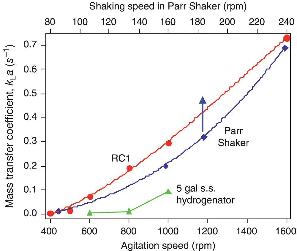
FIGURE 9.6 Hydrogen mass transfer coefficient kLa as a function of the agitation intensity for three types of hydrogenators: the 1 L Mettler Toledo's RC1 MP10 reactor (500 ml MeOH), a 5 gal stainless steel hydrogenator with mechanical agitation (2.5 gal MeOH) and the 250 ml Parr shaker (90 ml MeOH).
Taking advantage of its design precision, e.g. the reproducible agitation ramp from zero to the desired agitation rate in less than 0.2 seconds, we first used the 1 L Mettler Toledo's RC1 MP10 system to study the effect of the hydrogen pressure on kLa using methanol as the solvent. The results show that the kLa value is rather independent of the hydrogen pressure over the range of 15–100 psig. Given this observation, we simply choose any convenient hydrogen pressure in this pressure range for the kLa measurement.
To the best of our knowledge, mass transfer characteristics of the Parr Shaker system, traditionally and frequently employed for development of hydrogenation processes, have not been reported. Figure 9.6 shows that the Parr Shaker possesses surprisingly good mass transfer capability rivaling the best achievable in the RC1 system that is known for its good mass transfer capability. At the shaking frequency typically used for process development, the value of kLa is moderate, 0.1 s−1 at 130 rpm. Higher kLa values are achievable at higher shaking frequencies. Figure 9.7 shows several pressure curves measured in the Parr Shaker. Figure 9.6 also shows that the mass transfer capability of the specific 5 gal hydrogenator studied even at the highest allowable rpm (1000 rpm) is somewhat limited (kLa = 0.1 s−1).

FIGURE 9.7 Decay of pressure in the head space due to the non‐reactive hydrogen uptake by methanol (90 ml) in the Parr Shaker (250 ml), parametric in the shaking frequency.
The simple methodology is applicable to kLa measurement in large hydrogenators in manufacturing facilities. The mass transfer capability of a factory glass‐lined hydrogenator with a nominal 750 gal volume (900 gal actual, with a retreat blade impeller, one baffle, subsurface sparging) was characterized. The results revealed a limited gas–liquid mass transfer capability of this specific hydrogenator even with 100% agitation power. For instance, at a 460 gal fill and with the full agitation power, the kLa value is 0.035 s−1, a mass transfer coefficient equivalent to that in the RC1 reactor at 500 rpm only (Figure 9.6). The low mass transfer ability in this hydrogenator makes it not suitable for running fast hydrogenation reactions that require kLa > 0.035 s−1 at the existing configuration.
9.5 CHARACTERIZATION OF CATALYST REDUCTION PROCESS
For hydrogenation processes in a solvent with a solid supported metal catalyst, an important process involved is the reduction of the catalyst itself to its metallic state. For example, the Pd in the typical Pd/C catalysts is either in the form of palladium hydroxide or in the form of metallic palladium particles with its surface layers oxidized. Reduction of the surface Pd to its metallic state is necessary for the catalytic hydrogenation processes. While reduction of Pd/C catalysts used in the gas–solid reactions can be conveniently studied, to the best of our knowledge, the kinetics of catalyst reduction under the gas–liquid–solid slurry hydrogenation conditions has not been reported. How long does it take to reduce the catalyst under the slurry hydrogenation conditions? What does the kinetics look like? Is it instantaneous upon pressurization of the hydrogenator? How do the solvent, the additives, and the substrate influence the kinetics of the catalyst reduction? How do the transient properties of the catalyst during the catalyst reduction process influence reactivity and selectivity of the hydrogenation of the substrate? These questions remain unanswered due to a lack of research tools to characterize the kinetics of the catalyst reduction in situ under the slurry hydrogenation conditions. In this section, a simple procedure is described that allows one to measure the characteristics of the catalyst reduction process.
The procedure is an extension of the kLa measurement protocol described in Section 9.4. First, profile of the nonreactive uptake by the solvent is measured. Profile of the sum of the nonreactive and reactive hydrogen uptake due to the catalyst reduction is subsequently measured by repeating the same procedure (under the identical conditions) after addition of the heterogeneous catalysts to the solvent in the batch. The uptake profile due to the catalyst reduction can be extracted by taking the difference of the two uptake profiles.
The methodology is demonstrated in Figure 9.8 for measuring the reduction rate of a Pd/C catalyst in methanol at −10 oC. The hydrogen uptake curves at 40 psig H2 and at −10 °C upon agitation (1000 rpm) for MeOH (500 ml) only and for MeOH (500 ml) plus the 5%Pd/C catalyst (10 g) were measured consecutively, and the results are shown in Figure 9.8a. Because the two uptake curves were measured under the identical conditions except that one is with the Pd/C catalyst added, the nonreactive uptake curve can be directly subtracted from the sum curve to generate the uptake curve associated only with the Pd/C reduction. By subtracting the two curves in Figure 9.8a, the reduction profile of the Pd/C catalyst emerges and is shown in Figure 9.8b.

FIGURE 9.8 (a) Hydrogen uptake curves at 40 psig H2 and at −10 °C upon agitation (1000 rpm) for MeOH (500 ml) only and for MeOH (500 ml) plus 5%Pd/C (10 g, Type 21, JM), following the standard kLa measurement procedure described in Section 9.4. Apparatus: Mettler‐Toledo's RC1 with an MP10 reactor (b) Difference between the two uptake curves in (a), representing the reactive hydrogen uptake by the reduction of the Pd/C catalyst only. The dash line is a fit to a double exponential function Uptake = 2.55 − 1.65e−0.0177t − 1.34e−0.0864t.
A few properties of the reduction process become apparent from Figure 9.8b. The reduction is a relatively fast process – it is nearly completed in 2 minutes at 40 psig H2 and at −10 °C. The reduction kinetics exhibits two distinct regimes and can be fitted nearly perfectly by a double exponential function, i.e. Uptake = 2.55 − 1.65e−0.0177t − 1.34e−0.0864t. The fast rate process has a half‐life of ca. 8 seconds and is likely associated with the reduction of the outside layers of Pd catalyst particles, whereas the slower rate process has a half‐life of ca. 39 seconds and is likely associated with the reduction of the bulk of the Pd catalyst particles and with the formation of bulk palladium hydrides. Figure 9.8b also shows that the overall stoichiometry of the reactive hydrogen update for this catalyst is H/Pd = 1.3.
A closer look at the uptake profile in Figure 9.8b shows there is a short induction period (~4 seconds) in the catalyst reduction at −10 °C, i.e. there is no appreciable hydrogen uptake in the presence of 40 psig hydrogen for approximately 4 seconds. The induction period virtually disappears at 25 °C for the catalyst reduction. This temperature effect is more evident when the reduction profiles at the two temperatures are placed in the same graph in Figure 9.9. Interestingly, the kinetics in the fast rate regime at 25 °C is similar to that at −10 °C (similar slopes of hydrogen uptake at the fast rate regimes). The total reduction hydrogen uptake is at 25 °C that is however less, presumably due to lower equilibrium surface coverage of the hydrogen atoms on Pd and the bulk concentration of the Pd hydride at higher temperatures.

FIGURE 9.9 A comparison of the reduction kinetics of the 5%Pd/C catalyst (Type 21, JM) at −10 and 25 °C. The experimental conditions are identical to those described in Figure 9.8.
The methodology provides a convenient way to measure the catalyst reduction kinetics in solvents under the hydrogenation conditions except that the substrate is not present. In the presence of the substrate, the reactive hydrogen uptake would originate from the catalyst reduction and from the substrate hydrogenation. The methodology described here cannot deconvolute the rate of the catalyst reduction from the rate of the substrate hydrogenation. How the presence of the substrate effect the reduction kinetics of the heterogeneous catalysts remains unclear. One thing clear is that the kinetics of the catalyst reduction can be altered by the substrate in the hydrogenation reaction. Figure 9.10 shows the effect of the addition of ammonia to the methanol solvent on the catalyst reduction at −10 °C. In this experiment, a small amount of aqueous ammonia (0.78 mol) was added into methanol to a total volume of 500 ml, and the catalyst reduction kinetics was studied following the standard procedure. The two hydrogen uptake curves measured are displayed in Figure 9.10a. The catalyst reduction kinetic profile derived from Figure 9.10a is plotted in Figure 9.10b along with the kinetic profile of the catalyst reduction in methanol alone as a reference.

FIGURE 9.10 (a) Hydrogen uptake curves at 40 psig H2, −10 °C, 1000 rpm for MeOH + NH3(aq.) (500 ml) and for MeOH + NH3(aq.) (500 ml) plus 5%Pd/C (10 g, Type 21, JM), following the standard kLa measurement procedure described in Section 9.4. (b) Kinetics of the Pd/C catalyst reduction in MeOH + NH3(aq.), in comparison with the kinetics in MeOH only.
Source: Reproduced from Figure 9.8b.
The most striking feature of the reduction kinetics in the presence of ammonia is that there is a significant induction period, approximately 60 seconds, much longer than the 4 seconds induction period in MeOH without the ammonia addition. Over this long induction period, there is virtually no hydrogen uptake. At the end of the induction period, the rate of the Pd catalyst reduction accelerates. This induction period may result from strong chemisorption of ammonia on the surface of the Pd catalyst, inhibiting dissociative chemisorption of dihydrogen on Pd. Adsorption of a small amount of hydrogen on the catalyst surface through competitive adsorption process reduces a small fraction of the surface Pd, which conversely facilitates dissociative chemisorption of additional hydrogen, leading to the rate acceleration. The maximum rate of the reduction, however, is slower than that in the absence of ammonia (Figure 9.10b). The long induction period is attributed to the presence of ammonia in the hydrogenation batch. Independent experiments showed that water as a result of the aqueous ammonia addition does not alter the catalyst reduction. Overall, the addition of ammonia extended the catalyst reduction time scale from ca. 2 to 7 minutes, suggesting that additives used in hydrogenation reactions and the substrate itself can influence the catalyst reduction kinetics.
9.6 BASIC SCALE‐UP STRATEGY FOR HYDROGENATION PROCESSES
When a hydrogenation process is translated from the laboratory to the plant, chemists and chemical engineers sometimes encounter scale‐up issues such as problems with reactivity and/or selectivity. Often the scale‐up issues can be traced to a lack of characterization or understanding of the various rate processes and an ensemble of key factors that affect the reproducibility and robustness of the hydrogenation process. A successful scale‐up necessitates that these factors be identified, measured, and controlled. This section discusses some of the fundamental factors that need to be considered for a successful scale‐up. A basic strategy for scaling up hydrogenation processes is described in terms of several quantitative criteria.
The most basic requirement for a successful scale‐up is for the chemists and engineers to have at the laboratory development stage a true understanding of reaction kinetics that is intrinsic to the catalytic system, i.e. one that is not masked by H2 mass transfer limitations but is obtained under well‐defined conditions, in particular, with a known [H2]lab. The best strategy to achieve this is to characterize the mass transfer capability of the hydrogenation reactor and use the 10% rule of thumb (as described by Eq. (9.7)) in the laboratory developmental work so that the condition
is also satisfied at all times. Availability of the intrinsic kinetic information allows one to make an intelligent choice of reactors and reaction conditions for reproducible and robust scale‐ups.
The hydrogen mass transfer coefficient kLa of the hydrogenation reactor is one of the primary factors to consider in scale‐up because it can have direct impact on kinetics, process safety, and selectivity. It is not uncommon, however, to find hydrogenation process descriptions specifying only the gas‐phase H2 pressure and agitation speed without specifying the requirement for the mass transfer coefficient kLa of the hydrogenator. To scale up a process in this manner subjects the process to the risk of running under ill‐defined conditions, i.e. undefined [H2] that is disengaged from the gas‐phase hydrogen pressure. To reproduce in the plant runs the rate and selectivity observed in the laboratory, it is important that [H2] in the plant runs be the same as the [H2] used in the laboratory development work, i.e.
Using the same pressure as that employed in the laboratory development without specifying kLa does not necessarily guarantee that this condition (Eq. 9.11) is satisfied.
When one runs the plant process far from the hydrogen mass transfer limited situations, the hydrogen concentration [H2] is known and constant (as long as the gas‐phase pressure remains unchanged) over the entire course of reaction. This is particularly important for hydrogenation reactions with [H2]‐dependent selectivity. If this type of reactions is operated under hydrogen diffusion limitations, [H2] deviates from [H2]sat and becomes disengaged from the gas‐phase hydrogen pressure. The solution goes from hydrogen starved at the beginning stage of reaction when the intrinsic hydrogenation rate is fast to hydrogen saturated at the later stage of the reaction when the intrinsic hydrogenation slows down due to depletion of the starting material. The selectivity would vary throughout the course of the reaction as a result. In addition, rate of a process running under hydrogen mass transfer control is sensitive to slight changes in reaction conditions. For example, the rate can change significantly with changes in rpm due to the commonly observed exponential dependence of kLa on the agitation rate. The rate would not be affected by changes in the agitation rate, however, for processes running away from hydrogen mass transfer limitations.
To satisfy the scale‐up requirement described by Eq. (9.11), the 10% rule of thumb (Eq. 9.7) provides a good general guideline for matching the mass transfer capability of the hydrogenation reactor to the kinetics of a process. Given a process with known intrinsic kinetics, the chosen reactor for scale‐up needs to have a minimum mass transfer coefficient of
In addition, heat transfer issue also needs to be considered for safe operations in scale‐up. The following criteria need to be met:
where ![]() is the maximum heat removal capability of the reactor and
is the maximum heat removal capability of the reactor and ![]() is the heat of hydrogenation per mole of H2 reacted.
is the heat of hydrogenation per mole of H2 reacted.
The inherent reaction kinetics and the criteria described by Eqs. (9.12) and (9.13) form some of the basic requirements that need to be considered for successful scale‐ups of hydrogenation processes.
9.7 SUMMARY
Dissolution of H2 into the liquid phase is the first rate process along the H2 pathway in catalytic hydrogenation reactions. The dissolution kinetics can play a key role in the kinetics and selectivity of catalytic reactions and the outcome of process scale‐up. At a given gas‐phase H2 pressure, while thermodynamics determines the solubility [H2]sat, it is kinetics that determines the actual solution H2 concentration [H2] or the “effective hydrogen pressure” that the catalyst experiences during hydrogenation reactions. Depending upon the relative magnitude of the rate of H2 mass transfer across the gas–liquid interface vs. the rate of the reactive removal of the dissolved H2 from the liquid phase by hydrogenation, [H2] may vary greatly from saturation to nearly zero, even at a constant pressure in the gas phase. The influence of mass transfer on [H2] exerts a direct impact not only on rate but also on selectivity for reactions whose selectivity depends on [H2]. It is also often the fundamental cause of irreproducibility in rate and selectivity observed from reactor to reactor (e.g. when scaling up a lab process in the manufacturing facility) when the same reaction is carried out under seemingly identical conditions. This is because different mass transfer capabilities of reactors of different types and scales can lead to different “effective pressures” even at a constant gas‐phase pressure.
A catalytic hydrogenation process should be carried out under conditions where the intrinsic hydrogenation rate is at least 10 times lower than the maximum rate of H2 mass transfer across the gas–liquid interface. This ensures that the observed kinetics and catalytic behaviors are not masked by the mass transfer limitations but are intrinsic to the catalytic system under well‐defined conditions. This requirement may serve as a general guideline for designing scalable processes, since as long as the 10% rule of thumb is satisfied, the hydrogenation process is “portable,” i.e. the same kinetics and catalytic behavior will be reproduced from reactor to reactor at any scale. Strategy for a successful scale‐up of hydrogenation processes is formulated in terms of a set of quantitative criteria.
The process of reduction of a Pd/C catalyst under the hydrogenation conditions is characterized using a novel methodology. The results show that the catalyst reduction process can have an induction period, is relatively fast (on the order of <5 minutes) under typical hydrogenation conditions, and can be significantly influenced by the nature of the additives or the hydrogenation substrates.
ACKNOWLEDGMENTS
We thank Prof. Donna Blackmond for helpful discussions and Andy Newell, Charlie Bazaral, and Steve Conway for assistance in experiments.
REFERENCES
- 1. (a) Rylander, P. (1990). Hydrogenation Methods. London: Academic Press.
(b) Rylander, P. (1979). Catalytic Hydrogenation in Organic Synthesis. New York: Academic Press. - 2. Augustine, R.L. (1995). Heterogeneous Catalysis for the Synthetic Organic Chemists. New York: CRC Press.
- 3. Knowles, W.S. (2002). Asymmetric hydrogenations. Angewandte Chemie International Edition 41: 1998.
- 4. Knowles, W.S. and Noyori, R. (2007). Pioneering perspectives on asymmetric hydrogenation. Accounts of Chemical Research 40: 1238.
- 5. Noyori, R. (2002). Asymmetric catalysis: science and opportunities. Angewandte Chemie International Edition 41: 2008.
- 6. Noyori, R. (1994). Asymmetric Catalysis in Organic Synthesis. New York: Wiley, and references therein.
- 7. Krische, M.J. and Sun, Y.K. (2007). Hydrogenation and transfer hydrogenation. Accounts of Chemical Research 40: 1237–1237.
- 8. See for example(a)Sun, Y.K., Landau, R.N., Wang, J. et al. (1996). A re‐examination of pressure effects on enantioselectivity in asymmetric catalytic hydrogenation. Journal of the American Chemical Society 118: 1348.(b) Sun, Y.K., Wang, J., Landau, R.N. et al. (1996). Asymmetric hydrogenation of ethyl pyruvate: diffusion effects on enantioselectivity. Journal of Catalysis 161: 759.
- 9. (a) Ramachandran, P.A. and Chaudhari, R.V. (1983). Three‐Phase Catalytic Reactors, Topics in Chemical Engineering, vol. 2, Chap. 9. New York: Gordon and Breach Science Publishers.(b) Beenackers, A.A.C.M. and Van Swaaij, W.P.M. (1993). Mass transfer in gas‐liquid slurry reactors. Chemical Engineering Science 48: 3109.(c) Hines, A.L. and Maddox, R.N. (1985). Mass Transfer: Fundamentals and Applications. Englewood Cliffs, NJ: Prentice‐Hall.
- 10. (a) Landis, C.R. and Halpern, J. (1987). Asymmetric hydrogenation of methyl (Z)‐.alpha.‐acetamidocinnamate catalyzed by [1,2‐bis((phenyl‐o‐anisoyl)phosphino)ethane]rhodium(I): kinetics, mechanism and origin of enantioselection. Journal of the American Chemical Society 109: 1746.(b) Sun, Y.K., Landau, R.N., Wang, J. et al. (1996). A reexamination of pressure effects on enantioselectivity in asymmetric catalytic‐hydrogenation. Journal of the American Chemical Society 118: 1348.
- 11. Sun, Y.K., LeBlond, C., Wang, J. et al. (1995). Observation of a [RuCl2((S)-(-)-tol-binap)]2 · N(C2H5)3-catalyzed Isomerization‐Hydrogenation Network. Journal of the American Chemical Society 117: 12647.
- 12. Wang, J., Sun, Y.K., LeBlond, C. et al. (1996). Asymmetric hydrogenation of ethyl pyruvate: relationship between conversion and enantioselectivity. Journal of Catalysis 161: 752.
- 13. Sun, Y.K., Wang, J., LeBlond, C. et al. (1997). Kinetic influences on enantioselectivity in asymmetric catalytic hydrogenation. Journal of Organometallic Chemistry 581: 65.
- 14. (a) Matsumara, M., Masunaga, H., and Kobayashi, J. (1979). Gas absorption in an aerated stirred tank at high power input. Journal of Fermentation Technology 57: 107.
(b) Deimling, A., Karandikar, B.M., Shah, Y.T., and Carr, N.L. (1984). Solubility and mass transfer of CO and H2 in Fischer‐Tropsch liquids and slurries. Chemical Engineering Journal 29: 140.
(c) Blaser, H.U., Garland, M., and Jallet, H.P. (1993). Enantioselective hydrogenation of ethyl pyruvate: kinetic modeling of the modification of Pt catalysts by cinchona alkaloids. Journal of Catalysis 144: 569.