
46
KILO LAB AND PILOT PLANT MANUFACTURING
Matthew Casey1, Jason Hamm, Melanie Miller, Tom Ramsey2, Richard Schild3, Andrew Stewart4, and Jean Tom
Product Development, Bristol‐Myers Squibb, New Brunswick, NJ, USA
46.1 INTRODUCTION
The pharmaceutical industry has traditionally divided its scientific efforts to bring a drug to market into three stages: drug discovery, process development, and manufacturing. Process development is the link between the worlds of the laboratory and the commercial manufacturing plant. To accomplish this mission, chemical engineers in process development groups must be knowledgeable and capable in both arenas – laboratory experimentation and plant scale‐up.
The two primary deliverables from the development efforts are the supply of drug substance or active pharmaceutical ingredient (API) and the process knowledge generated. The API fuels several key activities including clinical studies, toxicological studies, and formulation development. The process knowledge forms the basis of a sustainable commercial manufacturing process. Figure 46.1 shows the work process and the organizational structure metaphorically represented as a bridge. In this case the bridge is process development physically linking drug discovery to manufacturing. At the foundation of the bridge is knowledge, both process knowledge and regulatory knowledge as required by agencies such as the FDA. Also shown are several steps of the bridge representing the progression and deliverables of the development process (toxicological study supplies, clinical supplies, and process optimization). Two important tools available to process development groups to carry out their mission are kilo labs and pilot plants.
FIGURE 46.1 Process development links drug discovery and manufacturing.
There can be significant differences across the pharmaceutical industry in what is meant by the terms kilo lab and pilot plant. Some companies differentiate kilo labs from pilot plants by equipment size and may refer to kilo labs as glass plants because of the extensive use of glass equipment typically found in these facilities. Other companies designate all of their scale‐up facilities as pilot plants, making no distinction between equipment size and scale of the facility.
Kilo labs are typically utilized for the first scale‐up to produce sufficient quantities for initial drug testing, i.e. toxicological studies or phase I clinical trials. Typical chemistry used is less developed than at later stages and is often a modification of the longer, less efficient discovery chemistry route. Kilo labs are designed to yield quantities ranging from 100 g to under 10 kg of materials with typical batch sizes of 2–3 kg (hence the historic reference to kilo lab). Reactor sizes usually range from 20 to 100 L where the material of construction is often glass. The kilo lab represents the first step out of the lab, and the equipment design is typically closer to a laboratory (larger glassware) than a manufacturing plant (industrial equipment).
Kilo labs typically have a high degree of flexibility to accommodate a range of complex chemistries. Portable equipment setups are configured to meet specific process needs, and disposable components may be used to control product cross contamination or decrease turnaround time for process areas. Ideally, the kilo lab infrastructure is sufficient to support “mini‐piloting” or scale‐down studies to explore process changes prior to scale‐up in the pilot plant. Equipment similar in design to the pilot plant equipment (e.g. filter dryers) is often available to accelerate identification of scalability issues. While many kilo labs are likely manually operated, kilo labs with robust data collection systems can provide key process information to further development, making the kilo lab more than a place to generate kilogram deliveries.
Pilot plants in contrast are typically larger than kilo labs with designs that more closely resemble the commercial manufacturing plant. Supplies generated in pilot plants often support phase II and later clinical or chronic toxicology studies. At the pilot plant stage, demonstration of potential commercial routes and generation of process knowledge through data collection can be key objectives. Though design standards and size differ among companies, pilot plant reactors typically range in scale from 200 to 4000 L.
The pilot plant, like the kilo lab, must operate with a degree of flexibility and absorb process and schedule uncertainties. However, pilot plants typically have more substantial infrastructure and regulatory requirements for quality, safety, and environmental concerns. Pilot plant operations often run one to three shifts per day and five to seven days per week as needed to manage process chemistry requirements and changes in campaign objectives (e.g. timing or quantity). Portable equipment will also supplement the fixed equipment trains to support process‐specific needs. Examples of such equipment include portable tanks, filters, pumps, wet mills, chromatography equipment (i.e. columns, pumping skids), and process analytical technology (PAT) instruments (Figure 46.2).
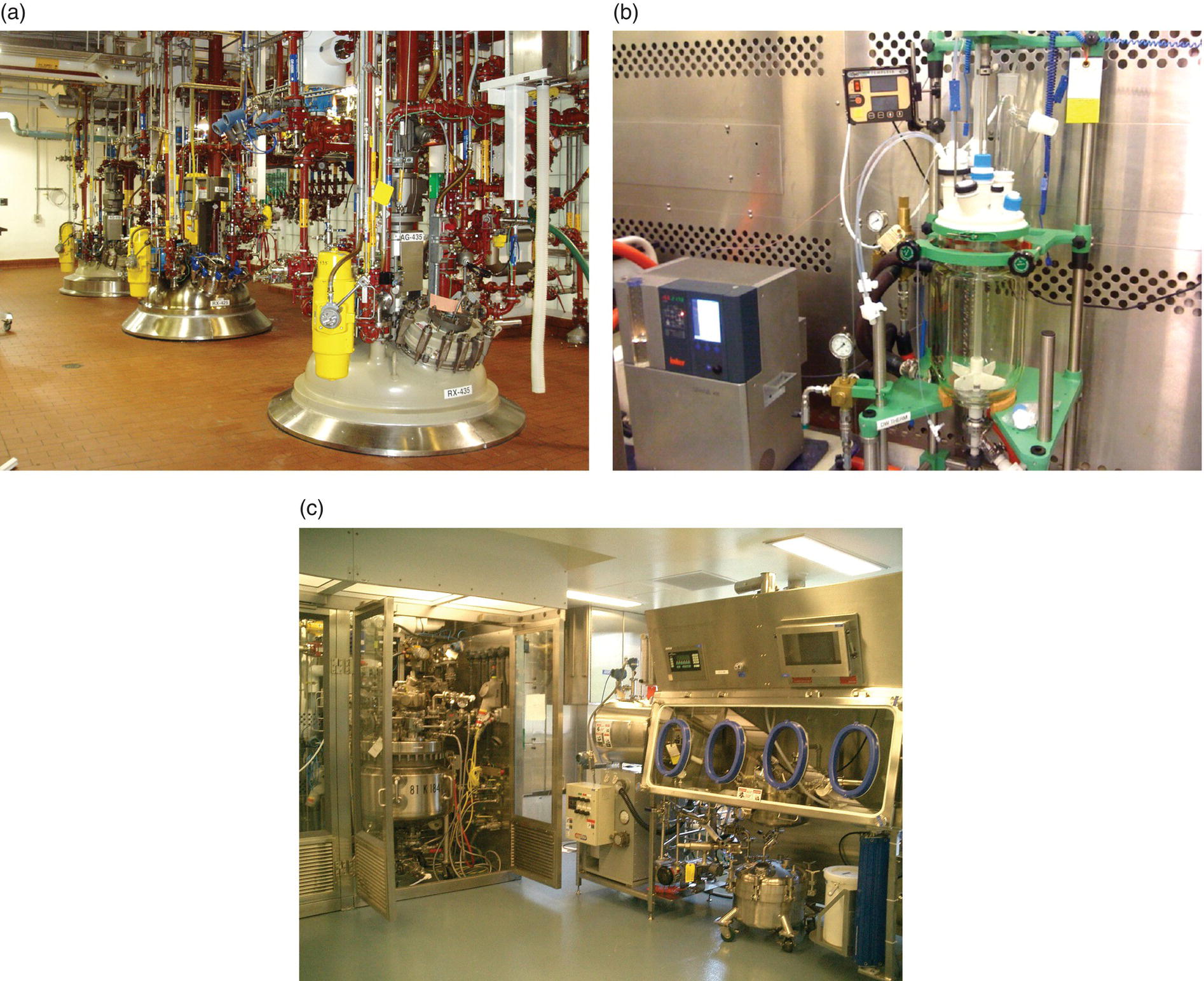
FIGURE 46.2 Examples of pilot plants and kilo labs. (a) Pilot plant process area showing three reactors (1000–4000 L) and associated overhead piping. (b) A typical kilo lab with small glass reactor (10 L). (c) Kilo lab process area showing larger reactors (left) in downflow booth and Nutsche filter and tray dryer inside isolator (right) with filtrate receiver underneath.
One element that differentiates facilities in the pharmaceutical industry from those in the chemical process industry is the requirement to follow current good manufacturing practices or cGMPs when preparing clinical supplies. Good manufacturing practices are governed by regulatory health authorities such as Food and Drug Administration (FDA) and European Medicines Agency (EMA) and are defined within six quality systems: quality, production, facilities and equipment, laboratory controls, materials, and packaging and labeling. More information is provided in Section 46.3.
Figure 46.3 shows a graphical representation that matches the facilities and scale to the phase of clinical development. Many pharmaceutical companies have laboratories, kilo labs, and pilot plant facilities available as an internal capability. Other companies leverage vendor facilities to supplement or replace internal capabilities at each scale of development. The individual company strategy may vary to outsource several of the early steps in the synthesis to vendors while executing only the last several steps internally or outsourcing of full synthetic route depending upon business and regulatory drivers. Each company develops its strategy through assessment of the cost and benefit of maintaining internal capabilities and to what scale and capacity.

FIGURE 46.3 Progression of scale‐up of chemical processes.
The basis of an operating philosophy for a kilo lab or pilot plant is safe production of high quality product while meeting all necessary regulatory requirements. Process safety is constant throughout process development and a primary consideration for process design and execution decisions. Appropriate systems and procedures regarding plant operation and material flow following cGMP provide the basis for the operating philosophy to support generation of high quality supplies for clinical studies. Processing activities in the facility are the source of process data and knowledge, and the plant's capability to generate such information is a key part of the operating philosophy for the facility. Business objectives for cost‐ and time‐efficient operation of the facilities must also be met. As a result, there is a complex balance of timely and cost‐effective manufacture of intermediates and APIs while obtaining sufficient processing experience to advance knowledge and development of the process.
46.1.1 Operating Staff
The personnel overseeing and working in the facility are key components of a kilo lab or pilot plant facility's ability to operate in a manner demanded by safety and regulatory requirements. They play a critical role in the workflows to operate the facility as well as compliance with the regulatory drivers. The size and makeup of the facility staff will also determine how the facility is run.
In the kilo lab, operating staff may include chemists or chemical engineers. The kilo lab scientist supplements the process development scientists and brings an understanding of scalability issues and process safety risks as well as strong process troubleshooting skills. In some kilo lab facilities, a lab manager may oversee the facility and its maintenance while coordinating the project scientists who execute process activities in the facility.
In a pilot plant, many of the named roles are similar to those in a manufacturing plant: plant manager, process engineer, chemical operator, and facility support staff, such as maintenance, process automation, and supply chain. The process safety group can be part of the facility staff, but in some companies it is part of the process development groups. Analytical support for in‐process assays and quality assurance groups are important links to ensuring overall operation of the pilot plant, but typically are not part of the plant operations staff. The number of staff in each role is determined in large part by the planned capacity utilization of the pilot plant, the size and complexity of the infrastructure, and the operational cost base. For the plant manager, the process engineer, and the chemical operator, there are significant differences between the skill sets required between R&D and manufacturing:
- The plant manager of a pilot plant is at the intersection of process development activities, campaign execution, and facility support with a broad range of responsibilities from resource management, safety, cGMP, and environmental compliance to readiness for regulatory inspection. It is essential that the manager have sufficient knowledge to understand the various customer needs and manage the dynamic environment of new process implementations.
- The process engineer serves an important function in transferring/implementing the defined process into the facility. In partnership with the process development team, the process engineer identifies the process fit, drives equipment decisions, and supports modeling decisions to help define equipment operating parameters. Examples include agitation rates for solids suspension, reactor heat and mass transfer determinations, distillation modeling, and drying times. During execution, the process engineer may work as a team with the process supervisor and chemical operator to ensure successful implementation and proper mitigation of risks. Upon completion of a batch and/or campaign, the process engineer also supports data analysis activities to capture key learnings and implement improvements for future campaigns. In addition to process data, the process engineer will summarize all material accountability and yield data with the complete data package. A solid foundation in chemical engineering fundamentals, good understanding of equipment design and operations, and the ability to communicate to individuals of diverse backgrounds and educational levels is important.
- The chemical operator in manufacturing is involved in the execution of fully developed chemical processes to prepare marketed products; process robustness is expected, and the operator is trained and qualified to execute the process. By contrast, the chemical operator in an R&D pilot plant is involved in the execution of processes as they are developed, whereas process variability is routine. Each new campaign is a new process introduction. The R&D operator generally trains and is qualified on process equipment, process troubleshooting, and unit operations independent of a specific process.
46.2 KILO LAB AND PILOT PLANT FACILITY DESIGN AND UNIT OPERATIONS
For both the kilo lab and the pilot plant, the key objective is to provide for as much flexibility and agility as possible to manage a dynamic portfolio of potential products while meeting environmental, health, and safety (EHS), product quality, and business requirements. Though they may appear separate, a well‐designed facility acknowledges the benefits of integrated quality and safety systems. Below are several characteristics common to R&D pilot plant and kilo lab designs:
- The materials of construction of all equipment and associated piping systems provide corrosion resistance to a range of process conditions. This reduces concerns of material incompatibility between equipment components and process streams and allows a wide variety of chemistries to be run. The most common material choices are glass or glass‐lined equipment, Teflon®, stainless steel, and high‐end corrosion‐resistant alloys such as Hastelloy®.
- The equipment is designed to cover broad temperature and pressure ranges to support safe execution of all typical unit operations.
- Pilot plant facilities should incorporate a blend of fixed and portable equipment in a complementary fashion to increase the diversity of available equipment configurations while managing the amount of time required to change over from one process to the next. The equipment can be set up relatively fast and inexpensively through the use of standard equipment designs and utilization of quick connect or single‐use hoses.
- The equipment and facility should be designed for cleanability and to mitigate the risk of cross contamination between products. Kilo labs and pilot plants are multiproduct facilities that often execute multiple processes simultaneously. It is critical to keep individual process areas clean and to design building air flows to minimize the chance of product contamination between process areas.
- The building and process automation systems enable improved operability of equipment and the capture of data to further the understanding of the process and to satisfy regulatory requirements. Although many facilities have some capacity to capture and retain process data, the outputs of this data are very different. Process data may be captured locally within batch documentation or via a programmable logic controller (PLC). More recently designed facilities could have distributed control systems (DCS) that have the availability to retain data in process data historians on local, enterprise, or cloud‐based servers. Scientists and process engineers will benefit from advanced process control systems that interface with common engineering analysis/modeling tools to summarize and analyze data in a semi‐automated method.
- The facility and equipment should include industrial hygiene engineering controls (i.e. barrier technology) as the primary defense against operator exposure to chemicals, drug candidates, and their intermediates. Many advances have been made with both fixed and disposable isolator technology (see Section 46.2.5) that should be considered and implemented to improve the containment/exposure design of the facility. Personal protective equipment (PPE), although a required safety measure, should not be used as the primary control to mitigate the risk of worker exposure.
- The facility should be able to execute products at both early and late stages of the development cycle. A kilo lab may be called upon to execute a low volume product at a late stage in development, while a pilot plant may be the right venue for early stage products with high volume requirements.
- The facility must support the ability to safely produce clinical material being consumed by humans with the proper employment of cGMP for the stage of development. Adherence of key aspects of the facility to cGMP needs to be considered. These include raw material and personnel flow; heating/ventilation/air conditioning (HVAC) design and air balance; maintainability; and cleanability.
- The facility must meet all relevant safety codes as required by regional, federal, and state regulations.
Each chemical process can be broken down into a series of unit operations and may be conducted in a batch, semi‐batch, or continuous mode of operation. The most common unit operations for a typical process are described below:
- Equipment preparation: A critical aspect of all process implementation is the proper preparation of the equipment from both safety and quality perspectives. When the process is ready to start, all equipment must undergo an integrity check to ensure no leaks are present and residual oxygen has been removed. This preparation is best completed by performing a pressure and/or vacuum leak check and inertion cycles with nitrogen. Once the integrity of the equipment is confirmed, preprocess rinses, with supplemental in‐process control samples, may be required to ensure the equipment is in the proper state (i.e. free of water) prior to proceeding with the process.
- Charging components: The starting component is typically a solid and is charged to the reactor through an open system, such as scooping material in through the reactor manway or through a closed system. Closed charging systems protect the worker and the material from contamination and include split butterfly valves, powder transfer systems, and glove box technology. Liquids are charged through reactor nozzles by pump, vacuum, or pressure transfers.
- Reaction: The reaction is where the molecule is being synthesized within each batch step progressing to the preparation of the API. It normally involves heating, cooling, controlled addition rates of reagents, and agitation. Thermal chemistry studies and energy balances should be completed prior to execution to ensure safe processing.
- Workup: A workup is typically completed post‐reaction and can be composed of multiple unit operations including reaction quench, extractions, adsorption (color or impurity removal), polish filtrations, and distillations.
- Crystallization: Following the workup, the crystallization is performed to precipitate the solid product from the solution by modifying the solubility of the solution via cooling, antisolvent addition, volume reduction, and/or seeding. The crystallization is a critical aspect of the process typically requiring thorough understanding of the crystallization process and product solubility to control impurity purging, desired material form/morphology, and/or powder properties. The crystallization is one of the most complex and important steps in controlling product quality and downstream processing characteristics.
- Filtration: The crystallized solids are separated from the carrying liquids, also known as mother liquors, using filtration equipment. The filtered cake is washed with appropriate solvent(s) to facilitate impurity and residual solvent removal. Filter dryers, pressure filters (Nutsche or plate), and centrifuges are common filtration devices found in pilot plants and kilo labs.
- Drying: The solids are dried typically using heat and vacuum to remove residual solvent. The dryer may be controlled to produce the desired polymorph or form of the product. Commonly found contact dryers include tray dryers, agitated dryers, and tumble dryers (see Section 46.2.4.3).
- Dry powder finishing: Milling or micronization (for particle size reduction) as needed based on the powder property attributes of the API and the requirements for successful formulation into the drug product.
46.2.1 Kilo Lab Design
Kilo labs are typically installed within a laboratory building and are generally not found as stand‐alone facilities. Kilo labs in close proximity to process development and analytical laboratories encourage interactions between scientists, allowing for greater synergy between laboratory and scale‐up operations. Kilo lab workflow as an extension of laboratory practices can improve efficiency and decrease the time needed to execute a process. However, the shared infrastructure can present challenges to the control of material and personnel workflow. Requirements for controlled personnel access and separate physical areas to manage segregated storage of raw materials and material subdivision apart from laboratory operations will increase the complexity of the area management.
Laboratory buildings typically employ central corridors for transport of materials and personnel. Air locks are often employed as physical separation of the kilo lab process areas from the rest of the building and reduce unnecessary personnel flow into the areas. The air locks also help to maintain proper air balance and pressure differentiation between the process areas and the corridor (see Section 46.2.3.1).
Most of the processing for a single intermediate or API is performed in one room or area. This includes all the material charging, reactions, workup, isolation, and filtration. The most common exceptions are drying and milling, which may be performed in separate locations specifically designed for handling dry powders.
Potential for cross contamination between products should be considered at each phase of facility and process design. Contamination occurs primarily through airborne particulates and/or insufficient cleaning of product contact surfaces. Many approaches designed to minimize contamination also have benefit in protecting the kilo lab scientist from exposure to the compound. Downflow booths, fume hoods, barrier technology, and other engineering controls may be used to achieve closed processing are good examples (see Section 46.2.5). Placement of reactor systems into down flow booths or fume hoods, as shown in Figure 46.4, can increase process segregation for safety and quality. The same approach can be employed to segregate isolation and drying equipment. Where kilo labs are an extension of laboratory operations, specific laboratories can be designated for preparation of supplies destined for clinical use to further segregate process operations.
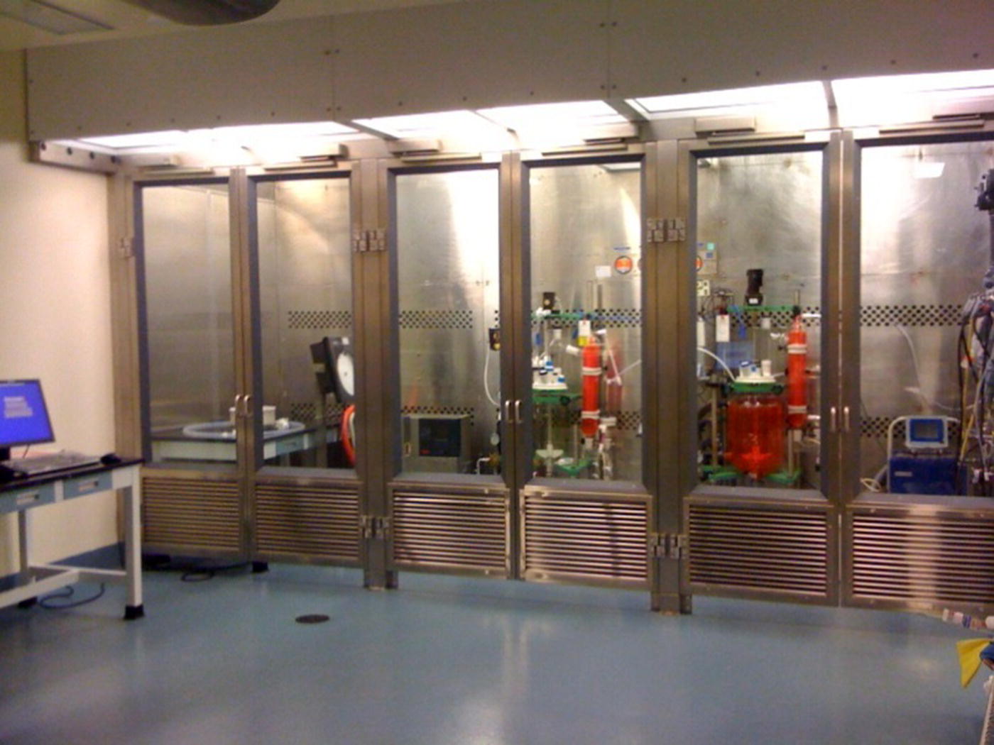
FIGURE 46.4 Typical kilo lab reactor shown in a downflow booth.
Equipment cleanability should be a consideration in the initial design of the equipment as well as in the design of the process equipment configuration for a specific product. Cleaning procedures should be developed to address a wide range of chemistries and process conditions, recognizing that little is known about the cleanability of the product at the early stages of development.
46.2.2 Pilot Plant Design
Unlike kilo labs, pilot plants are commonly designed as stand‐alone facilities. As the scale of the equipment increases, the set of equipment, often called the equipment train, designed to work together for producing a single intermediate or product will expand into multiple rooms. Since the 1990s, it has been common for new pilot plants to be constructed with a “gravity” design where the process will flow from upper floors to lower floors in the direction of gravity (Figure 46.5). In such a design, smaller equipment is typically located in the upper floors, and the larger vessels and filtration and drying equipment are located in the lower floors.

FIGURE 46.5 Schematic of gravity feed flow in a pilot plant facility.
Another design aspect is the use of closed space for a single train of equipment vs. an open floor space without walls or physical barriers between multiple equipment trains. The latter is common to designs of commercial pilot plant facilities where product segregation is supported by procedural controls rather than physical separation between the individual equipment trains for each product.
In stand‐alone pilot plants, loading dock areas, proximity of elevators, corridor layout, storage space, air locks, utilities, and processing areas can be addressed in a complimentary design. Material flow, personnel flow, and HVAC design can be engineered soundly with good anticipation of the end user's needs. Dryer discharge areas and milling areas may employ temperature and humidity monitoring and/or control. Like kilo labs, pressure differentials are utilized to mitigate risk of cross contamination from one processing area to another.
Pilot plants utilize a vast array of different surface finishes designed to promote compliance with cGMP requirements and a cost‐effective building maintenance life cycle. There is substantial emphasis on corrosion‐resistant finishes in wet chemistry areas where surfaces are subject to heavy traffic and potential chemical spills. Isolation and drying areas are designed with less concern about corrosive chemical exposure and greater emphasis on finishes that are easy to clean, including floor, ceiling, and wall surface areas.
A critical aspect of chemical processing is to control and mitigate the risk of operator exposure to solvents, reagents, and active ingredients with the use of engineering containment technologies. The scale and size of the equipment in a kilo lab scale may allow for extended use of isolator technology; however larger‐scale pilot plant facilities require more use of unit operation‐based containment technology. Areas and/or unit operations where materials are introduced to or exiting from the process train require the highest level of engineering controls to prevent operator exposure. Material charges to the equipment may be controlled using a single‐use isolator technology or a contained charging area to prevent facility contamination. Sampling of potent or hazardous compounds may include an isolated sample location or local equipment isolator. Discharges of both waste and product streams may be completed in isolated areas or utilizing downflow booths and disposable isolator technology. In addition to the engineering controls above, PPE such as gowning, supplied/filter air, and safety glasses/shields are typically utilized to prevent operator exposure should engineering controls fail.
Emissions control is an area of emphasis in pilot plant design. While kilo lab facilities can control the small amounts of process emissions through standard ventilation systems, pilot plants typically employ additional emission control technologies to minimize emissions to the atmosphere and ensure compliance with regulatory permits. Technologies used include condensers, thermal oxidizers, carbon absorption, gas scrubbers, and cryogenic condensers. It is common to employ primary and secondary control systems in series to minimize the impact of system failure. Regulations governing the reporting and controlling of process emissions vary by country or region.
Pilot plants following a standard design may not be suitable to run all types of chemistry. Safe execution of some chemical processes requires special facility design features that are not generally part of a standard design. Considerations include electrical classification, fire suppression systems, and wall construction (fire rated, damage limiting, blast resistant). Once the type of chemistry and list of chemicals is identified for a new facility or facility renovation, a full code review can be performed by the project architects and engineers to identify specific design requirements and/or gaps against the existing design. Electrical classifications or ratings determine the list and quantity of chemicals (flammable liquids and dry powders) that a facility can safely process within that design. The electrical rating influences the design of all electrical systems and components within the facility. Some chemistries, such as hydrogenation reactions or those involving pyrophoric materials, generally require specially designed areas or dedicated facilities to better mitigate the process safety risks.
46.2.3 Utility Systems
Utility systems generally fall into two groups: building systems and process support systems. Building utilities include electrical systems, potable water systems, utility steam/condensate systems, compressed air systems, fuel oil/natural gas systems, and control systems for process emissions (e.g. thermal oxidizer). Building utility systems do not come into direct contact with the product and generally do not impact its quality. Process support utilities include process gases (e.g. nitrogen, hydrogen), process solvents, process water, and temperature control fluids (e.g. glycol, thermal oils). These utilities influence the process environment through either direct process contact or their effect on process conditions. The impact of the utility on the product quality and the ability to meet cGMP production requirements determines the commissioning, qualification, and life cycle management for the system. Information on commissioning and qualification of equipment and systems is provided in Section 46.2.7.
In a chemical processing facility, process safety and environmental systems may have a critical impact on operations and employee safety, yet do not directly impact the quality of the product. The impact of system failure against EHS criteria should be a factor in the design and maintenance of the system.
The centralization or decentralization of utility systems has significant impact on cGMP operations as well as business economics. Centralization can be more cost effective and improve the maintainability of the equipment [1]. Some utilities (e.g. steam) are typically distributed to the pilot plants and kilo labs from a central source on the manufacturing site. Kilo labs may share building systems and some process support systems when situated in multipurpose buildings. However, some process utilities should be dedicated to the kilo lab area to mitigate the risk of system disruption due to general use or to segregate cGMP‐controlled systems (e.g. temperature control system, process nitrogen, vacuum). Both building and process support utilities are typically dedicated to a single pilot plant or group of pilot plants. Backup power systems or uninterrupted power supply to support key parts of the facility, such as a designated equipment train or utility, is another design feature that mitigates the risks posed by hazardous chemistry during power disruptions in the building or manufacturing site. Some utilities with an important role in the safe execution of chemical processes while meeting cGMP production requirements are HVAC, process nitrogen, process water, and temperature control systems.
46.2.3.1 Heating/Ventilation/Air Conditioning (HVAC)
The HVAC system includes equipment for the control of air pressure, air flow, particulates, humidity, and temperature. Proper design prevents the spread of contamination throughout a facility, which in turn provides a layer of protection to the worker from airborne compound exposure as well as protection of the product from airborne contamination of other products (cross contamination). The location of the facility and cGMP requirements are important considerations in determination of the needed HVAC capacity and control strategies. Air change requirements are typically 10–15 air changes per hour, requiring large air movement equipment (air handlers and exhaust fans). Considerations for design include the requirements for air balancing within and between manufacturing spaces, directional airflow, environmental control in process areas, and the potential for compound exposure to the environment. In general, the process area will have a negative pressure differential relative to the air lock, the air lock is typically positive relative to both the process area and the corridor, and the corridor is a relatively neutral area (Figure 46.6). Air locks may also be designed to be negative relative to the corridor depending on the room function and company design practices.
FIGURE 46.6 Example of design pressure in a pilot plant facility.
46.2.3.2 Process Water
The design of the process water system is driven by the quality requirements for the water produced, which are based on its intended use. Several factors influence those requirements including where the water is used in the synthesis (intermediate or API, early or late) and any microbial specifications for the API (sterile or low endotoxin). Water quality standards for pharmaceutical processing range from potable water, to endotoxin reduced, to water for injection (sterile API). There are several guidelines available to guide design of pharmaceutical water systems [2].a Some considerations include the water quality and temperature, routine sampling and monitoring requirements, system sanitization and cleaning, and maintainability. Process water systems should be designed for high reliability and availability; system efficiency and cost effectiveness are other important considerations.
46.2.3.3 Process Nitrogen
Gaseous process nitrogen has multiple uses in chemical processing. As a critical process safety system, nitrogen is used to inert process equipment used with flammable solvents and explosive dry powders, effectively reducing the potential for fires by displacing air as a source of oxygen from the system (one leg of the fire triangle) [3]. As a process support utility, nitrogen is used to assist several process operations including pressurizing equipment to perform liquid transfers and liquid sparging to remove unwanted dissolved gases. Liquid nitrogen can also be used on the jackets of equipment to achieve low reaction temperatures (i.e. <−15 to −90 ○C).
The nitrogen is filtered prior to equipment entry to avoid introduction of particulates into the process equipment. Kilo lab requirements may be sourced from cryogenic bulk systems or individual cylinders, depending upon the available source and capacity needs. Pilot plant requirements are often sourced from bulk cryogenic nitrogen tanks and distributed at high purity to the process equipment at sufficient pressure to support pressurized operations. Nitrogen purity should also be considered against process and facility requirements when selecting a source. Lower purity nitrogen (99–99.5%) from membrane or pressure swing absorption units, though adequate for inertion, may have residual oxygen levels that can increase risk of oxidative impurity formation. System design should consider assuring the integrity of the system and equipment while minimizing any safety risks.
46.2.3.4 Process Temperature Control System
As pilot plant facilities have evolved from designs utilizing multi‐fluid heating and cooling systems (i.e. pressurized steam, water, brine) to single fluid systems, the design of the temperature control system has become more complex. The temperature control module (TCM) has become an integral component of equipment heat transfer as a means to ensure robust process temperature control. TCM is a term given to a collection of piping, instrumentation, valves, pumps, and heat exchangers designed to act as a unit to provide control of temperature to process equipment, temperature control within one or two degrees from a desired set point. TCM operating ranges vary across the industry based on the heat transfer fluid selected and are chosen based on their range of heat transfer capability, cost, and maintainability. Two frequently used heat transfer fluids are ethylene glycol–water and silicone fluids such as Syltherm XLT™.
For TCMs to function properly, a facility must have a cold loop as part of its infrastructure and an ability to heat (usually via heat exchanger) using electricity or steam. When the equipment requires heating, the TCM pump recirculates the heat transfer fluid through a heat exchanger or electric heater in a closed loop until the desired temperature is reached. When the equipment requires cooling, the system bleeds in fresh fluid from the facility cold loop until the target temperature is reached. Cooling performance is adequate with these types of systems; however, heating performance can be slow, particularly when using electric heaters.
46.2.4 Equipment Design
The design of equipment differs for kilo lab and pilot plant applications, yet there are several common key attributes. As engineering control technologies evolve, the design for kilo lab equipment to address containment has become more similar to pilot plant equipment designs.
46.2.4.1 Reactors/Vessels
Kilo lab reactors and vessels are typically made of borosilicate glass or glass on carbon steel. General‐purpose pilot plant reactor materials of construction vary and may be made of borosilicate glass on carbon steel or stainless steel. Where chemically resistant metal material of construction is required, high performance alloys (i.e. Hastelloy®) offer corrosion and oxidative resistance. Both kilo lab and pilot plant applications generally require the ability to heat, cool, and agitate vessel contents. However, feed and receiver vessels may have limited capabilities (e.g. no agitation or temperature control) and can offer a simpler and more cost‐effective design. Agitator system design can be simple or complex to address general‐purpose or specific mixing requirements (e.g. blending, solids suspension, or gas dispersion) with a multitude of options available (pitched blade turbines, hydrofoils, Rushtons, and anchors). Most reactors are equipped with agitators made of the same materials of construction as the reactor they support. Pilot plant reactors are typically designed to achieve higher pressures and temperature applications than their kilo lab counterparts. Metal reactors are often used for cryogenic temperature application (e.g. −30 to −90 ○C); however, glass or stainless steel vessels can also be used for milder cryogenic applications. Some pilot plants will have reactor systems designed to specifically support gas–liquid reactions, such as hydrogenations, utilizing specific gas mixing or hollow shaft agitator system configurations and pressure ratings.
An often used strategy to increase process configuration flexibility is to standardize reactor nozzle piping designs (i.e. number, type, and size of connections) within a facility or plant. If implemented correctly, the approach will significantly reduce customization of process equipment trains for each new process introduction. A thorough review of the common nozzle requirements for charging, material transfers, sampling, workup (extraction, distillation, concentration), recirculation loops, and PAT instruments should be performed. This information can be incorporated into a standard design that meets the general requirements of most processes.
46.2.4.2 Portable/Miscellaneous Equipment
The process design may require the implementation of portable equipment based either on the scale, process requirements, or technology requirements. Portable equipment selection varies by manufacturer and may include, but is not limited to, vessels, filters, wet mills, cone mills, jet mills, PAT (i.e. NIR, Raman, FBRM, etc.), isolators, chromatography equipment, etc. Below is a description of the equipment detailed above and information on their setup and operation:
- Filters: Portable filtration equipment is used to isolate product, insoluble salts or by‐products, adsorbents, or contaminants/foreign matter. The filter material, size, and porosity varies based on the processing needs such as the expected amount of material to be removed from the process stream or particle size.
- Wet mills: High‐shear rotor–stator mixers or wet mills are designed to reduce the size of larger particle size materials in a heterogeneous (solid/liquid) solution. They are typically employed in a pump‐around loop. Common uses of a wet mill may include particle size reduction, crystallization control, improved polymorphic form transformation kinetics, process intensification (reactions), or particle size reduction.
- De‐agglomeration/delumping: Mechanical mills such as Co‐mills® and mechanical sieve mills are typically used to mechanically break large agglomerates formed during drying following the discharge from drying equipment. Larger material agglomerates may impact the drug product quality and are typically more difficult to process during downstream operations in the drug product manufacturing process and therefore require delumping and/or sieving.
- Micronization: Micronization utilizes mechanical interaction or gas (typically nitrogen) to trigger particle–particle or particle–equipment collisions to produce small particle size materials. Sub 50 μm particle size material may be required to improve drug solubility and dissolution characteristics for poorly soluble drug substance. Examples of micronization mills include pin mills, loop mills, or spiral jet mills.
- PAT: In‐line or at‐line analytical equipment is used to gain process understanding real time via the use of analytical equipment that is installed “in‐line” in the process equipment or process stream (via recirculation loop) or “at‐line” close to the sample generation point. The PAT instrument, once validated, can be used as an analytical method to determine in‐process unit operation endpoints (i.e. reaction, distillation, drying, etc.).
- Chromatography: Chromatography equipment is utilized to complete large‐scale, continuous process purification or separation with packed columns. The high pressure and low process flow rate required for this setup can be challenging and requires experienced technical personnel for the implementation.
46.2.4.3 Isolation Equipment (Filtration and Drying)
As described in Section 46.1, the manufacture of an API proceeds through a number of chemical steps during which some intermediates are isolated in solid forms to obtain purified forms of the intermediate. While the filtration and drying sequence occurs in each case, the operations have increased importance in the final isolation of the API. Both the filtration and drying equipment design and operation play a significant role in the quality and physical properties of the isolated API (see Chapter 35). Filtration and drying operations can have a substantial impact on overall plant throughput and manufacturing costs. Slow filtrations or drying cycles can become the rate‐limiting steps for a process, increasing cycle time and reducing availability of the equipment for subsequent batches.
The filtration and drying operations are dependent upon the characteristics of the crystal slurry and are best developed as a coordinated effort with the crystallization process. Kilo lab equipment design is often an extension of the laboratory and should facilitate process troubleshooting and manage a broad range of slurry characteristics. Pilot plant‐scale equipment is closer to that found in commercial manufacturing facilities, providing the ability to demonstrate the performance of the operations with different equipment designs.
46.2.4.3.1 Filters
Considerations for filter selection include compressibility of the solid cake, susceptibility of the solid cake to agglomeration or attrition upon agitation, compound containment requirements, filter media compatibility, occupational health concerns, the design of the equipment train, and development objectives to inform equipment selection for manufacturing. Commonly used filters include filter dryers, centrifuges, and Nutsche filters:
- Filter dryer: The filter dryer is found in both the kilo lab and the pilot plant and combines filtration and drying unit operations within a single unit. As a single plate filter, it is fitted with an agitator, which can be raised and lowered as needed, and a jacket to facilitate the drying operation. The filter media may be a polymeric cloth (e.g. polypropylene), single layer screen, or sintered metal. In some designs, the agitator and filter base can also be heated, increasing the heated contact surface area. The agitator is used to mix, reslurry, and smooth the cake during the filtration and washing protocol, minimizing crack formation and increasing the efficiency of the filtration and wash operations. During drying, the agitator is used to increase the uniformity of the cake temperature and efficiency of the solvent removal. The agitator also assists in the removal of the cake during discharge through the discharge port. Engineering controls can be added to the discharge configuration to avoid worker exposure to the product. The closed system design from slurry entry through discharge has made this a frequent choice for potent and highly potent compounds.
- Centrifuge: Two batch centrifuge designs commonly found in pilot plants are the peeler centrifuge and the inverting bag centrifuge. Both have the same sequence of operations with the exception of the discharge. The peeler centrifuge is defined by its mechanical peeling action during discharge. The inverting bag centrifuge incorporates an automatic discharge achieved by inverting the bag (turning the bag inside out), allowing the solids to discharge. The inverting bag centrifuge offers a more efficient and faster heel removal than the peeler centrifuge. Centrifuges are commonly found in the pilot plant but are used less frequently in the kilo lab. The most often used centrifuge in the kilo lab is a basket centrifuge. As the name implies, the slurry is fed into the top of the “basket” and manually discharged.
- Nutsche filters: Nutsche filters are single plate filters that may include agitation and/or temperature control and are commonly used in both pilot plant and kilo lab operations. The absence of the agitator may require the operator to manually mix and smooth the cake during filtration. The potential for operator exposure to dust and flammable solvent during use is increased, and additional engineering controls and/or PPE are needed to provide adequate worker protection. Older designs also require manual removal of the cake upon discharge. More recent designs include engineering controls to reduce the risk of operator exposure during filtration and discharge (Figure 46.7).
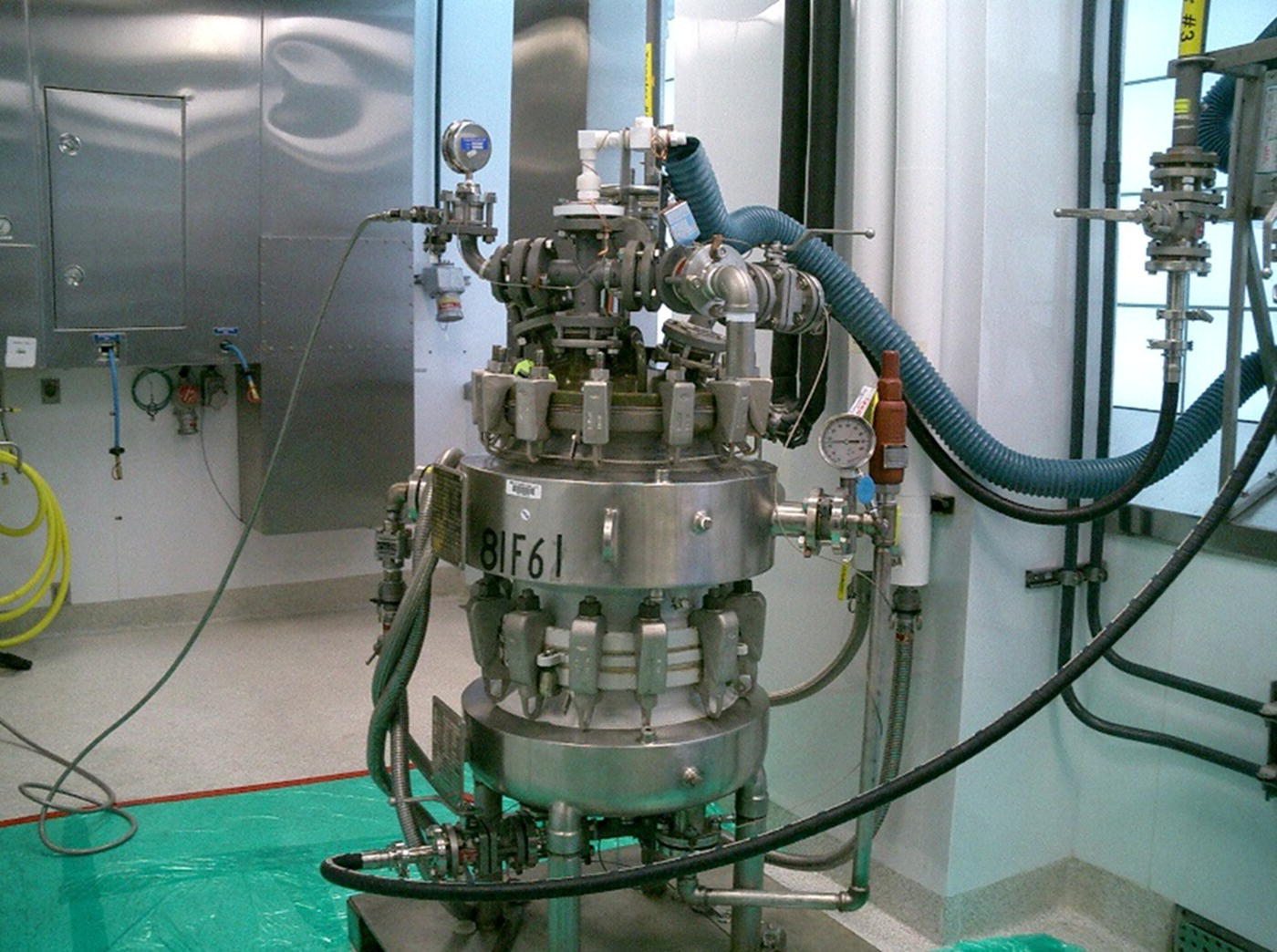
FIGURE 46.7 Nutsche filter for kilo lab or pilot plant use.
46.2.4.3.2 Dryers
Drying equipment used in pilot plants are generally contact dryers (solid in contact with heated surface) and operated in batch mode. Considerations for dryer selection include the acceptable drying time, the impact on powder properties (i.e. prevention of particle agglomeration, particle attrition, or crystallographic form change), and the explosibility of the dry powder. Commonly found types of dryers include tray dryers, agitated dryers, tumble dryers, etc. Drying equipment used in kilo labs is generally limited to tray dryers and filter dryers. Pilot plants typically standardize on a few different types of dryers, harmonizing where possible with commercial manufacturing. PAT (Raman, IR, mass spectroscopy) can also be incorporated to the dryer to monitor the off‐gas composition or solids (e.g. polymorphic form) to monitor the drying process and determine drying endpoint:
- Tray dryer: A tray dryer is a large oven connected to a vacuum pump or inert gas supply. Product is loaded onto trays (metal or glass), which are placed onto shelves in the dryer. Sampling is achieved by interrupting the drying cycle and removing material from the trays. The dry product is manually unloaded from the trays into product containers. The tray dryer design offers little containment, and additional engineering controls are needed to provide worker protection. Like Nutsche filters, tray dryers are typically not used for other than laboratory amounts of potent compounds unless additional containment is included in the equipment design.
- Agitated dryer: The agitated dryer is also usually connected to a vacuum pump during the drying operation and typically has a sampling port on the side of the filter wall that facilitates contained sampling operations. Typical agitated dryer designs include conical dryers, spherical dryers, and pan dryers with screw or blade agitations offering different shear profiles and attrition risk. A standard agitation protocol (intermittent vs. continuous, agitation rate) can be deployed and then varied as needed based on the project need to achieve the desired drying endpoint and powder properties. Multiple types of sampling ports are available to allow for monitoring of the drying progress.
- Rotary dryer: The rotary or double‐cone dryer, similar to the tray and filter dryer, is connected to a vacuum and heating source. In place of agitation, the rotary dryer rotates axially to gently mix the product during the drying unit operation.
Product recovery yield from drying equipment can vary based on the size and configuration of the dryer. Due to the possibility of large losses to the dryer (10–20% yield), product recovery may be an option to ensure campaign deliverables are met. The recovery can be performed through the dissolution of the remaining product left within the equipment. This is often referred to as heel dissolution. The equipment design may be inclusive of the ability to recover dissolved product solutions for further processing including sprayball charge lines and liquid‐sealed discharge capabilities.
46.2.4.4 Equipment Cleaning Design
Equipment, although designed for the needs of the process, also incorporate post‐process cleaning and contamination removal. Since drug substance manufacturing typically is performed in multiproduct equipment and facilities, process equipment must have the ability to prevent cross contamination from past processes. The equipment design may include the use of fixed or dynamic spray devices, or sprayballs, to ensure total wetting of the interior surfaces, inclusive of the reactor riser and condenser. In cases where sprayballs are not incorporated into the design, alternatives such as solvent reflux or liquid filling of the equipment may be necessary to rinse and wet all surfaces. Additionally, equipment may require some disassembly to complete a thorough hand cleaning and visual inspection.
46.2.5 Engineering Control Equipment
Engineering control equipment provides the primary level of protection for the worker from the hazards associated with chemical or pharmaceutical exposure during process operations. The engineering controls should provide protection for the specific operations where the operator exposure levels (OEL) are above a threshold of concern for an individual chemical, intermediate, or API (see Section 46.3). Typically the operations with the greatest potential for worker exposure are charging, discharging, sampling, milling, and cleaning operations. The standard designs for equipment used in these operations do not provide sufficient containment on their own, and another layer of protection is needed. Common types of engineering controls found within pilot plants and kilo labs are flow hoods, barrier isolation technology, solids transfer technology, and sampling technology.
46.2.5.1 Flow Hoods
Flow hoods employ various technologies to achieve their containment target. Common types of flow hoods found in the pharmaceutical industry are downflow hoods and chemical fume hoods. Downflow hoods provide a high level of solids containment by directing the flow of particulates in the air away from the worker and into the hood exhaust system and particulate filtration system. Chemical fume hoods provide a constant flow of air from the front of the hoods that is exhausted to the atmosphere directly or via a filter. Fume hoods are effective for reducing exposure levels from chemical vapors and tend to be less effective for solids containment compared with downflow hoods. The small scale of equipment used in kilo labs often enables installation of the reactor vessels within the fume hood or downflow hood, allowing for sufficient worker protection during operations presenting the greatest risk of exposure. Figure 46.8 shows an open filter design often found in kilo labs. The filter design enables manual manipulation of the wet cake and facilitates troubleshooting during filtration yet offers no protection to the worker from the product. The filter must be placed in a downflow booth or used with other engineering controls (including PPE) to ensure adequate worker protection.

FIGURE 46.8 Open filter often found in kilo labs.
46.2.5.2 Isolator Technology
Barrier isolation technology directly separates the worker from the exposure hazards via a temporary or permanent wall. The barrier isolator may resemble a box and enables the worker to perform all of the necessary standard operations (i.e. charging, discharging, sampling) through the use of glove ports and pass through ports through the walls of the box. This technology may be incorporated into standard types of equipment such as reactors, filters, and mills at both the pilot plant and kilo lab scales to perform operations involving potent or highly potent compounds (see Figure 46.2c). Additionally, isolator technology may be used to handle hazardous solids that require inerted conditions. Further information is provided in Section 46.3. Additionally, disposable isolators may be utilized in place of the fixed isolator design that allows for a lower capital investment and ease of cleaning (see Figure 46.9). Barrier isolators contain the particulates from the outside environment through the use of high efficiency particulate air (HEPA) filters on the exhaust. Where needed, the degree of containment achieved can be increased by maintaining the internal environment in the isolator under a negative pressure differential. Isolator technology is commonly used today where primary equipment design is insufficient to provide sufficient worker protection during operation.

FIGURE 46.9 Disposable isolator technology for a mill.
46.2.5.3 Solids Transfer Technology
Solids transfer technology significantly reduces the worker exposure levels resulting from the charging/discharging operation. The solids are pre‐charged/transferred into the charging bags in a contained location prior to processing within the chemical processing facility. The technology allows material charging and discharging operations to be performed in a closed system preventing direct worker exposure to the compound as well as the room contamination that results from open handling. Some common solids charging and discharging technologies used in the pharmaceutical industry are barrier isolators, split butterfly valve technology, powder transfer systems, disposable containment systems, and continuous liners. The barrier isolator can be installed as a hard wall or soft wall isolator at the equipment charge or discharge ports to provide the desired level of containment. Split butterfly valve technology supports low operator exposure through the use of active and passive valves. The active and passive valves are mounted separately to the charge/discharge vessel nozzle and the equipment as shown in Figures 46.10 and 46.11. The solids transfer operation can proceed only when the active and passive valves are joined or docked together. Continuous liners made of pliable material are used to increase the flexibility of solids containment. A continuous liner mounted as the receiving vessel can be crimped to isolate an amount of solids and then cut to form a separate bag containing the solids without breaking containment.
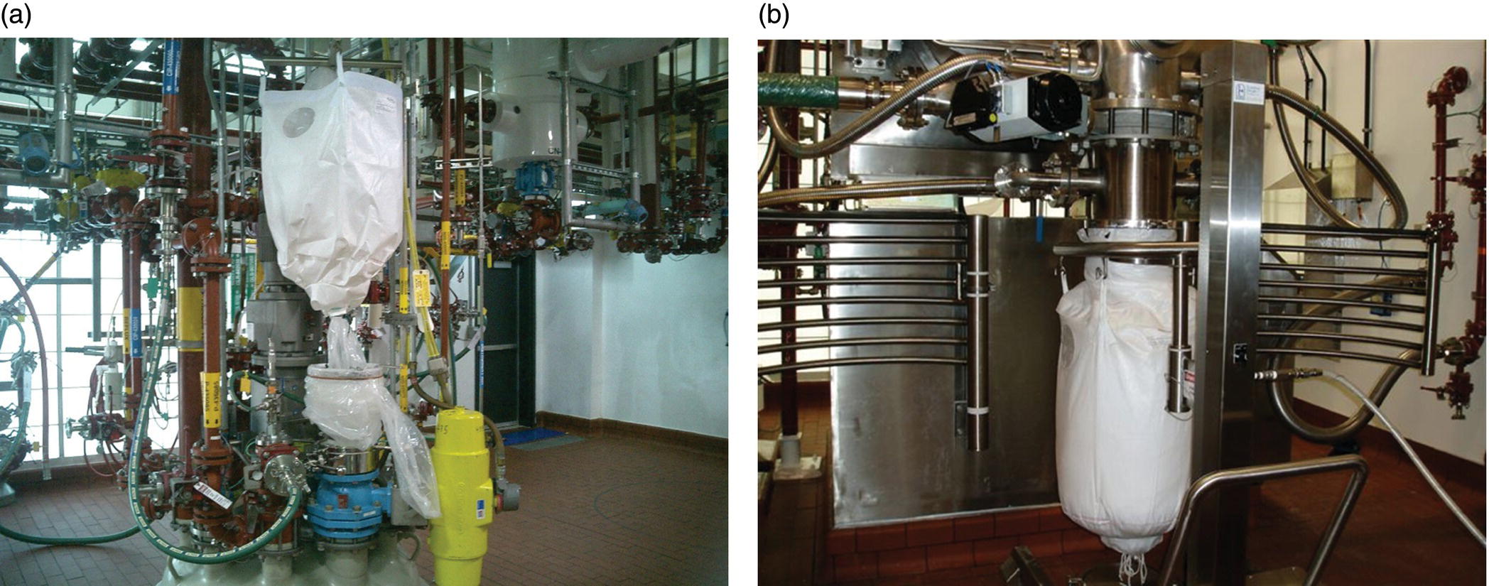
FIGURE 46.10 Solids handling using split butterfly valve technology. (a) Material charge into a reactor using a disposable isolator. (b) Discharging the wet cake from a centrifuge into a flexible liner.
FIGURE 46.11 Schematic of closed discharge system consisting of discharge drum in laminar flow booth connected by continuous liner.
46.2.5.4 Sampling
Engineering controls used during sampling operations are designed to minimize operator exposure potential during the direct sampling of reactors via pressure or caused by sample spills. This is of increased importance when the intermediates and/or APIs are highly potent, have substantial toxicological concerns, or are at high temperature or pressure conditions. To minimize operator exposure during the sampling operation, barrier technology, closed vent sampling devices, or similar technologies may be installed within the scale‐up facilities as shown in Figure 46.12.
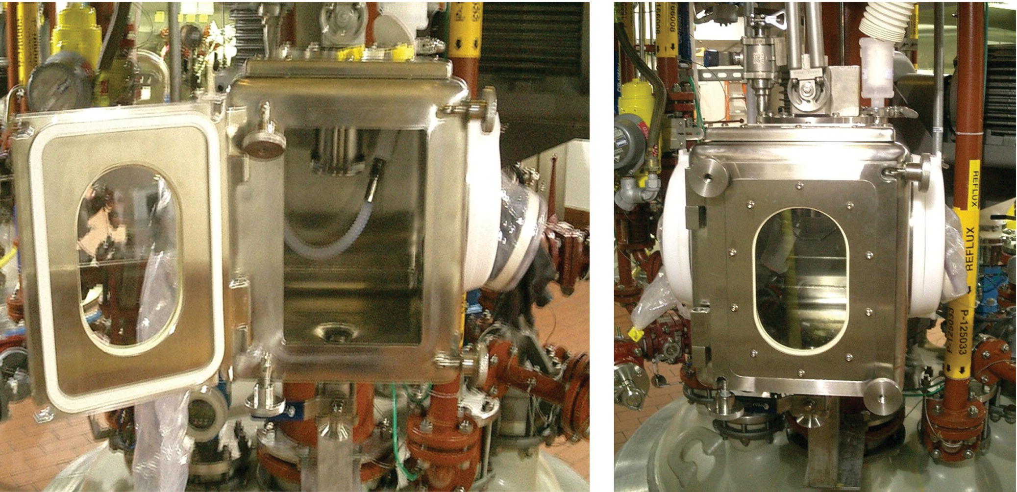
FIGURE 46.12 Sampling device contained within a glovebox shown open on the left and closed on the right.
46.2.6 Process Automation
Today, most pilot plant facilities have modern process control systems that provide basic control of primary process parameters such as temperature and pressure. Less common to pilot plant facilities are the recipe‐driven process automation systems (recipe control) found in manufacturing, which may feature advanced process control and business systems interfaces. Most pilot plants will also have data historians to capture process data (i.e. pressure, temperature) as well as events (i.e. valve opening, changed set points). Kilo labs that are an extension of laboratory systems may have basic control for reactor temperature and pressure, while others deploy process control systems for regulatory control. Some kilo labs have the extensive process control systems found in pilot plant facilities.
The approach to process control and automation in kilo labs and pilot plants differs from that in manufacturing facilities. Commercial products are manufactured using validated processes supported by knowledge of the process design space. Goals of the process control system are to ensure efficient and consistent execution of the chemical process, minimizing process excursions and reducing batch to batch variability. Integration of the process control system with other manufacturing execution systems allows for greater efficiency in product release and inventory management, leading to reduced operating costs. Process data is collected to support batch release and continuous process improvement. In contrast, processes in pilot plant facilities span early to late development and are typically run only a few times. Process changes are expected between batches and campaigns! The primary goal of the data collection system is to generate process knowledge and provide development scientists access to process data. The process control system should be designed for flexibility and robustness to accommodate changing requirements from each process, to facilitate process troubleshooting, and to enable chemical operators to focus on the process.
Kilo lab and pilot plant process control system have the following general goals:
- Provide control of process and utility parameters to maintain safe operation and reduce variability of the process. This will reduce the risks encountered when scaling process chemistry from one scale to the next.
- Notify the operator when the process or utility is out of range.
- Document what has occurred during the batch to support regulatory requirements and review. This may range from a simple trend of temperature to a log of all continuous process data and discrete events that have occurred.
- Help reduce development time by enabling process understanding and process robustness through knowledge capture.
46.2.6.1 Control Systems
A typical batch reactor control system with temperature and pressure control loops is shown in Figure 46.13. The control system relies upon primary instruments, such as thermocouples and pressure sensors, and control elements, such as control valves, which are wired back to stand‐alone controllers or to a computerized process control system such as a DCS where hundreds of control loops are executed. These sensors also facilitate capture of continuous data (e.g. temperature) and discrete‐event data (e.g. when does a valve open and close during a charge).
FIGURE 46.13 Batch reactor with typical split range configuration to control batch temperature.
The basic regulatory control process, PID (proportional–integral–derivative) controller, is still used in most pilot plants though there are more advanced approaches such as model predictive control. In modern pilot plants, the flexibility inherent in these digital systems not only allows for plug and play of various unit operations equipment but also allows the control strategies to be easily changed to meet the needs of each product, facilitates regulatory compliance, and supports generation of process knowledge.
46.2.6.2 Recipe‐Driven Batch Control
A “batch” consists of a sequence of unit operations to produce a product. For example, to carry out a reaction, a typical sequence of events is shown in Table 46.1.
TABLE 46.1 Typical Sequence of Events
| Sequence | Event |
| 1 | Inert the vessel with nitrogen |
| 2 | Charge solvents, substrates, and reagents to vessel |
| 3 | Turn on agitator |
| 4 | Heat to reaction temperature |
| 5 | Hold until reaction is complete as determined by sampling |
| 6 | Sample by pressurizing vessel, withdrawing sample, and depressurizing |
| 7 | Cool the vessel and crystallize product |
| 8 | Transfer the product to filter |
| 9 | Dry the product |
The instructions or recipe to execute the sequence is written in the control software and includes the parameters specific to the process. The recipe will contain set points and alarm limits for each step. It can also select the desired control strategy, such as jacket temperature or batch temperature control.
In 1995, the ISA‐S88 batch manufacturing standard was issued describing the definition and control of batch processes.b At the core of the standard is the separation of the product knowledge from equipment capability, the “S88” model.
“S88” provides a logical, consistent structure for building batch recipes as shown in Figure 46.14, which combines these elements. The “recipe” sequences the different “unit procedures” such as those described in Table 46.1. Each unit procedure consists of a series of “operations” (e.g. heat, hold, sample, cool) that contain parameters (e.g. set points and limits) specific to that step. Each operation then consists of a series of “phases” that instruct the equipment‐specific elements to carry out that operation (open valve X‐101 on reactor R‐101). During the execution of the recipe, the control system captures what was done (operations and phases), when it was done, who did it (by electronic signatures), and how it was done (process data capture of continuous, temperature and discrete data, weight of a drum charge).
FIGURE 46.14 S88 procedural model.
With a control system using an S88 recipe approach and a process and event data historian, a complete record of the batch operations can be obtained to support development, quality, and regulatory requirements. Phases and operations are general purpose and become process specific when the parameters for the process (e.g. reaction temperature, hold time) are added.
46.2.7 Equipment Commissioning and Startup
When starting up a new or renovated facility or new equipment in an existing facility, the building systems and process equipment must be tested to ensure that the design specifications are met. This is required for adherence to regulations (cGMP and EHS) and good engineering practices (GEP). The standard processes to ensure that a system or piece of equipment is started up, qualified, and rendered ready for use in a pharmaceutical environment consist of commissioning, qualification, and validation (CQV). The CQV plan includes acceptance test criteria and an impact analysis to evaluate the impact of the system or equipment on the quality of the product produced (direct, indirect, or no impact).c The outcome of the impact assessment determines the extent of testing required for an individual system or equipment.
The Factory Acceptance Test (FAT) entails sending a team to the equipment manufacturer's location to execute an approved document geared toward assessing that the equipment can perform as specified. The goal is to ensure that the equipment is suitable to be shipped and installed.
Commissioning is an engineering approach of bringing a facility and/or equipment into an operational state. For qualified systems, commissioning activities can overflow into the Site Acceptance Test (SAT). For a nonqualified system, the commissioning is usually more extensive since there is no subsequent activity to ensure operational readiness.
The SAT is performed at the processing site (pilot plant or kilo lab) after the equipment has been installed. It is usually more involved than the FAT as it needs to thoroughly check out the equipment and its interface to the facility, rather than just ensure that the equipment is complete enough to allow for shipment. While it is possible to leverage the work at the FAT to reduce the SAT activities, careful consideration must be given to the installation work and how the final facility conditions differ from the factory (vendor) conditions.
The next phase of the process is the qualification, which is captured in a series of protocols to confirm the installation, operation, and performance of the equipment. Installation qualification (IQ) confirms that the correct equipment has been installed as specified in the design documentation. It is a documentation review that compares nameplate data (serial number, model number, pressure rating, etc.) with the appropriate specification to ensure compliance with the design. Additional information is also collected for analysis and future use including materials of construction, construction techniques, testing, and similar information. The operational qualification (OQ) is a protocol to systematically test the equipment to ensure that it can perform according to the user requirements for the equipment. Equipment classes tend to have similar check out requirements for individual equipment within that class. Examples of reactor class testing include pressure, temperature control, and agitation testing.
The performance qualification (PQ) is perhaps the most detailed manner of check out due to the inclusion of a test specification. Water and nitrogen system are the two most common systems that require PQs in the pilot plant and kilo lab. This is to ensure that materials charged to the batch (i.e. water) or in contact with the batch (i.e. nitrogen for inerting) meet the required quality specifications.
Successful startup and qualification of equipment and facility systems requires a systematic approach. The employment of FAT, SAT, IQ, OQ, and PQs provides a consistent, methodical means to prove facility integrity. Subsequent changes to the facility are managed using a change management program to ensure that facility and equipment integrity is maintained.
46.3 OPERATING PRINCIPLES AND REGULATORY DRIVERS
The design and operation of scale‐up facilities in the pharmaceutical industry is influenced by a matrix of regulatory guidelines. Current good manufacturing practices (cGMPs), established to ensure the quality of the drug delivered to the patient, overlay EHS regulations at the local, state, and federal level established to protect the worker, the community, and the environment. cGMPs must be followed when producing API for clinical studies to ensure that the quality and purity of the drug substance is adequately controlled. Guidelines for cGMPs are governed by the regulatory health authorities, such as FDA and the EMA. The guidelines of each agency may differ, and substantial effort has gone into establishing a consistent set of practices across agencies through the International Conference on Harmonization (ICH).d Scale‐up facilities located in the United States are governed by EHS agencies that include the Environmental Protection Agency (EPA)e, Occupational Safety Health Authority (OSHA)f, and equivalent state agencies. Equivalent agencies govern chemical process operations outside of the United States. In many cases, the design of a compliant EHS programs can be structured around the scale of operations. Kilo labs are commonly classified as laboratories, which enables these facilities to fall under the local, state, and federal regulations for laboratories. In most cases, pilot plants operate at a scale that precludes laboratory classification and must comply with regulations established for plant scale of operation and purpose. Additional EHS regulations, such as the Toxic Catastrophe Prevention Act or TCPA in the United States, apply where the quantity of listed hazardous chemicals exceeds a threshold value.
The expectations set by cGMP and EHS guidelines are shared in many areas. Most companies develop an integrated approach to operating procedures, work practices, and staffing to more effectively meet safety and quality requirements. Once established, robust training, documentation, and monitoring programs ensure compliance against regulations.
46.3.1 Process Safety
Prior to the implementation of an intermediate or API process step into a kilo lab or pilot plant, the chemistry and process details must undergo a process safety evaluation. The safety evaluation should provide data to determine the thermal hazards of the solids, key process streams, and any relevant off‐gassing data. The safety evaluation should also examine the physical properties, toxicity hazards, fire and explosion hazards, and hazardous interactions between different chemicals to determine the safety risks associated with running the process in a scale‐up facility. For projects that are further in development, a safety evaluation on the powder properties of any isolated intermediates and the API should be completed. The complete evaluation should be used to determine the intrinsic safety of the process design and whether a process can be safely implemented at the desired scale.
During the transfer of process knowledge from the process development group to the plant operations group, an assessment of the process hazards should be completed following a standard methodology to identify the process safety risks of execution into the specific scale‐up facility. Some common methodologies used for the hazard assessment are a what‐if analysis, checklist of hazards, process hazard analysis (PHA), hazard and operability study (HAZOP), failure mode and effect analysis (FMEA), or fault tree analysis. The data from the safety evaluation, plant equipment details, plant procedures, and the intended process batch instructions should be used to develop the safety assessment. The intent of the assessment is to address hazards from the process, consequences of failure from engineering and administrative controls within the plant, and potential human errors. Any process changes proposed after the initial hazard assessment is completed should be examined prior to introduction to the scale‐up facility using the facility management of change policy to ensure that all safety precautions are taken. Further information is available in Chapter 3 and related.g,h
46.3.2 Current Good Manufacturing Practices
The Quality Management section of ICH Q7Ai specifically states that “quality should be the responsibility of all persons involved in manufacturing” and that each individual manufacturer is responsible for establishing and documenting effective quality systems to manage quality of products produced both internally and through external partners. cGMP can be classified into six quality systems: facilities and equipment, production, packaging and labeling, material systems, quality, and laboratory controls. Each requirement listed in ICH Q7A will map to one of the six systems (Figure 46.15).
FIGURE 46.15 The six system approach to quality.
These systems address review of completed manufacturing records for critical process steps prior to the release of API, making sure that equipment used for manufacturing is maintained, calibrated, and fit for its intended use and that the proper level of documentation for all activities is reviewed, complete, and accurate. An internal audit program designed to ensure that a state of compliance is maintained must be established, including a defined audit frequency with documented audit findings and corrective and preventative actions (CAPAs) to address identified quality risks.
A sound personnel training and qualification program is an important element of the cGMPs. The roles and responsibilities for employees associated with pharmaceutical manufacturing facilities and operations should be defined, documented, and maintained. Requirements for education, experience, general training, job function training, proper hygiene and sanitation habits, and suitable clothing worn during manufacturing or lab operations are included. A comprehensive and well‐documented employee qualification program assists operations managers in assigning the right employee with the right skill set to the right task in compliance with cGMP.
cGMP considerations for scale‐up facilities and equipment are described in Section 46.2 and include design, construction, and startup activities. Facility and equipment design and construction should facilitate maintenance and cleaning, minimize contamination of the product, and provide adequate control systems. Materials of construction for product contact equipment are also an important consideration. Materials that are incompatible with process streams can contribute to quality issues, potentially rendering the product unusable. Process safety issues may also result where the introduction of contaminants into the process stream causes an unexpected reaction. CQV activities are completed to demonstrate that the facilities, equipment, and systems were constructed as designed and are fit for their intended use in the manufacture of APIs and chemical intermediates. Additional facility considerations include material management such as material receipt, identification, sampling, storage, and separation of released and unreleased input materials, intermediates, and APIs.
Proper facility and equipment qualification should be maintained through a change management program for systems and equipment that impact the quality of the API and/or chemical intermediates. Written procedures for facility and equipment maintenance and cleaning operations should be designed to promote consistent execution over time independent of an individual operator.
Documentation and records is one of the most visible cGMP requirements. This is the primary evidence of “what, when, who, and how” as it relates to an operation or task. Documentation requirements vary by task and may include what task was performed, who performed it, when it was performed, how it was performed, and reconciliation of any deviation from the expected procedure. The documentation is the link to ensure that an operation or task was completed as intended and that the impact of any deviation on the quality of the outcome is evaluated and understood. cGMP documentation includes equipment cleaning records, laboratory (analytical) controls, training records, and batch records, which document the execution of the manufacturing process. Batch records contain input material information, a description of executed unit operations, analytical control results, and process data. They should also contain an adequate explanation of any process deviations that occurred during processing. Any changes to batch records during execution should follow a change management program that includes appropriate comment to reconcile the change with the original entry.
46.3.3 Health and Safety
Kilo lab and pilot plant operations include the use of hazardous chemicals that may be toxic, flammable, corrosive, and/or explosive. The health and safety of the employees must be the highest priority, and worker protection programs should be in place before hazardous chemicals are introduced into the facilities. Regulations governing worker and workplace safety can vary substantially across the world, and many companies have established a minimum standard for all of their facilities to supplement country, regional, and local regulations. In the Unites States, OSHA sets standards to ensure worker and workplace safety; the standards can be found under the Regulation Standard 29 CFR 1910 Occupational Safety and Health Standards.j Table 46.2 lists some of the regulations under 29 CFR 1910. A chemical hygiene plan (CHP) or similar program is typically developed for kilo lab and pilot plant facilities to ensure compliance with OSHA standards. The plan or program consists of policies and procedures around specific topics that define the operational safety framework, including hazard communication, occupational exposure, PPE, and the procurement.
TABLE 46.2 Some US Health and Safety Regulations for Kilo Labs and Pilot Plants
| Topic | Regulation Standard (29 CFR) |
| Emergency action plans | 1910.38 |
| Occupational noise exposure | 1910.95 |
| Process safety management of highly hazardous chemicals | 1910.119 |
| Hazardous waste operations and emergency response | 1910.120 |
| Permit‐required confined spaces | 1910.146 |
| The control of hazardous energy (lockout/tagout) | 1910.147 |
| Hazardous (classified) locations | 1910.307 |
| Air contaminants | 1910.1000 |
| Hazards communication | 1910.1200 |
| Occupation exposure to hazardous chemicals in laboratories | 1910.1450 |
| Hazardous materials | 1910 Subpart H |
| Personal protective equipment | 1910 Subpart I |
| Fire protection | 1910 Subpart L |
46.3.3.1 Hazards Communications
A well‐defined hazard communication procedure is essential to understanding, accessing, and communicating the hazards associated with chemicals used in the kilo labs and pilot plants. Required elements include a hazard determination process, a procedure for management and use of material safety data sheets (MSDS), proper container labeling requirements, and effective information and training on hazardous chemicals.
The hazard determination process should involve the evaluation of chemicals purchased for use in and produced by the kilo lab and pilot plant facilities to determine if they are hazardous. Hazard information for chemicals that are purchased is contained in the MSDS provided by the vendor. For compounds produced as part of the research and development process, the company producing the compound is responsible for generating the MSDS. MSDS information for all hazardous chemicals used in the scale‐up facilities should be made available to the operating staff.
An MSDS contains the chemical name of the compound as found on the label and other common names in addition to any available hazard information. If the material is a mixture, the MSDS will list the major components and nominal composition. The types of hazard information commonly found are related to: the properties of the material, such as toxicological information, stability and reactivity, exposure control, environmental impact (i.e. ecological concerns and disposal procedures), and procedures to handle the material (i.e. storage, accidental release measures, and transportation information). There are also additional sources for hazard information beyond that found on the MSDS [4].k
Proper labeling of hazardous chemical containers is another vehicle for hazard communications. The identity of the chemical, the appropriate hazard warning, and the name of the chemical manufacturer or other responsible party must be listed on the container. The hazard warnings may take the form of words, pictures, symbols, or a combination. It is important to note that the requirements of the hazard communication regulation do not supersede the labeling requirements of other US government regulations (i.e. DOT, EPA).
The hazard information for hazardous chemicals and appropriate training must be made available to all employees and contractors who have the potential to come in to contact with the chemical. The information and training should include the details of the hazard communication program, the physical and health hazard of chemicals in the labs or plant, and the methods of protection to prevent chemical exposure.
46.3.3.2 Occupational Exposure for Pharmaceutical Compounds
Companies are responsible for developing the hazard information for research and development compounds. There is often limited information on the compound early in development. Therefore, a variety of methods, including toxicology studies and chemical structure‐based assessments, are often used to develop the information needed to evaluate the potential hazards to employees within the laboratories and scale‐up facilities. An evaluation of the available data is typically performed by an industrial hygienist, who assigns an exposure control limit (ECL) to the compound if sufficient data is available. It is often not feasible to assign a single number ECL early in pharmaceutical development, and most companies use a performance‐based exposure control band strategy, assigning the compound into a control band. The ECL for each control band are set with consideration of engineering control technologies, PPE, procedural controls, and other available tools to mitigate the risks of worker exposure as required [5]. The data generated from the toxicological evaluation and testing is typically added to the MSDS for the API or intermediates.
Although, there is not one standard control band classification used across the pharmaceutical industry, the National Institute for Occupational Safety and Health (NIOSH) defines targeted control bandsl as detailed in Table 46.3. Based on the control band assignment, the handling procedures and industrial hygiene sampling (facility surface testing), for a compound in the laboratory, kilo lab, and pilot plant, are designed to ensure that the potential worker exposure is controlled or contained within acceptable limits. Engineering controls should be used as the primary containment strategy (Section 46.2.5) supplemented by PPE as necessary to provide redundancy. PPE should not be used as the primary control.
TABLE 46.3 NIOSH Control Banding
| Band No. | Target Range of Exposure Concentration | Hazard Group | Control |
| 1 | >1–10 mg/m3 dust >50–500 ppm vapor |
Skin and eye irritants | Use good industrial hygiene practice and general ventilation |
| 2 | >0.1–1 mg/m3 dust >5–50 ppm vapor |
Harmful on single exposure | Use local exhaust ventilation |
| 3 | >0.01–0.1 mg/m3 dust >0.5–5 ppm vapor |
Severely irritating and corrosive | Enclose the process |
| 4 | <0.01 mg/m3 dust <0.5 ppm vapor |
Very toxic on single exposure, reproductive hazard, sensitizer | Seek expert advice |
Employee exposure – controlled with engineering controls, procedures, and PPE – is also prevented by employing sound industrial hygiene sampling following the completion of a campaign. For example, following a campaign using highly potent compounds, equipment exterior and facility surfaces are decontaminated and then sampled to ensure potent compounds have been removed to prevent worker exposure. The sampling protocol and limits are defined by the facility and based on operator exposure guidelines.
46.3.3.3 Personal Protective Equipment (PPE)
The proper selection and use of PPE is important to worker safety in the kilo lab and pilot plant. Various types of PPE are available and should be used as appropriate to mitigate risk of chemical exposure. A standard policy defining the minimum requirements for all workers and visitors is typically developed for each facility based on facility operations and construction. For kilo labs and pilot plants, minimum requirements generally consist of the items found in Table 46.4.
TABLE 46.4 Common Minimum PPE Requirements for Kilo Labs and Pilot Plants
| Type of PPE | Common Requirements |
| Eye protection | Safety glasses with side shields. Protection should meet the ANSI Z87 standard for occupational and education eye and face protection |
| Foot protection | Steel‐toed shoes that are static dissipating |
| Protective apparel | Fire‐retardant uniform or laboratory coat Chemical‐resistant gloves and clothing |
| Head protection (if applicable to facility) | Protection should meet the ANSI S89 standard for protective headwear for industrial workers requirements |
There may be additional requirements for PPE for use when handling specific chemicals or performing certain operations where the PPE is applicable to the hazards involved. The selection criteria for protective face shields, glove type, respiratory protection, and outer safety garments should include potential hazards as well as known hazards.
Gloves provide a barrier between the worker and chemical or physical hazard. When choosing a glove, the kilo lab or pilot plant operator should select one that provides the type of protection necessary for the operation being performed and also provides the dexterity necessary to complete the task. There is no single type of glove that provides protection against all chemicals, and it is important to carefully select the appropriate glove for the operation. The respiratory protection used in a kilo lab or pilot plant must provide protection against gas, vapors, mists, and solid particulates. The type of respiratory protection selected must be able to maintain the employee's exposure levels below permissible levels. The types of respirators currently used in pharmaceutical scale‐up facilities include air‐purifying respirators, powered air‐purifying respirators, and supplied air respirators. The MSDSs for the chemicals to be used and additional literature sources should be consulted to determine the appropriate glove and respirator selection.
46.3.3.4 Management of Hazardous Chemicals
Procedures should be established for the procurement, distribution, and storage of hazardous chemicals that provide for adequate control over chemical inventory to mitigate the risk of safety‐related issues. Consideration of interactions and incompatibilities between different classes of chemicals should be included at all phases of the management process. The design and operation of chemical storage and staging areas must comply with regulations for segregation of certain hazardous chemicals.
46.3.4 Environmental
Pharmaceutical kilo labs and pilot plants handle larger quantities of hazardous and toxic chemicals than standard laboratories and have a responsibility to prevent accidental release of substances into the environment. Local, state, and federal governments have established laws and regulations to prevent the accidental release of hazardous substances into the environment. These laws and regulations typically require that the facilities have procedures and safeguards for air pollution and controls, site management of toxic substances, and waste disposal management. Examples of US environmental regulations are the Clean Air Act, Resource Conservation and Recovery Act (RCRA), and Toxic Substances Control Act.
The government regulations for air pollution are set to provide protections for the public health against hazardous pollutants. The regulations aim to reduce the overall emissions by setting limits on certain pollutants, setting performance levels for pollutant controls, managing environmental permit programs, and providing enforcement powers. Facilities, such as kilo labs and pilot plants, which produce above certain quantities of pollutants, as defined by local, state, or federal regulations, are required to obtain operating permits that limit air pollutants. The permit will typically require the facilities to report the actual air pollutants generated through the use of theoretical models. A typical emissions report provides the actual emissions produced categorized by type of pollutant and documents that the emissions do not exceed the allowable permitted quantity for each type of pollutant. Scale‐up facilities will typically reduce or limit air pollutants with air emission controls, such as condensers, cryogenic condensers, cold traps, gas scrubbers, and thermal oxidizers connected to the facility or equipment train. When properly engineered, these devices can significantly reduce or eliminate specific pollutants.
46.3.4.1 Waste Disposal
Scale‐up facilities must have a waste management program for waste that is generated during processing. There are local, state, and federal government laws and regulations for the management of hazardous waste and nonhazardous waste. Hazardous waste is considered as any waste with properties that makes it dangerous or capable of having a harmful effect on human health or the environment. Nonhazardous solid waste is not based on any physical form (i.e. solid, liquid, gaseous) but is any waste that is generated by industrial process or non‐process sources that does not meet the classification of hazardous waste. The regulations surrounding hazardous waste requires control from “cradle to grave.” Procedures for the generation, storage, treatment, transportation, and disposal of hazardous waste must be developed to ensure compliance with regulations.
46.3.4.2 Emergency Response for Spills and Accidents
An emergency response plan should be established for kilo labs and pilot plants to enable rapid and appropriate response. The response plan should include EHS hazards associated with hazardous material spills, fires, and explosion emergencies, proper notification details, the containment and control of the hazard, cleanup and restoration of the area, a list of the emergency response groups, the evacuation plan, and reporting requirements. Some companies train operating staff in kilo labs and pilot plants, who are familiar with the hazards associated with the chemicals, to provide the first response to spill cleanup. Emergency response procedures should be used when there are properties of the hazardous substances, circumstances of the release, and other factors in the work area that require more than an incidental cleanup.
46.3.5 Programs and Procedures
Procedures and programs developed for kilo labs and pilot plants should be structured to promote compliance with cGMP, health and safety, and environmental regulations while enabling process development. Operating procedures, employee training, equipment and facility cleaning, housekeeping, maintenance, and inspection programs provide a foundation for operation of the kilo lab and pilot plant.
46.3.5.1 Operating Procedures
Operating procedures and other written instructions for kilo labs and pilot plants should provide process operators with clear instructions on how to safely operate equipment and conduct routine plant or kilo lab operations. Equipment instructions should describe startup operations, normal operations, shutdown operations, and emergency operations for the specified equipment. Additional information about equipment operating limits and an interlock or safety system list may be included. Other topics for written instructions include industrial hygiene testing, hazardous and/or toxic materials handling, hazardous waste handling, and energy control procedures required to manage the multiple sources of hazardous energy during maintenance and operations (see Section 46.3.5.3).
46.3.5.2 Employee Training
A well‐defined and documented employee training program is essential to ensuring compliance with procedures and program expectations. The training plan is role based and assigned to an individual based on his or her role within the kilo lab or pilot plant operations. The training objective may range from awareness of the topic to hands‐on application within daily operations. Awareness training will usually apply to policies or procedures where the knowledge of the general context is important but the individual is not responsible for performing the operations. Application training is used when the knowledge is necessary to perform an assigned task. Between the two is comprehension‐based training, which applies to employees that need to understand the specifics of the procedures due to their role in the organization. An essential element of a good training program is the requirement for refresher training at a specified time interval to ensure that operating staff maintain a competent skill level and knowledge needed to be compliant with regulatory requirements.
46.3.5.3 Equipment/Facility Cleaning
Equipment and facility cleaning programs are designed to reduce the risk of product cross contamination between processes. Although many facilities will have unique cleaning approaches and procedures, generally a defined plan will be in place to ensure appropriate identification of residual product in the equipment train consistent with ICH Q7A. The cleaning criteria are based on the toxicity or acceptable daily intake (ADI) of the previous product that is carried over into the next product. Since the carryover is variable based on the product dose, this parameter is also used to define cleaning limits. After the cleaning limits have been established, the post‐process cleaning is performed based on the facility procedures and equipment design. A combination of organic solvents, with acceptable solubility of the product, and aqueous detergents may be used to execute the cleaning. Once the cleaning process has been completed, equipment samples will be analyzed, and a visual inspection of the equipment will be completed to ensure process residues have been removed from the equipment train.
46.3.5.4 Housekeeping, Maintenance, and Inspection Program
Preventative programs are designed to proactively address workplace safety and ensure cGMP compliance of the facility. A housekeeping policy, preventative maintenance (PM) program, and inspection practices allow for early identification of issues and corrective actions before problems arise. A housekeeping policy for kilo labs or pilot plants will include keeping process areas clear of obstructions, ensuring clean and sanitary work areas, and the proper storage of hazardous chemicals.
PM and mechanical integrity programs help to ensure that the systems installed within the facility are functioning properly and within the design specifications. A well‐designed PM program enables determination of whether equipment replacement or calibration is necessary and allows the tasks to be scheduled with the least disruption to processing activities. The program includes examination of instruments, such as pressure gauges, transmitters, and relief valves; evaluation of wear on equipment train components such as agitator seals, pumps, and valves; and testing of facility‐related equipment such as safety showers, fire extinguishers, and engineering controls (i.e. laminar flow hoods, isolators).
A “lockout–tagout” procedure for the control of hazardous energy in a kilo lab or pilot plant is necessary when performing maintenance activities on equipment with multiple energy sources (i.e. electricity, pressure, mechanical). Maintenance on the equipment is defined as any activity performed on the equipment, including any setup, adjustment, or inspections. The procedure is necessary to prevent the unexpected energization of equipment while the maintenance is being performed causing serious injury to the employees. The basis of the procedure should contain the identification of the energy sources, proper training of the affected personnel, and periodic inspections of the energy sources. To control the hazardous energy, lockout or tagout devices should be installed on the energy sources to prevent the accidental energization on the equipment or machine. The use of locks is the preferred method for any energy control procedures as tags are only a warning against hazardous conditions. It is critical for the individual or groups of individuals who are performing the maintenance operations to confirm the de‐energization of all equipment being serviced.
A safety inspection program acts to alert the staff to any safety risks associated with inadequate housekeeping and deficiencies within the PM program. It can also provide a real‐time check on compliance with safety procedures such as labeling, hazardous chemical handling, and improper use of PPE. Completing the integration of safety and quality, the inspection program can also supplement the cGMP internal audit through identification of potential quality risks.
46.4 SUMMARY
Kilo labs and pilot plants are important tools supporting process development in the pharmaceutical industry. Designed for flexibility and responsiveness to change, they are an extension of the scientist's laboratory supporting process knowledge generation and successful introduction of new chemistries at all stages of process development. Governed by cGMP and EHS regulations, they are designed and operated in compliance with a multitude of regulations. Protection of the patient, the worker, and the environment are top priorities. Joined together, the kilo lab and the pilot plant can provide a competitive edge within process development in the pharmaceutical industry.
46.5 EXERCISE
cGMP regulations require investigation of unplanned events that occur within scale‐up facilities to determine the effect on the quality of the product manufactured. Regulations define certain elements that must be included within a compliant “quality events program”; however, individual company programs will vary. At the core of a quality events program is the investigation of the unplanned event to enable identification of the root cause and determination of the impact to the quality of the product. Corrective actions are then implemented that address the root cause mitigating the risk of a future occurrence. Facility operations at the time of the event, the state of the equipment, input materials, and the chemical process are some factors to consider during the investigation. Investigations in kilo labs and pilot plants can be further complicated where there are limitations on the process knowledge available for the product. A commonly used methodology for investigation of such events is the Kepner Tregoe process (www.kepner‐tregoe.com). A situational analysis is typically performed to determine if an investigation is needed based on the potential for impact to the quality of the product. As with any investigation, constructing a timeline and collecting “forensic evidence” are important first steps in determining if the product quality is affected.
You have been asked to lead the situational appraisal for an unplanned event that occurred in the manufacture of an API. Below is a summary of information provided to you.
Where: Pilot Plant
What: An API slurry was transferred from a crystallizer into a filter dryer using nitrogen pressure. The mother liquor was collected in a receiver downstream of the filter. After the slurry transfer was complete, the API was washed with fresh solvent charged into the filter from solvent drums to remove any residual mother liquor from the cake. The process flow diagram (PFD) for the operation in depicted in Figure 46.16. During the washing step, black particulates were observed by the operator on the top of the wet cake in the filter dryer.

FIGURE 46.16 Process flow diagram for exercise.
Background:
- The API is designated for use in a clinical phase II study.
- The crystallizer and filter dryer are used for processing of both intermediates and API.
- After each campaign, the equipment is cleaned and inspected.
- The filter dryer has been used in the manufacture of multiple products since the last PM, both intermediates and API.
- The crystallizer has not been used since the last PM was completed. It was verified as clean prior to use in this batch.
- The process stream and the crystallization antisolvent were filtered through a 1 μm filter before they were charged to the crystallizer.
- Construct the timeline for the event.
- What is your next step? Should an investigation be conducted? Explain your answer.
- Would your conclusion change if the particulates were found before the manufacture of the processing began?
Additional data:
- The black particulates were eventually determined to be a polymer frequently found in o‐rings, which are used to seal equipment to seal against the escape of gas or fluid.
- There are several o‐rings in the filter dryer assembly that come into contact with the process stream.
- The polymer is listed as incompatible with the crystallization solvent in the available literature and is known to swell after a short period of time when immersed in the solvent.
- Consider the additional data and review the PFD. What is the likely source of the black particulates observed on the filter cake?
- Is there another obvious potential source?
- Should the investigation be expanded to include other products? Why or why not?
- What actions would you take to prevent a reoccurrence?
ACCEPTABLE RESPONSES:
- Construct the timeline for the event.
Include all operations (every detail) leading up to the identification of the foreign matter. Key things to highlight may include the transfer from the crystallizer to the filter dryer, purging the transfer line with nitrogen, rinsing the crystallizer, agitation when receiving the slurry and wash, the transfer location for the wash, the charge method of the wash solvent (identification of no charge filter), pressurization of the filter dryer to isolate mother liquor and wash, and what inspections were performed throughout the process (i.e. inspection of the filter dryer prior to batch, the wet cake prior to charging the wash).
- What is your next step? Should an investigation be conducted? Explain your answer.
Identify quality implications to the batch; since the foreign matter identified is not compatible with crystallization solvent, this material may have solubilized and therefore contaminated the batch. Identify and summarize possible routes for introduction of foreign matter into the filter dryer (i.e. transfer piping, nitrogen, slurry, solvent), identify and summarize equipment failure scenarios (i.e. piping, transmitters, agitator, gaskets, charging pumps). Yes, an investigation should be conducted to identify the source, root cause, and corrective actions and to determine path forward for the use of the batch.
- Would your conclusion change if the particulates were found before the manufacture of the processing began?
No, investigation should still be conducted to understand source, root cause, corrective actions, and possible implication to previous batches.
- Consider the additional data and review the PFD. What is the likely source of the black particulates observed on the filter cake?
Since the particulates were not observed prior to introduction of the wash, and a charging filter was not used, it is likely that the material was introduced from an equipment failure on the charging pump or charging lines. This should be confirmed with an inspection of the pump.
- Is there another obvious potential source?
The foreign matter could have also been from the solvent container, if the solvent container was contaminated.
- Should the investigation be expanded to include other products? Why or why not?
Yes, the investigation team would need to understand where the pump was used and when the last maintenance was performed (or last good state of the pump).
- What actions would you take to prevent a reoccurrence?
Improved frequency of pump maintenance or inspection. Standard setup modification to include installation of a polish filter for solvent charge lines.
REFERENCES
- 1. ISPE (2004). Baseline Pharmaceutical Engineering Guides for New and Renovated Facilities, Biopharmaceutical Manufacturing Facilities, vol. 6. Tampa, FL: ISPE.
- 2. ISPE (2001). Baseline Pharmaceutical Engineering Guides for New and Renovated Facilities, Water and Steam Systems, vol. 4. Tampa, FL: ISPE.
- 3. Brauer, R.L. (2006). Safety and Health for Engineers. New York: Wiley.
- 4. Ullmann, F. and Bohnet, M. (2009). Ullmann's Encyclopedia of Industrial Chemistry. New York: Wiley.
- 5. Naumann, B.D., Sargent, E.V., Starkman, B.S. et al., Merck & Co., Inc.(1996). Performance Based Exposure Control Limits for Pharmaceutical Active Ingredients. American Industrial Hygiene Association Journal 57: 33–42.