7.5 Experiments
This section presents experimental studies on performance analysis of six SM-EEAs representing four different criteria, that is, PPI from convexity geometry via OP, N-FINDR and AN-FINDR from finding maximum simplex volume, SPCA-EEA from statistical correlation, FCLS-EEA from LSE-based fully abundance-constrained spectral unmixing, and AMEE from morphology. Three sets of experiments are conducted for performance evaluation, which are (1) six synthetic image-based scenarios discussed in Chapter 4, (2) AVIRIS and (3) HYDICE real image experiments. Since MNF is one of the most widely used techniques to perform DR in the literature, it is used for all EEAs that require DR.
7.5.1 Synthetic Image Experiments
The synthetic images used for experiments were the three scenarios of target implantation (TI), TI1, TI2, and TI3, and the three scenarios of target embeddedness, (TE), TE1, TE2, and TE3, are described in Chapter 4 and reproduced in Figure 7.12 for reference.
Figure 7.12 Three scenarios designed for TI, TI1, TI2, and TI3 and three scenarios of TE, TE1, TE2, and TE3.

Six SM-EEAs, MATLAB-PPI (PPI) with 500 skewers, 1-IN-FINDR, AN-FINDR, SPCA-EEA, FCLS-EEA, and AMEE, were implemented on these six scenarios to extract endmember pixels. Based on the ground truth in Figure 4.2 and Tables 4.1 and 4.2, there are 100 pure pixels, 20 mixed pixels, and 10 subpixels, all of which are simulated by five distinct pure mineral signatures. So, there are a total of six spectrally distinct signatures, five endmembers ![]() plus a mixed background signature b. Therefore, two sets of experiments were conducted by assuming that p = 5 to represent only five endmembers (pure signatures) and p = 6 to indicate that there are six spectrally distinct signatures (five endmembers plus a mixed background signature) present in the data. Two preprocesses were generally required for SM-EEAs: (1) DR and (2) use of a random generator to produce initial endmembers. So, in all experiments MNF was used to perform DR for TI2, TI3, TE2, and TE3, while PCA was used for TI1 and TE1 because MNF was not applicable to noise-free scenarios TI1 and TE1. Furthermore, the reduced dimensionality is set to the same value as p. In addition, to demonstrate inconsistent results caused by the use of random initial endmembers, two sets of randomly generated initial endmembers were used to initialize the six EEAs for illustration.
plus a mixed background signature b. Therefore, two sets of experiments were conducted by assuming that p = 5 to represent only five endmembers (pure signatures) and p = 6 to indicate that there are six spectrally distinct signatures (five endmembers plus a mixed background signature) present in the data. Two preprocesses were generally required for SM-EEAs: (1) DR and (2) use of a random generator to produce initial endmembers. So, in all experiments MNF was used to perform DR for TI2, TI3, TE2, and TE3, while PCA was used for TI1 and TE1 because MNF was not applicable to noise-free scenarios TI1 and TE1. Furthermore, the reduced dimensionality is set to the same value as p. In addition, to demonstrate inconsistent results caused by the use of random initial endmembers, two sets of randomly generated initial endmembers were used to initialize the six EEAs for illustration.
It should be also noted that in the following experiments the results of FCLS-EEA are absent in scenarios of TI1, TE1, TI2, and TE2 due to the fact that the endmember matrix found by FCLS for spectral unmixing was not of full rank. This is particularly true for TI and TE1 because no noise is present in the data and the number of bands is greater than the number of endmembers unless a DR is performed to reduce the data dimensionality to the number of endmembers. In scenarios of TI2 and TE2, the same issue may occur to FCLS-EEA when randomly generated initial endmembers happened to be pixels in the same target panel. Since scenarios TI3 and TE3 have simulated noise added to all image pixels including endmember panel pixels, there is no issue of ill rank in FCLS-EEA.
7.5.1.1 Scenario TI1 (Endmembers Implanted in a Clean Background)
Scenario TI1 is an idealistic case where pure panel pixels considered as endmember pixels are implanted in a clean (i.e., noise-free) background. So, there are five endmembers ![]() plus a mixed background signature b. Figure 7.11 shows respective results of five SM-EEAs, PPI with 500 skewers, 1-IN-FINDR, A1-IN-FINDR, SPCA-EEA, and AMEE using two different sets of randomly genertaed initial endmembers with p = 5 where extracted endmembers are marked by yellow circles. Interestingly, in this noise-free scenario none of five SM-EEAs extracted all five endmembers representing five distinct pure mineral signatures. Also, a comparison among results in Figures 7.13 and 7.14 shows that the results obtained by two different sets of random initial endmembers were not consistent.
plus a mixed background signature b. Figure 7.11 shows respective results of five SM-EEAs, PPI with 500 skewers, 1-IN-FINDR, A1-IN-FINDR, SPCA-EEA, and AMEE using two different sets of randomly genertaed initial endmembers with p = 5 where extracted endmembers are marked by yellow circles. Interestingly, in this noise-free scenario none of five SM-EEAs extracted all five endmembers representing five distinct pure mineral signatures. Also, a comparison among results in Figures 7.13 and 7.14 shows that the results obtained by two different sets of random initial endmembers were not consistent.
Figure 7.13 Results of endmember pixels extracted from TI1 by PPI along with five endmembers extracted by 1-IN-FINDR, A1-IN-FINDR, SPCA-EEA, and AMEE using two sets of random initial endmembers.

The results produced by PPI were also worth noting. Due to no noise present in the data, the background signature dominated the entire data and was considered as a pure signature. As a result, in this scenario the PPI counts of all background pixels produced by PPI were constant and greater than the PPI counts of the five pure mineral signatures. So, the PPI image shown in Figure 7.6 is actually a PPI count map of all image pixels, which turns out to be a binary image with black pixels and white pixels representing panel pixels and background pixels, respectively. This scenario demonstrated a crucial fact that the PPI count of an endmember did not necessarily yield the highest value. On the contrary, in many cases the PPI counts of endmembers were usually very low but they were never equal to zero.
If the same experiments are repeated for p = 6, the results are shown in Figure 7.14 where the performance of the five SM-EEAs was not improved but rather worse than those obtained by p = 7.
Figure 7.14 Results of endmember pixels extracted from TI1 by PPI along with six endmembers extracted by N-FINDR, AN-FINDR, SPCA-EEA, and AMEE using random initial endmembers.

7.5.1.2 Scenario TI2 (Endmembers Implanted in a Noisy Background)
In scenario TI2, pure panel pixels considered as endmembers are implanted into a Gaussian noise background with SNR = 20 : 1. Like scenario TI1, this particular synthetic image scene has 100 pure pixels, 20 mixed pixels, and 10 subpixels, all of which are simulated by five distinct pure mineral signatures ![]() . Similar to scenario TI1, this scenario also has a total of five endmembers plus a mixed signature, b. Figures 7.15 and 7.16 show the results of endmembers extracted by the five EEAs, PPI with 500 skewers, 1-IN-FINDR, A1-IN-FINDR, SPCA-EEA, and AMEE, with two different sets of randomly generated initial endmembers for p = 5 and p = 6, respectively, where extracted endmembers are marked by yellow circles.
. Similar to scenario TI1, this scenario also has a total of five endmembers plus a mixed signature, b. Figures 7.15 and 7.16 show the results of endmembers extracted by the five EEAs, PPI with 500 skewers, 1-IN-FINDR, A1-IN-FINDR, SPCA-EEA, and AMEE, with two different sets of randomly generated initial endmembers for p = 5 and p = 6, respectively, where extracted endmembers are marked by yellow circles.
Figure 7.15 Results of endmember pixels extracted from TI2 by PPI along with five endmembers extracted by 1-IN-FINDR, A1-IN-FINDR, SPCA-EEA, and AMEE using random initial endmembers.

Figure 7.16 Results of endmember pixels extracted from TI2 by PPI along with six endmembers extracted by 1-IN-FINDR, A1-IN-FINDR, SPCA-EEA, and AMEE using random initial endmembers.

As shown in Figures 7.15 and 7.16, all the five endmembers representing five distinct pure mineral signatures were successfully extracted by all the evalauted EEAs except SPCA-EEA. These results provide evidence that p = 5 is sufficient for SM-EEAs to be able to find all required five endmembers in Figure 7.15. This is because the performance was not necessarily improved if p = 6 is used, as shown in Figure 7.16. However, as discussed in Chapter 8, it will require p = 6, not p = 5, for an SQ-EEA to extract all the desired five endmembers because a background pixel will be always extracted before the last and fifth endmembers. Also noted in Figures 7.15 and 7.16 are PPI-extracted endmmembers, which included not only all 100 pure panel pixels but also many background pixels. This is because all pixels extracted by PPI had their PPI counts greater than zero and the PPI counts of many background pixels were actually higher than the PPI counts of panel pixels.
7.5.1.3 Scenario TI3 (Noisy Endmembers Implanted in a Noisy Background)
Scenario TI3 is simulated by directly adding a Gaussian noise with SNR = 20 : 1 to scenario TI1 where all the pure panel pixels are noise-corrupted signatures and no longer pure signatures. In this case, there are no endmembers in this synthetic image scene. Under such circumstances, an EEA intends to find the purest signatures in the image scene. Nevertheless, this scenario still contains a total of six spectrally distinct signatures, which are the five noise-corrupted endmembers plus a mixed background signature. Figures 7.17 and 7.18 show the results of endmembers extracted by the six EEAs, PPI with 500 skewers, N-FINDR, AN-FINDR, SPCA-EEA, FCLS-EEA, and AMEE with two different sets of randomly generated initial endmembers for p = 5 and p = 6, respectively, where extracted endmembers are marked by yellow circles.
Figure 7.17 Results of endmember pixels extracted from TI3 by PPI along with five endmembers extracted by 1-IN-FINDR, A1-IN-FINDR, SPCA-EEA, FCLS-EEA, and AMEE using random initial endmembers.

Figure 7.18 Results of endmember pixels extracted from TI3 by PPI along with six endmembers extracted by 1-IN-FINDR, A1-IN-FINDR, SPCA-EEA, FCLS-EEA, and AMEE using random initial endmembers.

Since the experimental results in Figures 7.17 and 7.18 were very similar to those obtained in Figures 7.15 and 7.16, the conclusions drawn for TI2 also hold for TI3. Only difference between TI2 and TI3 is that FCLS-EEA, which was absent in Figure 7.15 due to an ill-rank of the endmember signature matrix used for spectral unmixing, performed at least as well as any other SM-EEAs in extracting all the five endmembers.
7.5.1.4 Scenario TE1 (Endmembers Embedded into a Clean Background)
This scenario has 25 simulated panels added to and superimposed on background pixels. Therefore, there are no pure target endmember pixels in this scenario; rather six spectrally distinct signatures and five background-superimposed pure signatures can be considered as the purest signatures. The experiments conducted for Scenario TI are also performed for TE1 and the results are shown in Figures 7.19 and 7.20 for p = 5 and p = 6 using two different sets of randomly generated initial endmembers where the extracted endmembers by five SM-EEAs, PPI with 500 skewers, 1-IN-FINDR, A1-IN-FINDR, SPCA-EEA, and AMEE, are marked by yellow circles. As evident from these results, only AMEE was able to extract all the five endmembers.
Figure 7.19 Results of endmember pixels extracted from TE1 by PPI along with five endmembers extracted by N-FINDR, AN-FINDR, SPCA-EEA, and AMEE using random initial endmembers.

Figure 7.20 Results of endmember pixels extracted from TE1 by PPI along with six endmembers extracted by 1-IN-FINDR, A1-IN-FINDR, SPCA-EEA, and AMEE using random initial endmembers.

7.5.1.5 Scenario TE2 (Endmembers Embedded into a Noisy Background)
TE1 is different from TE1 in that it embeds clean signatures into noisy background instead of clean background. Nevertheless, TE2 still has six spectrally distinct signatures and five noise-added and background-superimposed pure signatures can be also considered as the purest signatures. Figures 7.21 and 7.22 show the results of endmembers extracted by the five EEAs, PPI with 500 skewers, N-FINDR, AN-FINDR, SPCA-EEA, and AMEE, with two different sets of randomly generated initial endmembers for p = 5 and p = 6, respectively, where extracted endmembers are marked by yellow circles. As shown in Figures 7.21 and 7.22, despite that the pure signaures have been added by noise-corrupted background signatures, the two SM-EEAs, PPI and A1-IN-FINDR, still managed to extract all five endmember pixels for p = 5 and p = 6, while 1-IN-FINDR misses one endmember pixel in the third row for p = 5 but extracts it for p = 6, AMEE failed to extract one endmember pixel in the third row for both endmember pixels in the second and fourth rows for both p = 5 and p = 7. The experiments show that except for N-FINDR increasing p from 5 to 6 did not really help.
Figure 7.21 Results of endmember pixels extracted from TE2 by PPI along with five endmembers extracted by 1-IN-FINDR, A1-IN-FINDR, SPCA-EEA, and AMEE using random initial endmembers.

Figure 7.22 Results of endmember pixels extracted from TE2 by PPI along with six endmembers extracted by 1-IN-FINDR, A1-IN-FINDR, SPCA-EEA, and AMEE using random initial endmembers.

7.5.1.6 Scenario TE3 (Noisy Endmembers Embedded into a Noisy Background)
In this scenario, a white Gaussian noise is added to Scenario TE1 where pure signatures and background signatures are corrupted by noise. In this case, the pure signatures are no longer clean as they are in TE2, but noise-corrupted. Nevertheless, these five noise-corrupted as well as background-superimposed pure signatures can be considered as the purest signatures. Figures 7.23 and 7.24 show the results of endmembers extracted by the five EEAs, PPI with 500 skewers, N-FINDR, AN-FINDR, SPCA-EEA, FCLS-EEA, and AMEE with two different sets of randomly generated initial endmembers for p = 5 and p = 6, respectively, where extracted endmembers are marked by yellow circles. As expected, the results in Figures 7.23 and 7.24 were not be as good as but comparable to those obtained for TE2, where PPI and AN-FINDR were the only two SM-EEAs able to extract endmember pixels in all the five rows for p = 5 and 7. Like TE2, N-FINDR misses endmember pxiels in the third row for p = 5, but picks it up for p = 7. Both SPCA-EEA and FCLS-EEA missed endmember pixels in one row for both p = 5 and p = 6, whereas AMEE missed endmember pixels in two rows for p = 5 and one row for p = 7.
Figure 7.23 Results of endmember pixels extracted from TE3 by PPI along with five endmembers extracted by 1-IN-FINDR, A1-IN-FINDR, SPCA-EEA, FCLS-EEA, and AMEE using random initial endmembers.

Figure 7.24 Results of endmember pixels extracted from TE3 by PPI along with six endmembers extracted by 1-IN-FINDR, A1-IN-FINDR, SPCA-EEA, FCLS-EEA, and AMEE using random initial endmembers.

7.5.2 Cuprite Data
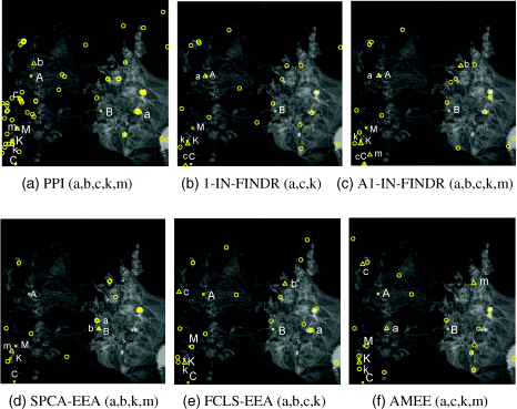
In analogy with the experiments conducted for the simulated data the six EEAs, PPI with 1000 skewers, N-FINDR, AN-FINDR, SPCA-EEA, FCLS-EEA, and AMEE are implemented on the Cuprite image scene in Figure 1.11(a) with initial endmembers randomly generated and the number of endmembers, p, estimated by ![]() in Chapter 5. The results using two different sets of randomly generated initial endmembers are shown in Figure 7.25 where target pixels extracted by algorithms are marked by yellow circles, pixels marked by yellow crosses “x” are the five ground truth mineral pixels, and the pixels marked by yellow triangles are identified by SM-EEAs corresponding to the five true mineral signatures.
in Chapter 5. The results using two different sets of randomly generated initial endmembers are shown in Figure 7.25 where target pixels extracted by algorithms are marked by yellow circles, pixels marked by yellow crosses “x” are the five ground truth mineral pixels, and the pixels marked by yellow triangles are identified by SM-EEAs corresponding to the five true mineral signatures.
Figure 7.25 Results of endmember pixels extracted by PPI along with 22 endmembers extracted by 1-IN-FINDR, A1-IN-FINDR, SPCA-EEA, FCLS-EEA, and AMEE using one set of random initial endmembers.

As shown in Figure 7.25, the endmember pixels extracted by SM-EEAs and labeled by “lower case letters” are not necessarily the same ground truth pixels labeled by “upper case letters.” These endmember pixels are identified using the correlation matched filter-based distance (RMFD) developed by Chang and Liu (2004), which is similar to (16.21) in Chapter 16 and defined as
and has been shown to perform significantly better and more effectively than the commonly used pixel level-based SAM in discrimination and identification of subpixels and mixed pixels for real hyperspectral images. In (7.23) the matrix R is the sample correlation matrix and ti and tj are two target pixels to be discriminated. Therefore, the RMFD was used to identify the 22 target pixels against the five minerals of interest, A, B, C, K, and M by RMFD via (7.23) where the signatures of the five minerals in Figure 1.11(c) were used.
7.5.3 HYDICE Data
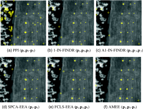
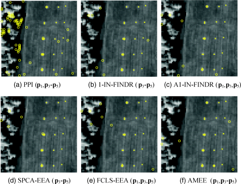
The HYDICE scene shown in Figure 1.15(a) is also used for experiments. Figures 7.26(a)–(f) and 7.27(a)–(f) show results obtained by PPI using k = 1000 skewers, 1-IN-FINDR, A1-IN-FINDR, SPCA-EEA, FCLS-EEA, and AMEE for p = 9, and 10, respectively, where none of six SM-EEAs could extract panel pixels in row 2.
The results in Figures 7.26 and 7.27 demonstrate that no matter what value of p was selected, p = 9 or 10, the six EEAs had difficulty with extracting panel pixels in row 2. This is mainly due to the fact that panel pixels in rows 2 and 3 are made by the same fabrics with slightly different paints, Oliver and light Oliver. As a result, the spectral signatures of panel pixels in row 2 are very close to those in row 3. In this case, if a panel pixel in row 3 was extracted earlier, the panel pixels in row 2 were considered as the same signature with small variations, in which case no panel pixels in row 2 would be extracted later. A similar phenomenon is also witnessed in Figure 4.12(a) and (b) where the calcite was very close to the sample mean used as the background signature so that EEAs failed to extract it once the background signature was extracted first.
Figure 7.26 Results of endmember pixels extracted by PPI and AMEE along with nine endmembers extracted by 1-IN-FINDR, A1-IN-FINDR, SPCA-EEA, FCLS-EEA, and AMEE using one set of random initial endmembers.

Figure 7.27 Results of endmember pixels extracted by PPI and AMEE along with 10 endmembers extracted by 1-IN-FINDR, A1-IN-FINDR, SPCA-EEA, FCLS-EEA, and AMEE using random initial endmembers.

