
36
FILTRATION CASE STUDIES
Seth Huggins and Andrew Cosbie
Drug Substance Technologies and Engineering, Amgen Inc., Thousand Oaks, CA, USA
John Gaertner
Process Research and Development, AbbVie Inc., North Chicago, IL, USA
36.1 INTRODUCTION
This chapter presents various approaches used to apply filtration fundamentals to develop efficient and robust processes, which consistently produce API meeting the physicochemical requirements for small molecule compounds. In these case studies, an appropriate level of understanding is developed to ensure confident determination of the design space and a scalable process. This can be challenging at times due to the complexity of the filtration processes and the limited availability of appropriate scale‐down equipment and diagnostic tools. It can be further complicated by the wide variety of equipment used for filtration.
36.2 FILTRATION DECISION TREE
Complementary to Chapter 35, this section will highlight several case studies of how filtration characteristics are used to influence process parameters and equipment selection to arrive at optimal filtration conditions. The primary purpose of characterizing filtration at the lab scale is to ensure that the performance across scales, equipment, and operating conditions does not produce any unexpected response in rate or efficiency. In the case studies that follow, the experimental lab procedure and equipment were chosen to enable rapid filtration data collection and assessment in parallel to the standard commercial process development workflows.
To perform the bench‐scale filtration characterization, any set of equipment may be used provided the filter is pressure rated across a meaningful range, and the filtration mass (or volume) may be measured at regular intervals. As outlined in the Chapter 35, the bench‐scale procedure may be used either at a single pressure to collect cake and media resistance or at several pressures to enable regression of the compressibility term. The equipment and procedures typically used in Amgen's Synthetic Technologies and Engineering labs are as follows:
- Ertel Alsop® 4T (250 ml) and/or Ertel Alsop® 10T (1.3 l) filters.
- Filter media to match the anticipated pilot‐ and commercial‐scale application:
- Typically PTFE, PP, nylon, or metal mesh with a porosity ranging from 10 to 50 μm.
- Mettler Toledo® PG or XS series scales.
- Mettler Toledo® balance link software.
The procedure utilizes a multistage pressure modulation over the course of a single experiment to regress the filtration characteristics from Eq. (36.1) [1]. Characterization is typically performed with 100 mL to 1 L of slurry. Filtrate mass is collected at one to five second intervals, where pressure is increased in a stepwise manner such that approximately one‐third of the filtration is performed at a lower initial pressure (typically 5–14 psi), a third at an intermediate pressure (10–40 psi), and the remainder at a higher pressure (30–90 psi). This process is repeated over several lots or when there are any notable changes to the solid‐state properties of the material to aid in understanding of the inherent variability and potential relationship to particle properties.
In addition to pressure (ΔP) and filtrate rate (m/t), data is collected for mass fraction of the solids (w), mass of filtrate (m), filter surface area (A), filtrate density (ρ), and filtrate viscosity (μ). This data is used along with the modified Darcy's law to regress the average cake resistance (αavg), media resistance (Rm), and compressibility index (n) Figure 36.1:
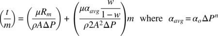
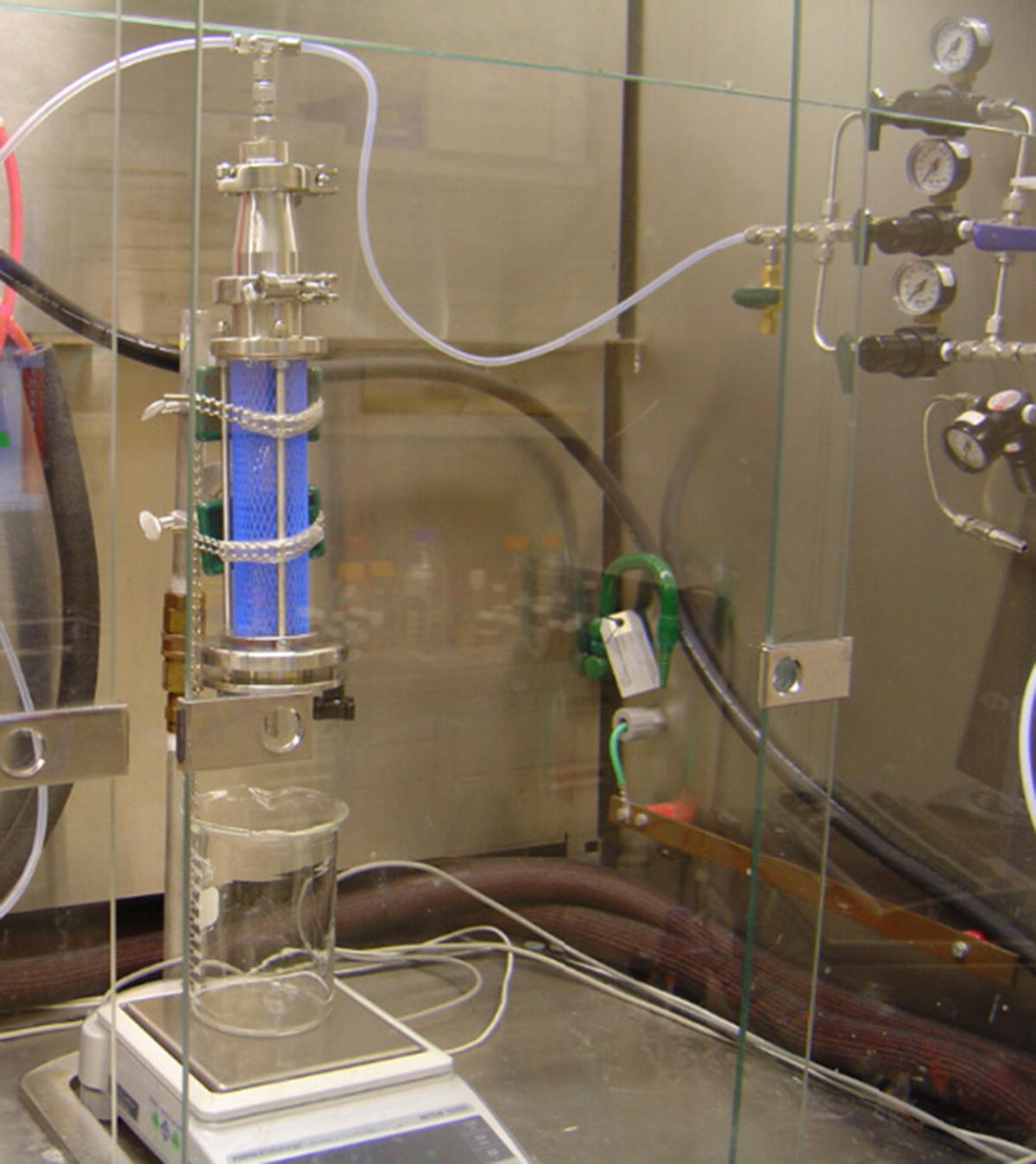
FIGURE 36.1 Standard bench filtration setup where a regulator manifold is used to allow for stepwise pressure modulation during filtration.
The regression is best accomplished through a fitting software either commercially available or with “homegrown” code. One such platform widely used across the pharma industry is DynoChem® software from Scale‐up Systems Ltd. Both the regression and simulation capabilities for this application are available in DynoChem® and were used in the majority of filtration case studies that follow. Regardless of the regression platform, it is important that the number of data points be approximately equal across the different experimental pressures employed to ensure that the regression fit is not biased toward the experimental conditions with the largest number of data points. Alternatively, a proportional weighting could be applied to balance the data sets.
A decision tree (Figure 36.2) was developed to use the filtration characteristics to guide the development strategy and to inform productivity impact from equipment selection during scale‐up or tech transfer. This guide, in conjunction with known logistical and process constraints, is intended to be used as part of the strategy that determines the equipment and processing options.

FIGURE 36.2 Guide for utilization of filtration information.
The case studies that follow begin with the most ideal state, incompressible cake with low resistance, and increase in complexity while highlighting the rationale of the above guidance.
36.3 LOW TO MODERATE CAKE RESISTANCE
In the cases where the resistance is low, average cake resistance (αavg) < 1 × 10¹⁰ m/kg, it is often suitable to move directly to utilization of the characteristic information to simulate the performance of the filtration in the available equipment (Figure 36.3). However, care should be given to ensure the properties of the solid state will not change appreciably upon scaling. The following case demonstrates the scenario when filtration resistance is low and outlines the typical flow of experimentation, characterization, and utilization of the filter cake parameters to simulate filtrations at larger scales to ensure proper selection of equipment and operating parameters.

FIGURE 36.3 Low resistance, low compressibility scenario.
Compound A is crystallized as rod‐shaped particles on the order of 50–100 μm in length and an aspect ratio of about 3 : 10 (Figure 36.4). This slurry is observed to filter rapidly and the particles are not prone to attrition while in the slurry state. From bench‐scale filtration, filtrate mass vs. time data was used to regress a specific cake resistance, media resistance, and compressibility index. The results are shown in Table 36.1, indicating the slurry was suitable for filtration in standard pressure filtration equipment such as an agitated filter dryer (AFD) or an Aurora A‐20 as shown in Figure 36.5. These values were subsequently used to simulate filtration performance, prior to executing in the kilo lab. The case modeled was 1.6 kg of compound A in 28 kg of solvent with a viscosity of 0.777 cP filtered on a filter surface area of 0.05 m2 with a driving force of 14 psi. The simulation predicted a filtration time of 11 minutes, indicating the operation was suitable for the available equipment. This scenario was executed in a kilo lab, and the filtration was completed in 13 minutes, aligning well with the model prediction.

FIGURE 36.4 Microscope image of compound A crystals in slurry.
TABLE 36.1 Filtration Parameters for Compound A
| Scenario | Specific Cake Resistance (α) | Media Resistance (Rm) | Compressibility Index (n) | |
| Bench‐scale data | 1.03 × 10¹⁰ m/kg | 1.81 × 10⁹ 1/m | 0.6323 |

FIGURE 36.5 Aurora filter used in kilo lab.
In this case, since the filtration model performed well across scales, and the process did not present a potential bottleneck upon scale‐up, so no further characterization was deemed necessary. At production scale, the process was run at an 11 kg scale with 242 kg of solvent on a filter surface area of 0.3 m2 under 30 psi. The simulation of this scenario predicted a filtration time of 15 minutes, presenting no concern for long cycle times upon scale‐up. In the manufacturing plant, this filtration required approximately one hour to complete, which was limited by the time required to transfer the slurry from the crystallization vessel to the filter.
36.4 MODERATE TO HIGH CAKE RESISTANCE
In cases where the resistance is moderate to high (αavg ~ 1 × 10¹⁰ – 1 × 10¹³ m/kg) and compressibility is below 1, options to maximize surface area and driving force for pressure filtration or to employ the use of a centrifuge are evaluated. This covers the scenario of Figure 36.6. The same qualifying considerations regarding changes to solid‐state properties persist, but concerns regarding compressibility are more prominent for the cases where higher driving forces.

FIGURE 36.6 Moderate to high resistance, low compressibility scenario.
36.4.1 High Cake Resistance: Optimized Pressure Filtration
Compound B is crystallized as long needles on the order of 20–50 μm in length and an aspect ratio of 10 : 30. This slurry is observed to filter very slowly. The slurry from a bench‐scale experiment (100 g) was filtered and used to regress the specific cake resistance, media resistance, and compressibility index. The results are shown in Table 36.2.
TABLE 36.2 Filtration Parameters for Compound B
| Scenario | Specific Cake Resistance (α) | Media Resistance (Rm) | Compressibility Index (n) |
| From bench‐scale data | 2.44 × 10¹¹ m/kg | 1.54 × 10¹⁰ 1/m | 0.8875 |
These values were subsequently used to simulate filtration rate prior to executing in the kilo lab. The scenario modeled was 1.2 kg of compound B in 18 kg of solvent with a viscosity of 0.437 cP filtered on a filter surface area of 0.05 m2 with a driving force of 14 psi. The simulation predicted a filtration time of 71 minutes. This scenario was executed in a kilo lab and the filtration required 137 minutes to complete.
While the regression of filtration parameters for the bench‐scale data resulted in a good fit, that does not mean that the experiment is necessarily representative of performance on larger scale. This particular crystallization is nucleation dominant and can thus result in a range of particle sizes. Furthermore, the forces imparted on the slurry from mixing can increase with scale, resulting in a different particle size distribution than what is observed on bench scale. The microscope images in Figure 36.7 show that the crystals from the kilo‐scale batch consist of shorter needles with a lower aspect ratio than those obtained in the bench‐scale experiment, resulting in a more dense cake with lower porosity that increased the specific cake resistance to approximately 4.81 × 10¹¹ m/kg. This highlights the importance of repeating the filtration characterization for multiple lots and scales.

FIGURE 36.7 Microscope image of compound B crystals in slurry from lab‐scale experiment (a) and kilo‐scale batch (b).
For scale‐up, this data was used to simulate the filtration at a 16 kg scale with 260 kg of solvent on a filter surface area of 0.3 m2 and a driving force of 30 psi. The simulation predicted a filtration time of 11.4 hours under these conditions. At the manufacturing plant, the filtration required approximately 14 hours per batch, showing reasonable agreement with the model but suggesting that an even higher resistance is obtained for the product slurry. Due to the long filtration time, higher pressures and greater surface areas were explored in order to understand these parameter's sensitivities with respect to cycle time. Due to the high compressibility index, continuing to increase pressure will afford diminishing returns in reducing filtration time. Doubling the driving force pressure to 60 psi (maximum for this vessel) only reduces predicted filtration time to 10.5 hours (8% reduction). Alternatively, using a filter with twice the surface area (0.6 m2) at 30 psi reduces the predicted filtration time to a more manageable 3 hours.
Exploring the equipment and operating ranges to optimize the product filtration can be very valuable in debottlenecking a process. The case described above, using a larger filter surface area, was the best option. For slurries with a high cake resistance, the higher driving force of a centrifuge can also help optimize filtration times and will be discussed in the next case study.
36.4.2 High Cake Resistance: Centrifugation
In cases with higher cake resistances, there is a limitation to overcoming long filtration times with increased surface area and/or pressure differentials. The upper end to the surface area is typically set by the availability of the equipment in the plant. However, additional considerations, like cake washing effectiveness, that are negatively impacted by thin cake heights should also be considered when evaluating this option. The limit to the pressure differential for cakes with compressibilities lower than one is typically set by the equipment specification or the utility capabilities of the production facility. While some Nutsche‐type filters are rated for pressures in the tens of bar, it is more common for pressure filters to be operated with a pressure differential up to 6 bars due to equipment rating and/or available pressure from nitrogen utilities [2]. This driving force is significantly lower than the driving forces that can be applied through the use of a centrifuge. In addition to increased filtrate flux, there are many other considerations that should be included during the equipment selection strategy, which may include deliquoring efficiency, washing efficiency, containment, scheduling, and others.
The following case study exemplifies a typical centrifuge operation for moderate to high cake resistance, where the compressibility is less than one. In this case, an API intermediate was being isolated at a contract manufacturing facility where little characterization of the filtration had been performed. Upon the initial scaling, a long filtration time had been observed. As a response, the vendor split the 45–50 kg batches across two filters to double the filter area in efforts to minimize the filtration time. This was successful to a limited extent, and the resulting filtration time averaged approximately at 16 hours. With a shift in material demand, the batch size needed to be increased to 115 kg. To accommodate this increase in scale, and to improve productivity, a centrifuge was evaluated. To ensure that equipment choice would improve performance, the cake resistance and compressibility were characterized, and equipment information was collected to model and simulate the centrifugation performance. The resistance and compressibility were determined to be 1.2 × 10¹¹ m/kg and 0.9, respectively. The details for the centrifuge surface area, diameter, and rotation speeds were collected and used to simulate the process as seen in Figure 36.8. The results from the simulation suggested that the primary filtration should be complete at approximately 115 minutes, indicating the equipment and operating parameters for the filtration were suitable for the scale increase. The process was subsequently scaled and filtered. The observed filtration time was 125 minutes, in agreement with the model and further demonstrating the value of collecting and using the characteristic data to aid in equipment selection and setting of operation parameters.

FIGURE 36.8 Centrifugation simulation results using DynoChem for 115 kg of product in a slurry, fed in over 30 minutes.
36.4.3 High Cake Resistance: Centrifugation and Compressibility
All of the previous examples have had compressibilities less than one. By examination of the modified Darcy's law (36.1), it can be seen that when a material is incompressible (n = 0), the rate of filtration is linearly proportional to the pressure differential. However, most of the synthetic materials that have been characterized within Amgen's Synthetic Technologies and Engineering labs have ranged from 0.2 to 0.9, in agreement with other commonly reported ranges [3]. Within this range, filtration rate will increase with an increasing driving force, but the proportionality of this relationship diminishes as the compressibility increases. As most materials fall into this low to moderate compressibility range, it is not unreasonable to make this assumption in cases where time or material availability limits the characterization opportunities. This assumption was made for an API intermediate that needed to be rapidly scaled to 3 kg in a kilo lab facility. Due to the limited time and material, cake resistance was measured at a single pressure and determined to be 1.0 × 10¹³ m/kg. The material was assumed to be incompressible, and the filtration was simulated with various equipment to identify a suitable configuration that minimized the filtration time. Using a standard filter in the kilo lab with an area of 0.2 m2 predicted a filtration time of approximately 1690 minutes. As this was not a desirable duration, a centrifuge with a bowl height of 28 cm and a diameter of 40 cm was simulated at 2000 rpm, predicting a filtration time of approximately 85 minutes. The operation was later carried out in a centrifuge with an observed filtration time of 480 minutes, indicating the model was not accurate. The issue causing the slower rate carried into the washing, giving a total filtration and washing and deliquoring duration of approximately 1.5 days. The source of the discrepancy between the model and the observed results was found to be the inaccurate assumption that the cake was incompressible. A retrospective analysis revealed that the cake was highly compressible, resulting in disruptive compression of the cake with increasing driving force. As with all filtrations, particles will stack on top of each other to form the cake. However during filtration with this type of compression, the particles will break under the higher compressive forces and will collapse to fill in void spaces within the cake as illustrated in Figure 36.9. As this is an irreversible process, it leads to higher cake resistance across the pressure range, having an impact to the subsequent washing and deliquoring operations. For this case, breakage was confirmed by image analysis of the particles before and after centrifugation. Analysis of filtration performance for the material revealed that cake has a compressibility greater than or equal to 1.15. In the regime of compressibility greater than or equal to 1.0, it is possible to increase the driving force to an extent where the filtration rate starts to decrease as pressure is further increased. In this example, if the compressibility of 1.15 had been used to simulate the centrifugation, it would have resulted in a predicted filtration time of 500 minutes. Further, the model would have shown a more optimal rotation speed of 600 rpm would have further decreased the filtration time to approximately 270 minutes. In addition to the value of incorporating compressibility into the filtration characterization, this case also highlights the need to ensure that filtration characterization is completed over a pressure range that covers the driving forces that will be used during production.
FIGURE 36.9 Disruptive deformation of a cake: particles break under increased forces and rearrange to fill the interstitial space between particles, resulting in a smaller void fraction and observed increase in cake resistance.
36.5 REDESIGN OF SOLID‐STATE PROPERTIES FOR IMPROVED FILTRATION
In cases where the resistance or the compressibility of the cake is high, it may not be feasible to achieve a desirable filtration rate via equipment selection or modifications to the operating parameters. When presented with this scenario, it is advantageous to evaluate modifications to the process that alter the solid‐state properties of the material being isolated (Figure 36.10).
FIGURE 36.10 High resistance and/or high compressibility scenario.
During the scale‐up of an early phase API intermediate an unexpectedly long filtration was reported, taking 22 hours to isolate 44.5 kg on a standard pressure filter using a pressure differential of approximately 1 bar. Isolated material from the filtration was collected for characterization (Figure 36.11). The cake resistance was found to be 6.0 × 10¹⁴ m/kg. Simulation of the filtration with this resistance predicted a 23.5 hour filtration, in good agreement with the observed filtration time. This material was significantly smaller than that typically observed during development, which had an average cake resistance of 1.5 × 10¹¹ m/kg. Both materials had a compressibility well below one. Given the low compressibility and similar pressure differentials used for both scales, the difference in particle sizes cannot be attributed to breakage during filtration. A number of factors were evaluated to identify the root cause of the smaller particles. A mixing experiment revealed an attrition sensitivity of the solids, both during the crystallization and while aging the final slurry. The sensitivity was first identified in an experiment where a representative slurry is mixed in a standardized 1 L vessel and monitored with FBRM. Mixing is increased from a baseline agitation speed to an elevated speed where it is held for at least one hour and then returned back to the baseline agitation speed. The speed is increased in a stepwise manner, and the cord length distributions from each baseline are compared to observe any changes as the mixing forces are increased. The procedure revealed significant attrition as mixing forces were increased, as seen in Figure 36.12. This highlights the importance of completing studies of this nature to ensure that the materials being used to characterize the filtration are truly representative of the range of particles that will be achieved through the crystallization and scaling.
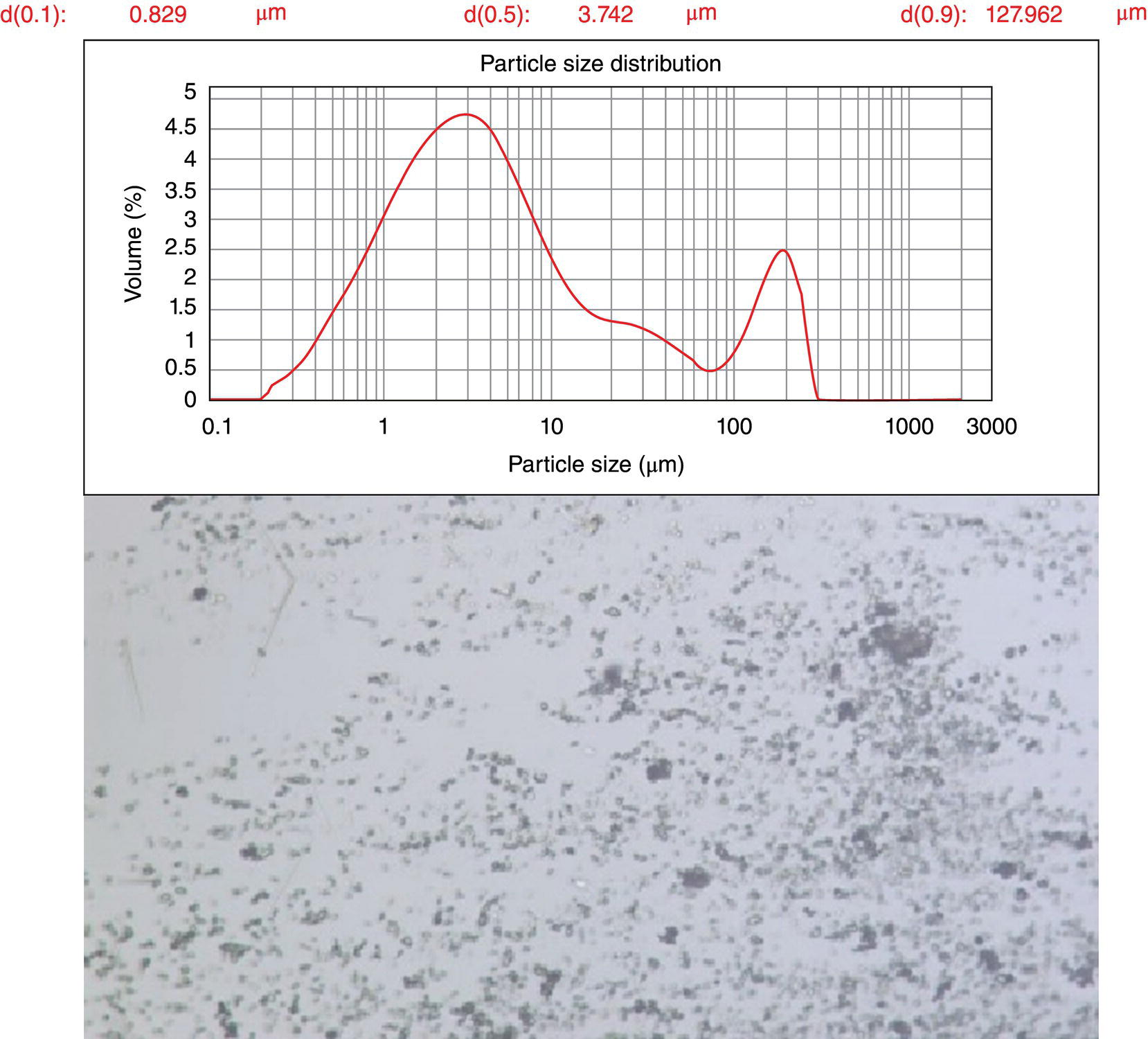
FIGURE 36.11 Particle size distribution and microscope image of the API intermediate with unexpectedly long filtration.

FIGURE 36.12 FBRM trends and shift of cord length distributions show appreciable attrition as agitation is increased in a 1 L vessel. Microscope images of crystallization performed at 300, 600, and 800 rpm in the same vessel.
As the attrition of the particles leads to higher cake resistance and mixing forces are expected to increase with scale, prolonged filtration may not be easily resolved with changes to filter type, size, or driving force. Instead, to mitigate the issue, efforts were applied to change the solid‐state properties of the material. The investigation focused on solvents known to be advantageous to the upstream reaction, where the solvent type and ratios were varied to investigate the impact to habit or form. While slightly different sizes could be obtained from some of the combinations, all materials of this form exhibited similar propensity for attrition. However, an alternative polymorph (Form II) was identified in a water, isopropyl alcohol solvent system that exhibited a different habit with improved filtration and resistance to attrition. A comparison of the habit and solubility of the two forms is shown in Figure 36.13. Form II had a cake resistance of 3 × 10⁹ m/kg and no notable propensity for attrition under relevant mixing conditions, alleviating the prolonged filtrations.
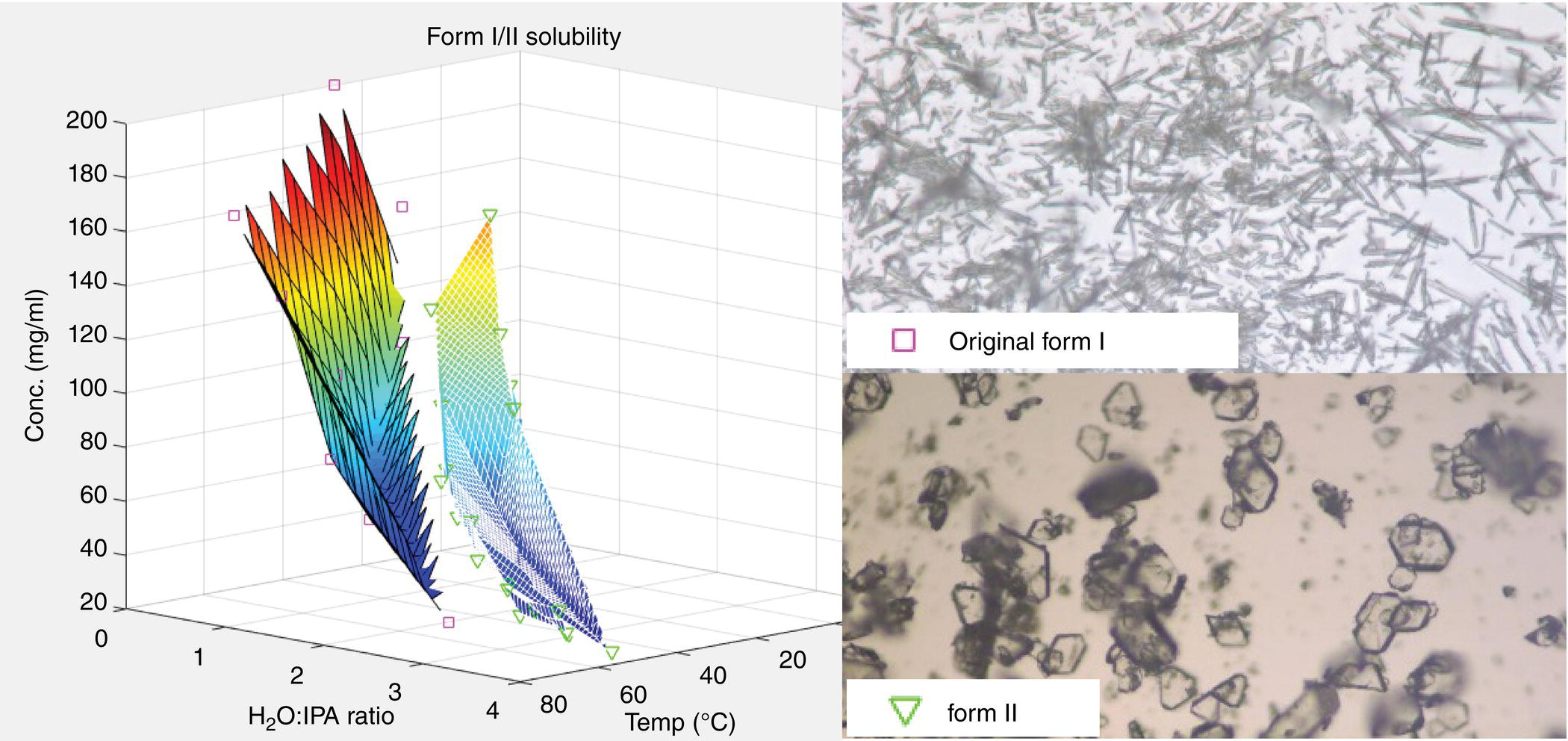
FIGURE 36.13 Solubility plots of the monotropic forms in the solvent system used to isolate Form II, where the Form I plot is on the left and Form II on the right. Form I has a melting point of 150 °C and Form II has a melting point of 170 °C.
Ideally, problematic characteristics of the cake are identified early in the process development cycle such that there is ample time to investigate modification to the material's solid‐state properties to improve the filtration. In the previous example, a change to the crystal form was the means to modify the solid‐state properties. Other common practices include changes to the supersaturation profile during crystallization to achieve larger or more uniform PSDs, heat cycling to remove fines, modifications of solvent/cosolvent system to promote a different form or habit, or changes to purity profiles that impact the particle aspect ratios.
36.6 CUMULATIVE PLUGGING OF AGITATED FILTER DRYER PLATE
During process development of a compound with prismatic habit, lab pressure filtrations of a crystal slurry were performed to measure the flow resistance of the incompressible wet cake. A low resistance of approximately 106 m/kg was measured indicating a rapidly filtering cake. Filtrations and cake washes performed in the pilot plant using AFDs and Nutsche filters were also fairly rapid. Between batches, the AFD was cleaned per standard pilot plant practice. The Nutsche filters, shown in Figure 36.14, have a perforated bottom support plate and were lined with polymeric filter cloth. The polymeric filter cloth used in the Nutsche filter is removed and discarded after each batch and replaced with a new filter cloth.

FIGURE 36.14 Side and top views of an open Nutsche filter.
Due to the good filtration properties of the compound – including absence of cake cracking – observed during pilot plant batches, filtration received modest attention during process scale‐up and transfer to the production site. The initial sets of batches at the production site consisted of three campaigns of 2, 2, and 5 batches. Production batches of a given compound are frequently campaigned for efficiency to minimize equipment cleaning time. Inter‐batch cleaning within a campaign consisted of cleaning the reactors but not the AFD. Inter‐batch cleaning of the AFD would reduce the yield of each batch. A thorough cleaning of the entire equipment train (including AFD) is performed at the end of each campaign.
When an AFD is unloaded, nearly all of the dried compound is removed from the AFD by the action of the blade; in some cases a rake‐like instrument may be used to manually remove additional dried solids. However, a thin heel of dry solids typically remains on the AFD filter plate below the bottom of the blade. This thin layer may be partially compressed or attrited – resulting in additional flow resistance in subsequent batches of the campaign. In addition, cumulative plugging of the AFD filter plate can occur during the campaign; this results from penetration of fines into the filter plate with each batch.
After the crystal slurry is filtered in the AFD, the cake is displacement washed with two equal portions of wash. This is followed by a two hours nitrogen blow to deliquor the cake and then vacuum drying. The production site filtration receiver (unlike the pilot plant receiver) had a level sensor enabling accurate measurement of filtration and cake wash rates. Filtration rates for the crystal slurry filtration and two displacement cake washes appear in Table 36.3 for the nine batches, which were of the same batch size. The filtration rate decreases over the course of each campaign for all three campaigns. For example, in campaign 2, the batch 2 filtration rate was 70% less than the batch 1 rate. This reduction in filtration rate increased the overall processing time.
TABLE 36.3 Production‐Scale AFD Filtration Rates
| Campaign 1 | Campaign 2 | Campaign 3 | |||||||
| Batch 1 Rate (cm/min) | Batch 2 Rate (cm/min) | Batch 1 Rate (cm/min) | Batch 2 Rate (cm/min) | Batch 1 Rate (cm/min) | Batch 2 Rate (cm/min) | Batch 3 Rate (cm/min) | Batch 4 Rate (cm/min) | Batch 5 Rate (cm/min) | |
| Filtration of crystal slurry | 15.6 | 7.0 | 12.9 | 3.0 | 13.8 | 9.1 | 6.4 | 1.9 | 1.7 |
| Filtration of Wash #1 | 7.2 | 0.9 | 13.4 | 3.4 | 12.8 | 8.7 | 7.1 | 0.7 | 2.2 |
| Filtration of Wash #2 | 7.8 | 1.3 | 6.2 | 2.7 | 7.0 | 4.1 | 3.7 | 1.8 | 1.5 |
Expressed as superficial linear velocity of the filtrate.
The cumulative filter plate plugging impacted downstream processing. After completion of cake washing, pressurized nitrogen is applied to the AFD headspace for two hours to fully deliquor the cake by flowing the nitrogen through the cake and out the bottom AFD discharge port. The bottom AFD outlet is vented at atmospheric pressure. This deliquoring reduces the wet cake residual solvent content from 30 to ~10 wt %. Regions of wet cake above partially plugged portions of the filter plate were less effectively deliquored by nitrogen flow. This increased the burden on the subsequent heated vacuum drying step.
In the vacuum drying step, the AFD jacket is heated, and full vacuum is applied to the bottom AFD outlet port. A slight flow of N2 is applied to the AFD headspace for convective transport of solvent vapor through the cake. The transition from the positive pressure of the N2 blowdown to vacuum for heated drying in the upper AFD chamber typically takes about five minutes as shown in the process trend in Figure 36.15. This was the case for the first batch of the campaign. However, due to the cumulative partial plugging of the filter plate, it took three hours in the fourth batch (in campaign 3) to remove the N2 in the AFD headspace through the filter plate to the fully evacuated bottom chamber of the AFD.

FIGURE 36.15 Trends of the upper AFD chamber pressure (barg) for batches 1 and 4 during the switch from the positive pressure of the N2 blowdown to vacuum heated drying. The two trends have different time scales on the x‐axis.
Over the course of the heated vacuum drying, the cake in the AFD was sampled for residual solvent analysis. The residual solvent concentration of the first sample of cake (taken at the start of drying when the dryer reached temperature) increased over the course of the campaign (see Figure 36.16). Similarly, the required drying time increased during the campaign. The fifth batch took twice as long as the first batch to meet the residual solvent specification.
FIGURE 36.16 Concentration of residual solvent (log scale) in the wet cake during the course of drying.
Increased operational efficiency can be achieved by monitoring cumulative filter plate plugging. During a campaign of batches, one approach to monitor cumulative AFD plate plugging is to measure the combined resistance of the heel layer and filter plate in the emptied AFD using a stream of nitrogen. This can be performed during the pressure check of the AFD that precedes each batch. The combined resistance should be no more than about 25% of the expected cake resistance. This corresponds to a combined plate–heel resistance of approximately 1E+11 1/m (for the case of a 30 cm tall cake bed). For example, when 100 SCFH of N2 is applied to an AFD with a plate area of 1.0 m2 (with discharge at atmospheric pressure), the pressure drop should not exceed 0.15 psi. If substantial filter plate plugging/heel resistance is detected, then a cleaning should be performed to remove the heel as well as solids embedded in the filter plate. If the filter cake becomes compressed or the filter plate becomes plugged during the processing of a batch, then one option to accelerate drying is to pull vacuum from the AFD headspace during the drying.
REFERENCES
- 1. Murugesan, S., Hallow, D.M., Vernille, J.P. et al. (2012). Lean filtration: approaches for the estimation of cake properties. Org. Process Res. Dev. 16: 42–48.
- 2. Palosaari, S., Louhi‐Kultanen, M., and Sha, Z. (2015). Industrial crystallization. In: Handbook of Industrial Drying, 4e (ed. A.S. Mujumdar), 1286–1287. Boca Raton, FL: CRC Press.
- 3. Murugesan, S., Sharma, P.K., and Tabora, J.E. (2010). Design of filtration and drying operations. In: Chemical Engineering in the Pharmaceutical Industry: R&D to Manufacturing (ed. D. am Ende), 317. Hoboken, NJ: Wiley.