
Wireless Power Transfer
Mohammad Etemadrezaei North Carolina State University, Raleigh, NC, United States
Abstract
This chapter covers different methods of wireless power transfer (WPT) with the main focus on weakly coupled inductive WPT systems. Such systems are increasingly getting popular due to the advantages they bring compared with wired power transfer. A typical two-coil inductive WPT system is analyzed, and the system parameters such as magnetic link efficiency are derived. Various WPT resonance topologies for both primary (transmitter) and secondary (receiver) coils are reviewed. Main elements of the system including high-frequency (MHz region) inverters such as class-D and class-E are explained. The WPT systems with multiple coils in primary, secondary, or in between them are covered. And the effects of coil size, shape, and alignment on the link efficiency are studied. The chapter concludes by exploring various coil components such as winding type, ferrite pad, and metal shielding plate for high-frequency and high-quality-factor coils.
Keywords
Wireless power transfer (WPT); Inductive power transfer (IPT); Resonance; Magnetic link efficiency; Weakly coupled systems; Loosely coupled systems; Quality factor; Coupling factor; Misalignment; Class-D and class-E inverters
22.1 Introduction
Wireless power transfer (WPT), in its general term, has been around us for decades in applications such as telemetry, satellite communications, and radio frequency identification (RFID) tags. Most of these applications transfer low amounts of power, in the range of microwatts to milliwatts, for data transfer. For higher-power applications, from few watts to several kilowatts, over moderate distances, the WPT has recently been the focus of the industrial developments. The most common method of high power WPT is through inductive coupling that was invented by Nikola Tesla more than a century ago. The recent developments in semiconductor industry for high frequency and high-power applications have paved the path for high-power inductive WPT improvements. Inductive WPT offers several benefits over the wired connection and is applied in numerous applications such as wearable electronics, health care, and automotive industry. This chapter starts by reviewing various methods of WPT, followed by the design and analysis of inductive WPT. The overall inductive WPT is studied step by step and component by component; therefore, it is recommended to refer to the references for detailed analysis and information.
22.2 Methods of Wireless Power Transfer
There are different methods to wirelessly transfer power between a source and a receiver. Each method has its own characteristics that are useful for certain applications. Here, the most common methods of wireless power transfer are briefly discussed.
Radio frequency waves. Radio frequency (RF) is the most common way of transmitting data as the waves can propagate through vacuum (Fig. 22.1A). RF waves can also be used to transmit power such as in microwave oven and in RF heater and welding machines. The operating principle of RF transmitting and receiving antennas is based on the interaction of electric and magnetic inductions determined by the full set of Maxwell's equations [1].

Optical link. Optical links use the light—in the ultraviolet, visible, and infrared regions of electromagnetic frequency spectrum—to transfer energy between source and receiver over long distances (Fig. 22.1B). The light-emitting source can be sun or power laser diodes for high power delivery and LED for data transmission [2]. The receiver unit is a light-sensitive device such as photovoltaic converter, solar cell, or photodiode. The optical link can be free space, air, fiber optics (it can be considered a wireless link due to the absence of conductive materials), etc. Although the optical links have been mostly used for data transmission, higher power in the form of solar and laser can also be transmitted [3]. One application is laser power transfer through optical fiber that has the advantage of electric isolation between the source and receiver.
Ultrasound. Ultrasonic waves propagate in a physical medium such as air, water, metal pipe, human tissue, etc., by exchanging in between kinetic and potential energies inside the medium (Fig. 22.1C). The ultrasound frequency is above the hearing limit of humans, about 20 kHz, and goes up to several megahertz. The ultrasound power delivery has been mostly applied in low power data transmission, nondestructive testing, remote sensing, and navigation systems [4]; however, higher power transfer for biomedical implants and consumer electronics has gained notable attention recently [5]. The ultrasound wave can be converted to electricity and vice versa, using piezoelectric crystal [6]. One of the advantages of ultrasound power delivery is the ability to travel long distances (depending on the attenuation in the link medium) and through the nontraditional curved power paths. In addition, the low propagation speed of ultrasound wave leads to a more achievable design of directional transceivers compared with RF waves.
Capacitive power transfer. Capacitive power transfer (CPT) uses time-varying electric field between capacitor electrodes to transfer power wirelessly (Fig. 22.1D). The coupling capacitance and the transferred power are limited to the available area and the minimum distance between the electrodes. The CPT has mostly been applied to low power and data transmission systems such as in biomedical implants, bioinstruments, integrated circuits, and the isolated power supply due to galvanic isolation of the source and receiver. The CPT can be implemented in different circuit topologies such as resonance to achieve higher power transfer with increased efficiency [7].
Inductive power transfer. Inductive power transfer (IPT) uses time-varying magnetic field between mutually coupled coils to transfer power wirelessly. As the amount of transferred power depends on the mutual coupling between the coils, IPT systems are divided into two categories, namely loosely and tightly coupled systems. In the tightly coupled systems, the coupling factor (coupling coefficient) is close to unity; therefore, the transferred power efficiency is quite high. A well-known application for tightly coupled systems is a power transformer (Fig. 22.1E). In loosely or weakly coupled systems, the coupling factor is quite low; depending on the application, it can range between 0.01 and 0.5. The main reasons for the low coupling coefficient are the large distance between the coupled coils compared with the coil sizes and/or the absence of high permeable magnetic path connecting them. The low coupling coefficient reduces the power transfer efficiency; therefore, the receiving coil needs to be resonated to increase the efficiency. This chapter is mainly focused on loosely coupled inductive WPT systems (Fig. 22.1F).
22.3 Inductive WPT System Applications
Inductive WPT systems are increasingly getting popular in applications where (a) the flexibility of relative movement between source and load is an advantage, (b) there is limited space for energy storage elements in the load, (c) there is limited access to the load side, and (d) cordless connection improves safety. Some applications that use inductive WPT include the following:
Consumer electronics. As the power density and usage of consumer electronic devices such as notebook, smartphone, and wearables keep increasing, the wireless power connection to the device is a significant advantage. The WPT in consumer electronics is a fast pace industry, and with several standards already in place, the time from product development to the market is short compared with health care and automotive sectors.
Health care. As medical therapies are getting more dependent on implantable electronics, WPT becomes a promising technology in health-care devices [8]. One such application is ventricular assist device (VAD) that circulates the blood inside the body as a pump. The use of inductive WPT eliminates the wire connection between the power source (outside the body) and the VAD (inside the body) [9], which is beneficial to the patient in many aspects.
Another benefit of WPT in electronic implants is the possible reduction or elimination of energy storage element in the implant. This leads to smaller size and lighter weight electronics that brings comfort to the patient. It also reduces the costs and risks associated with the replacement of the energy storage device inside the body. One such application is in retinal implants with the WPT device powering a chip implanted in the eye that (partially) restores vision to the patients with specific retinal diseases.
Electric vehicles. Wireless inductive charging for electric vehicles (EVs) is a step forward toward the mainstream adaptation of EVs as the main transportation systems. The EVs can get the wireless power while in motion (dynamic charging) [10] or in parked position (stationary charging). The dynamic charging can be applied by implementing numerous transmitter coils along the driving path, all connected to each other in parallel and fed by a single source [11]. This is currently most applicable for EVs with predetermined driving path such as electric busses. In the stationary charging, the EV gets the wireless power by having the receiver and transmitter coils aligned and stationary. Since a slight misalignment of the coils would drop the efficiency, specific coil arrangements or multiple coils can be used to make the WPT more tolerant to misalignment [12].
22.4 Resonant Inductive WPT System Design
22.4.1 System Components
Fig. 22.2 shows an inductive WPT system block diagram. The power source feeding the WPT system typically consists of AC-DC-AC (rectification-inversion) stages. The transmitter coil can be compensated to increase the overall system efficiency and reduce the volt-ampere rating of power source. However, this compensation (assuming loss-less) does not affect the magnetic link efficiency, ηlink, defined from power source output up to the receiver rectification.

The power is transmitted from the source coil (transmitter) to the load coil (receiver) using Faraday's law of induction. Having the two mutually coupled coils, the higher the coupling coefficient between them, the higher the power transfer efficiency. The transmitter and receiver coils can be made up of various components. Magnetic core can be used to shape the flux path, increase the inductance, and enhance the coupling. Metallic shields can be used to reduce the high frequency magnetic fields around the system and reduce the electromagnetic interference (EMI). However, there will be eddy current losses inside the coil conductor and the metallic shield in addition to the magnetic core losses, which bring up the significance of efficient coil design in WPT systems. The high quality factor and highly coupled coils will be discussed in more details later in the chapter.
The wireless power is delivered to the load through the receiver coil, reactive compensation, and electronic rectification for DC loads. The link efficiency depends on the receiver coil compensation and the value of load resistance. The feedback control electronic sensors are used in order to operate the WPT system reliably and efficiently.
22.4.2 Operating Field Region
The electromagnetic power transfer is based on Maxwell's equations. For a coil used in WPT system, the governing Maxwell's equations would have exact or simplified formats depending on the coil material, operating frequency, and the power transfer distance, leading the system to operate in one of the three near, Fresnel, or far-field regions [1] (Fig. 22.3). In the near-field region, the reactive energy storage is dominant, and there is negligible radiative power transfer. The transition from near-field in to far-field is through the Fresnel region where the reactive energy storage is still dominant but the coil has radiation patterns. At distances far from the coil, the system operation is in the far-field region where the coil has radiation patterns and the power is transmitted through radiation resistance, for example, RF WPT. In the far-field region, the coil electromagnetic fields are based on the exact set of Maxwell's equations.

For coils (antennas) much smaller than the electromagnetic wavelength λ, the transition happens from the near-field in to far-field, and the Frensel region may not exist. This boundary is typically defined at the distance λ/2π from the coil. In the inductive WPT systems focused in this chapter, the frequency and the distance between the transmitter and receiver coils are small enough (up to several megahertz in frequency and from several millimeters to few meters in distance) for the system to remain in the near-field region.
22.4.3 Efficiency Equations
There are different methods for the analysis of inductive WPT systems depending on the complexity of the system and accuracy of the analysis. The most accurate method is mesh theory that uses the resistance, inductance, and capacitance matrices to solve for the voltage and current in the system: ![]() . This method is beneficial for systems with multiple coils (including transmitter, receiver, or repeaters), as the inductance matrix contains the self and mutual inductances for all the coils. The mutual capacitance (capacitive coupling) between the coils is neglected in inductive WPT systems, and the capacitance matrix is a diagonal matrix with compensating capacitors as the diagonal elements of that matrix.
. This method is beneficial for systems with multiple coils (including transmitter, receiver, or repeaters), as the inductance matrix contains the self and mutual inductances for all the coils. The mutual capacitance (capacitive coupling) between the coils is neglected in inductive WPT systems, and the capacitance matrix is a diagonal matrix with compensating capacitors as the diagonal elements of that matrix.
The other method is based on the impedance reflection and is useful for simple WPT systems such as a two-coil system (can be modified to single transmitter/receiver system with repeaters/resonators in between). The advantage of this method is the ability to derive closed-form formulas for different variables such as voltage gain, input/output impedances, and link/system efficiencies. The focus of this section is on a typical two-coil inductive WPT system. Fig. 22.4 shows the equivalent circuit of the two-coil WPT system. The power dissipations inside the remote electronics, rectifier, regulator, and the load are included in the equivalent AC load RL.

In the WPT system, the amount of impedance seen by the power source inverter is a key parameter that directly contributes to the inverter, link, and system efficiencies, along with voltage gain and maximum wireless power transfer. In order to find this impedance, all the impedances in the secondary side need to be reflected to the primary side. In a two mutually coupled coils with mutual inductance of M, the reflected impedance to the primary side is ![]() in which Z2 is the total impedance in the secondary coil,
in which Z2 is the total impedance in the secondary coil, ![]() . When the secondary side is resonant at
. When the secondary side is resonant at ![]() (Z2 is real), the reflective impedance to the primary side is pure resistive and is defined by
(Z2 is real), the reflective impedance to the primary side is pure resistive and is defined by

In the Eq. (22.1), k is the coupling coefficient between the primary and secondary coils, and R1 and Q1 are the primary coil resistance and quality factor, respectively. And QL is the secondary coil load quality factor that is defined by ![]() . Using the reflected impedance approach, the link efficiency is then defined by
. Using the reflected impedance approach, the link efficiency is then defined by

Eq. (22.2) is valid for both resonant and nonresonant secondary coils. In order to increase the link efficiency, the transmitter side efficiency that is the first term in Eq. (22.2) needs to be maximized by increasing the reflected resistance. As the reflected resistance is limited by the low coupling factor in weakly coupled inductive systems, resonating the secondary tank helps increasing the reflected resistance. This is the main reason to resonate the secondary side to increase the link efficiency.
There are three common optimization objectives for inductive WPT system design [13]. First, increasing the link efficiency that is the objective used in this chapter. Second, desensitizing the link gain versus coupling factor k variations. For example, in a bell-shaped link gain versus k, the maximum gain that corresponds to kcritical has the least sensitivity to k variations. The disadvantage of this method is that the theoretical limit for the link efficiency is reduced. Third, stagger tuning that is the combination of the first two objectives to have higher limits for link efficiency while the link gain is not very sensitive to coupling factor changes.
The two-coil inductive WPT system, in its basic configuration, can have six different compensation topologies depending on the type of resonance in the primary and secondary coils (Fig. 22.5). The secondary coil is assumed to be resonated at ![]() in series or parallel. The series-resonant secondary has current output type and is suitable for small values of RL. The parallel-resonant secondary, in the other hand, has voltage output type and is suitable for large loads. The advantage of parallel-resonant secondary is that the coil parasitic capacitance can be included in the compensating capacitor in parallel. The disadvantage of parallel resonance is that resonant frequency depends on the value of RL.
in series or parallel. The series-resonant secondary has current output type and is suitable for small values of RL. The parallel-resonant secondary, in the other hand, has voltage output type and is suitable for large loads. The advantage of parallel-resonant secondary is that the coil parasitic capacitance can be included in the compensating capacitor in parallel. The disadvantage of parallel resonance is that resonant frequency depends on the value of RL.

The primary coil can be resonated (series or parallel) or nonresonated as it does not affect the link efficiency ηlink. The series-resonant primary requires high-current and low-voltage output from the switched-mode power supply FETs, while the parallel resonant requires high-voltage and low-current output. High values of current increase the FET driver losses, and high voltages increase the FET capacitive losses. A combination of series- and parallel-resonant primary coil can be implemented to operate the system at high efficiencies[13]. Fig. 22.5 shows the different primary and secondary compensation topologies. In all these topologies, the system operating frequency is at ![]() . The power supply output may not be pure sinusoidal; however, the power is transferred to the secondary only at fundamental frequency f0. The other harmonics do not contribute to power transfer, but they increase the losses in the primary side.
. The power supply output may not be pure sinusoidal; however, the power is transferred to the secondary only at fundamental frequency f0. The other harmonics do not contribute to power transfer, but they increase the losses in the primary side.
Table 22.1 shows a summary of the key system parameters for a two-coil WPT system including the resonance frequency, reflected impedance to the primary side, load quality and dissipation factors, and link efficiency. Not to mention that the above-mentioned parameters do not depend on the primary coil compensation topology. In addition, the maximum link efficiency has the same equation for both the series- and parallel-resonant secondary coil.
Table 22.1
Inductive WPT system parameters for series- and parallel-resonant secondary
| Secondary compensation | Series resonant | Parallel resonant |
| Resonance frequency | ||
| Load quality (Q)/dissipation (D) factors | ||
| Reflected resistance to primary | ||
| Reflected reactance to primary | ||
| Load factor | ||
| Link efficiency |  |
|
| Maximum link efficiency |  |
|
It is observed from the Table 22.1 that the link efficiency ηlink is a function of load factor α and k2Q1Q2; and, ![]() is only a function of k2Q1Q2. Fig. 22.6 shows the link efficiency of a two-coil inductive WPT system with a resonant (series or parallel) secondary side. For a fixed k2Q1Q2, there is a load factor α that maximizes the link efficiency. The maximum link efficiency increases by increasing k2Q1Q2, meaning that in inductive WPT systems, increasing not only the coupling factor but also the coil quality factors boost the efficiency.
is only a function of k2Q1Q2. Fig. 22.6 shows the link efficiency of a two-coil inductive WPT system with a resonant (series or parallel) secondary side. For a fixed k2Q1Q2, there is a load factor α that maximizes the link efficiency. The maximum link efficiency increases by increasing k2Q1Q2, meaning that in inductive WPT systems, increasing not only the coupling factor but also the coil quality factors boost the efficiency.

In inductive WPT systems, the coupling factor is typically small, that is, in the range of 0.01–0.5. The low coupling factor leads to small values of impedance being reflected to the primary side. This brings the power supply close to unloaded operation mode at which its dissipation dominates the total power dissipated in the primary coil and transferred to the secondary side. Therefore, in loosely coupled systems, it is essential to optimize for the whole system efficiency by including the power supply, magnetic link, and also secondary side remote electronics.
22.5 WPT Systems With Multiple Coils
In WPT systems, there can be multiple coils in the transmitter, receiver, or in between them that help extend the use of WPT to practical applications. Here, the most common types of multiple-coil inductive WPT systems are reviewed, discussing their applications, (dis)advantages, and challenges.
22.5.1 Single Transmitter and Receiver With Multiple Coils in Between
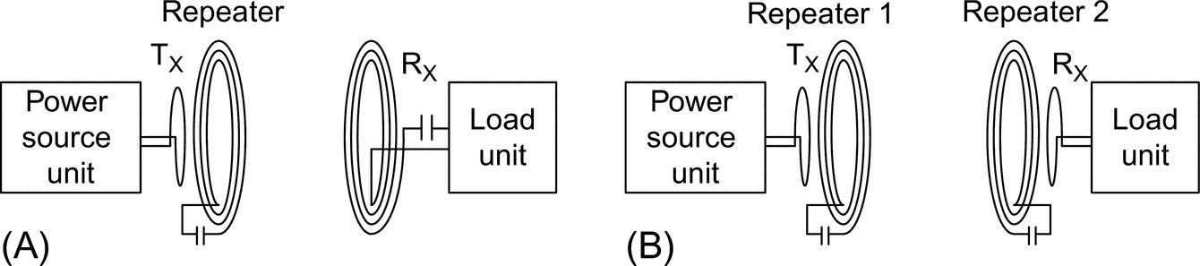
The single transmitter and receiver WPT structure can include one, two, or more repeaters (resonators) in between. There are different applications that implement such structures. One application is to transmit power to large distances using repeaters along the path or even transmit power along a curved path. The other application is to have the repeater tightly coupled to either the transmitter or the receiver [14] (three-coil WPT, Fig. 22.7A), similarly, two repeaters in a four-coil WPT [15] (Fig. 22.7B). There are two main reasons for such configurations: (a) to have more degrees of freedom to maximize the efficiency and desensitize the link gain versus coupling factor without scarifying one objective for the other as was discussed earlier in the chapter and (b) to have the highly coupled transmitter-repeater or repeater-receiver coils act as practical and efficient impedance matching elements in both the source and load sides.
22.5.2 Multiple Transmitters and Single Receiver
The applications that implement multiple transmitter coils and a single receiver are mainly classified into two areas, one is dynamic WPT and the other is misalignment tolerant systems. The dynamic WPT systems transfer the power wirelessly while the receiver is in motion. A known example is EV dynamic charging in which multiple transmitter coils are placed along the driving path and the receiver coil is placed in the moving vehicle. The challenge of such systems is to efficiently power the transmitter coils. A simple method is to have a power supply for each transmitter, and the power is transferred to the receiver by sensing it when it is aligned to it. The drawback of this method is the use of numerous power supplies. The other method is to have a long transmitter pad along the vehicle driving path. The disadvantage of this method is that only a portion of the coil transmits power while all of it is dissipating power. A way to solve these problems is to have multiple transmitters coils connected in parallel to one power supply. The current flows in a coil that is aligned with the receiver coil using reflected impedance while there is no current flowing in the other transmitter coils [11] (Fig. 22.8).

The other application with multiple transmitter coils is to have a misalignment tolerant system. As the coupling (and so the efficiency) of a two mutually coupled coils drops sharply by a slight misalignment between them, implementing multiple transmitter coils can increase this tolerance [12]. Multiple transmitter coils can also be used to provide a uniform magnetic field across a surface area giving the receiver the freedom of movement over that area [16].
22.5.3 Single Transmitter and Multiple Receivers
In some WPT applications, multiple receivers need to get the power simultaneously from a single transmitter pad (Fig. 22.9). The amount of power transferred to each receiver is linearly related to the resistance it reflects to the transmitter. In such systems, the first challenge is that the change of power transfer to one receiver could affect the amount of power transfer to other receivers. To avoid this, constant-current-flow topologies such as LCL in the transmitter coil are required.

With the transmitter coil having a constant current, power sharing to the receivers can be implemented using dynamic (active) tuning in each receiver side. The dynamic tuning can be implemented using L-C network [17], standard boost [18], or tristate boost [19]. In the L-C network method, a discrete matrix of L and C components is actively switched to control the reflected impedance to the transmitter side. The standard boost method controls the active power transfer to the receiver by changing the reflected resistance to the transmitter coil. Similarly, the tristate boost controls the active power flow, but also, the reactive power flow to the receiver can be controlled in case of detuning. The tristate boost has an extra degree of freedom compared with standard boost by shorting the inductive energy in boost (freewheeling).
One of the challenges in multiple-receiver WPT systems is the magnetic cross coupling between the receivers when they are in close proximity to each other (Fig. 22.9). The cross coupling would change the expected power transfer to the receivers and impose system performance issues. One method to reduce the cross coupling is to use multiresonant WPT system in which each receiver is resonant at one of the transmitter carrier frequencies [20].
22.6 A Glance Into WPT Power Source Converter
In weakly coupled inductive powering applications, the design of transmitter coil power converter is directly linked to magnetic link design and therefore needs to be part of the whole WPT system optimization. The main reason is due to the weak coupling, as the amount of reflected resistance to the transmitter coil is quite small, the converter operates close to freewheeling. And large amount of current is needed to flow in the coil to generate the required magnetic field and power.
The choice of transmitter coil power converter depends on the WPT application, power level, and operating frequency. For example, in EVs, the amount of power required to wirelessly charge the battery can range from 3.3 kW up to several tens of kilowatts, with frequency ranges from 20 kHz up to few hundreds of kilohertz. For such power and frequency levels, highly efficient AC-AC power converters such as full-bridge AC-DC rectifier and DC-AC inverter can be used to drive the transmitter coil. These power converters have been well stablished in the past few decades in terms of efficiency, reliability, and cost.
An important benefit of inductive WPT is in applications with small size and medium to high power requirements. As the magnetic link size reduces, the reflected resistance to the transmitter coil gets reduced as well. To compensate for this reduction, the operating frequency needs to increase to keep the power level up. For example, in electronic devices such as phones, wearables, and laptops, the power rating can range from 1 W up to about few hundred watts. For inductive WPT in the megahertz frequency region, the operating frequency is typically bound to industrial, scientific, and medical (ISM) band of 6.78, 13.56 MHz, and so on. The power converter design in the megahertz region is critical as the dynamic losses increase in the FETs. There are several typically used DC-AC power inverters in the megahertz frequency range such as classes A, B, AB, C, D (ZCS and ZVS), and E. In this section, the focus is on switched-mode class-D and class-E power inverters as they deliver highest efficiencies of all the classes [21,22].
22.6.1 Class-D Inverter
Class-D inverter has a voltage output characteristic that is good to feed series-resonant transmitter coil. The resonance is not a critical requirement for class-D inverter although it increases the current for a fixed voltage. And the inverter can power resistive, inductive, and capacitive loads [23]. Fig. 22.10 shows the schematic of the class-D inverter with ideal waveforms. At resonance, the impedance seen by the inverter is the transmitter coil resistance R1, in addition to the reflected resistance from the receiver side Rref. In weakly coupled WPT systems, the Rref is very small and can bring the inverter to the freewheeling operation. At this condition, the static conduction losses in the FETs dominate both the power dissipated in the transmitter and transferred to the receiver (![]() ).
).
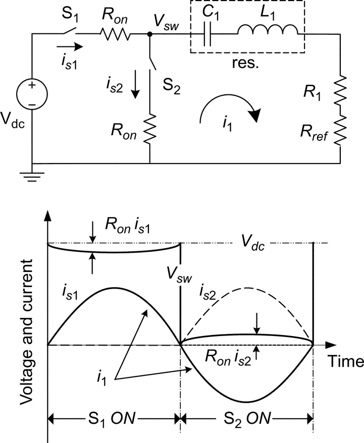
The class-D output voltage is square wave and fixed, independent of the load or coupling variations. Only the fundamental harmonic of current (at receiver coil resonance ω0) contributes to the wireless power transfer, and the other harmonics (although small as are blocked by the resonance) cause dissipation in the transmitter coil. For moderately large transmitter coil loaded quality factor (![]() ), the coil current would be close to sinusoidal, operating at its series resonance frequency that is also ω0.
), the coil current would be close to sinusoidal, operating at its series resonance frequency that is also ω0.
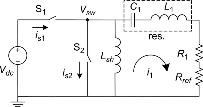
One of the challenges of class-D inverter in the megahertz frequency range is the switch output capacitive losses during S2 turn-on. A solution is to have the inverter output current lag the output voltage so it can self-commute to zero value during S2 turn-on (ZVS). To do so, one method is to have the impedance seen by the inverter to be slightly inductive by operating above the transmitter coil resonance frequency (![]() ) (Fig. 22.11). Note that the receiver coil is resonant at the operating frequency. Another way to provide lagging output current while not shifting the frequency from the transmitter coil resonance frequency is to add an inductive element Lsh in parallel to the inverter output [24] (Fig. 22.12). The Lsh provides the negative current required for the Vsw to self-commute to zero during S2 turn-on (ZVS).
) (Fig. 22.11). Note that the receiver coil is resonant at the operating frequency. Another way to provide lagging output current while not shifting the frequency from the transmitter coil resonance frequency is to add an inductive element Lsh in parallel to the inverter output [24] (Fig. 22.12). The Lsh provides the negative current required for the Vsw to self-commute to zero during S2 turn-on (ZVS).

22.6.2 Class-E Inverter
The series-resonant transmitter coil (as for class-D) requires high amount of current that increases FET gate driver losses. The parallel-resonant coil, in the other hand, reduces the current rating of the switches by circulating it through the resonant tank. However, it produces high voltages across the switches that increase the FET output capacitive losses. A combination of series- and parallel-resonant transmitter coil would take advantage of low voltage rating of series-resonant and low current rating of parallel-resonant coil. Class-E inverter satisfies these conditions with doubled-tuned output circuit [25]. Fig. 22.13 shows the class-E inverter with ideal waveforms. The inverter operates between the transmitter series resonance frequency and the one of transmitter in parallel with the Csh.

An advantage of class-E compared with class-D with ZVS is that the output voltage slope approaches zero during the S turn-on and makes class-E generally more efficient than class-D. For the switch voltage and its slope to be zero at switch turn-on, it is a function of Lchoke, Csh, ![]() , and the oscillations in the Csh-C1-L1 tank during switch turn-off. This makes the class-E inverter more complicated to design and prone to nonoptimum operation when coupling factor and load vary, which are common characteristics of WPT systems [22].
, and the oscillations in the Csh-C1-L1 tank during switch turn-off. This makes the class-E inverter more complicated to design and prone to nonoptimum operation when coupling factor and load vary, which are common characteristics of WPT systems [22].
22.7 Efficient Magnetic Link Design
Earlier in the chapter, it was shown that the maximum link efficiency ![]() is a function of k2Q1Q2 in which k is the coupling factor between the transmitter and receiver coils with quality factors of Q1 and Q2, respectively. To enhance the link efficiency, not only the coupling factor needs to increase, but also the coil quality factors should improve. This section's focus would be on the methods to increase the coupling and quality factors.
is a function of k2Q1Q2 in which k is the coupling factor between the transmitter and receiver coils with quality factors of Q1 and Q2, respectively. To enhance the link efficiency, not only the coupling factor needs to increase, but also the coil quality factors should improve. This section's focus would be on the methods to increase the coupling and quality factors.
22.7.1 Effect of Link Dimension
The magnetic design of inductive WPT system includes the design of link dimensions, coil shape, placement, and the type of material and conductor used in them. The coupling factor between the transmitter and receiver coils, with self-inductances of L1 and L2, is ![]() in which M is the mutual inductance between the two coils. In simple approximation for concentric-turn coils, the coupling factor is related to the ratio of the two-coil surface areas and inversely to the distance between them. The closer the transmitter and receiver coils to each other, the larger the coupling between them. And for coils that are very close to each other, the maximum coupling happens with coils having the same sizes. As the distance between the coils increases, there is an optimum ratio between the coil surface areas that leads to maximum coupling factor. Fig. 22.14 shows an example of the effects of distance between coils and their relative sizes on the link maximum coupling factor.
in which M is the mutual inductance between the two coils. In simple approximation for concentric-turn coils, the coupling factor is related to the ratio of the two-coil surface areas and inversely to the distance between them. The closer the transmitter and receiver coils to each other, the larger the coupling between them. And for coils that are very close to each other, the maximum coupling happens with coils having the same sizes. As the distance between the coils increases, there is an optimum ratio between the coil surface areas that leads to maximum coupling factor. Fig. 22.14 shows an example of the effects of distance between coils and their relative sizes on the link maximum coupling factor.

22.7.2 Effect of Coil Shape and Alignment
Circular coil is the most common form for the WPT resonator due to its symmetry, simplified analysis, and ease of fabrication. Other common coil forms include square and rectangular types.
Another important criterion that affects the coil shape is the misalignment between the transmitter and receiver coils. Misalignment tolerant inductive WPT systems are designed such that a specified misalignment between the coils does not drop the efficiency and power transfer significantly [12]. Such systems provide spatial freedom of movement to the receiver coil that is beneficial for most WPT applications. For example, Fig. 22.15A shows the coupling factor k changes versus misalignment between the transmitter and receiver coils for two transmitter sizes. The more misalignment tolerant system has a larger transmitter coil to allow for small movements in the receiver coil while having minimal changes in k. Fig. 22.15B shows that for a fixed misalignment distance, the coupling factor drop is lower for large transmitter coil compared with the small coil. Another method to improve the misalignment tolerance is to have multiple transmitter coils [26]. There are other factors, beside the misalignment tolerance, that affect the size and shape of coil, such as self-inductance and geometric constraints. The receiver side coil has typically more geometric constraints—for example, in a biomedical implant inside the body—and the WPT design process starts with the receiver coil followed by the transmitter.

22.7.3 Effect of Ferrite Core
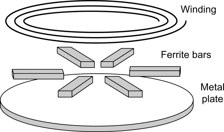
Another way to increase the coupling factor is to use soft magnetic materials such as ferrite cores. The magnetic flux lines follow the path of minimum reluctance; therefore, the high permeable ferrite core can be used to shape the field and increase the coupling. As the ferrite cores are placed on one side of the transmitter/receiver coils to enhance the coupling, they also shield the magnetic field from being exposed to the surrounding objects. This helps the inductive WPT system satisfy the health and safety requirements associated with high magnetic field strengths. In some applications, adding a metal plate to the coil helps shielding the high frequency magnetic fields from penetrating into nearby objects and reducing the EMI disturbance (Fig. 22.16).
A ferrite material with high saturation flux density, low AC power loss, and high bulk resistivity and permeability is beneficial in WPT systems. The most common types of ferrites used in inductive WPT systems are MnZn and NiZn ferrites. The MnZn ferrite has high permeability and high saturation flux density, while the NiZn ferrite has lower permeability and high bulk resistivity. The high-permeability ferrite increases the magnetic energy storage per geometric constraints, such as coil self-inductance. A ferrite with high bulk resistivity reduces the high-frequency-induced eddy and displacement currents.
A ferrite core increases not only the coupling factor and inductance but also the power dissipation. For sinusoidal excitation, the core loss is a function of frequency and magnetic flux density in the core. Its effects on the coil are well described by the coil quality factor Q. Increasing the coil inductance and resistance is somehow compensated in the quality factor that directly influences the link efficiency. However, other system requirements such as high inductance, magnetic field shielding, and high coupling factor are achieved by using ferrite cores in the transmitter and receiver coils.
22.7.4 Effect of Coil Winding
Reducing the coil winding AC resistance is an important step in magnetic link design as it increases the coil quality factor and link efficiency. Depending on the operating frequency, the winding conductor can be solid, foil, tubular, or litz. Solid round conductor is the most basic type of conductor, and its properties (such as resistance and inductance) have been well studied and determined. Solid wire is a building block of many types of wires such litz, and understanding its behavior is a critical step in the winding design. The AC power loss inside a current-carrying conductor is due to the high frequency eddy currents induced in it by the time-varying (1) internal magnetic field (skin effect) and (2) external magnetic field (proximity effect). The skin and proximity effects are orthogonal in round conductors and can be investigated separately. In the skin effect, the current flows mostly in the skin-depth region of the conductor, leaving the inner part having almost zero current flow (tubular conductor) that increases the AC resistance. One solution is to have multiple insulated concentric tubular conductors with optimum current flow to reduce the AC resistance [27]. With the conductor radius close to skin depth, the current flow is close to uniform. At high frequencies—mostly above a megahertz—the solid conductor can be superior to other conductor types due to its low AC power loss, low cost, and ease of manufacturing.
A potential type of conductor is foil wire that can be used in inductive WPT systems [28]. Copper foils with thicknesses close to skin depth in the multimegahertz frequency range (Cu skin depth is between 65 and 15 μm in the 1–20 MHz) are commercially available and affordable. In addition, with the state-of-the-art printed wiring (flexible) boards and electroplating methods, efficient inductors can be designed and fabricated. The other advantages of using foil conductor include high-current-carrying capability due to large cross-sectional area and improved thermal performance, and the inductors with low overall thickness can be designed. The foil conductor characteristics such AC resistance and inductance have been extensively studied in the literature for various applications. The most common application is in transformer windings with magnetic core surrounding the conductor [29]. This forces the magnetic field contours to be parallel with the foil and simplifies the determination of foil impedance in to a 1D analysis. In inductive WPT, however, the magnetic core—if present—is located on one side of the coil, and the field contours have 2D pattern requiring numerical methods such as finite element (FE) analysis to determine the inductor impedance.
Another way to reduce the AC resistance of a conductor—with thickness (or radius) much bigger than the skin depth—is to have the current flow uniform across the conductor cross section. To do so, the conductor needs to be divided into multiple insulated skin-depth-sized strands, with each strand seeing the same amount of magnetic flux. This can be done by twisting the strands such that each one of them occupies all the positions across the conductor in a full twist. This structure is litz wire, and its principles can be applied on different types of conductors to reduce the AC resistance [30]. The most common type of litz wire is made of solid round strands. However, same principles can be applied to design other forms of litz wire with rectangular foil strands [31]. Litz wire is a common choice of inductor wire at frequencies up to few megahertz, above which the need for very thin strands (close to skin depth) makes the manufacturing of litz wire expensive.
In the inductors with multiple turns, the power losses are divided into skin and proximity dissipations. The skin effect loss can be reduced by optimum design of a single-turn winding. The proximity effect, in the other hand, depends on the field of nearby turns. The complete structures of coil, including the number of turns, layers, distance between them, and existence of ferrite core, are the design parameters for minimizing proximity effect and AC resistance. For efficient coil design in WPT system, the coil quality factor Q is the main parameter of interest. Therefore, not only the winding AC resistance needs to be reduced, but also the coil inductance would have to increase. As a coil structure with minimum AC resistance does not necessarily have the maximum inductance, the coil quality factor would be the main optimization objective. In a broader link design objective, both the transmitter and receiver need to be considered by maximizing k2Q1Q2.
22.8 Summary
This chapter covered different methods of WPT with the main focus on weakly coupled inductive WPT systems. Such systems are increasingly getting popular due to the advantages they bring compared with wired power transfer. Not only inductive WPT systems offer extended freedom of movement for source and load (relatively) such as in EVs, but also they are beneficial in applications where there is limited access to the load such as in biomedical implants. A typical two-coil inductive WPT was analyzed, and the system parameters including the magnetic link efficiency were derived. In order to increase the maximum link efficiency, both the coupling factor and coil quality factors need to increase. The effects of coil size, shape, structure, and placement were discussed to maximize link efficiency. In weakly coupled inductive WPT systems, the impedance reflected to the transmitter coil as seen by the inverter is quite small, and the inverter needs to be designed depending on the magnetic link. For high frequency (megahertz range) inverters, class-D (ZCS and ZVS) and class-E inverters were analyzed, and their (dis) advantages were discussed.