
Drive Types and Specifications
Yahya Shakweh AEC, London, United Kingdom
Abstract
In every industry, there are industrial processes of some form, which require adjustments for either normal operation or optimum performance. Such adjustments are usually accomplished with a variable speed drive system. They are an important part of automation. They help to optimize the process, reduce investment costs, energy consumption, and energy cost.
Keywords
Variable speed drive; Electric motor; Transformer; Converters; Inverters; Rectifier
29.1 An Overview
29.1.1 Introduction
In every industry, there are industrial processes of some form, which require adjustments for either normal operation or optimum performance. Such adjustments are usually accomplished with a variable speed drive (VSD) system. They are an important part of automation. They help to optimize the process, reduce investment costs, energy consumption, and energy cost.
There are three basic types of VSD systems: electric drives, hydraulic drives, and finally mechanical drives. This chapter focuses mainly on electric drives.
A typical electric VSD system consists of three basic components: the electric motor, the power converter, and the control system, as illustrated in Fig. 29.1. The electric motor is connected directly or indirectly (through gears) to the load. The power converter controls the power flow from an AC supply (often via a supply transformer) to the motor by appropriate control of power semiconductor switches (part of the power converter).

With recent advances of power semiconductor and converter topologies, electric VSDs are witnessing a revolution in applications including computer peripheral drives, machine tools and robotic drives, test benches, fan pumps and compressors, paper mill drives, automation, traction and ship propulsion, and cement mill and rolling mill drives.
For a proper control system, the VSD system variables, both mechanical and electric, are required for control and protection. Signals are usually derived from sensors, whose outputs are very much dependent on the control strategy employed and the functionality required.
This chapter introduces electric VSDs and briefly describes their benefits. It examines their classifications from different perspectives. Their specification requirement to meet applications of different industries is briefly outlined. Various VSD topologies have been carefully examined and compared with each other. A selection of modern VSD applications are examined and briefly commented upon.
29.1.2 Historical Review
In order to appreciate electric VSDs, significant dates in the evolution of electric drives are summarized in Table 29.1 [1].
Table 29.1
Historical review
| Year | Key advancement |
| 1886 | The birth of the electric variable speed drive system represented by Ward-Leonard system |
| 1889 | The invention of squirrel cage induction motor |
| 1890 | The slip-ring induction motor drive—speed control via rotor resistance control |
| 1904 | Kramer drives—introduce a DC link between the slip rings and the AC supply |
| 1911 | Variable speed system based on induction motor with a commutator on the rotor |
| 1923 | Ignitron made controlled rectification possible |
| 1928 | The invention of thyratron and grid-controlled mercury-arc rectifiers |
| 1930 | DC-to-AC power inversion |
| 1931 | AC-to-AC power conversion by cycloconverters |
| 1950 | Silicon-based power switches |
| 1960 | Thyristors (SCRs) became available, and variable speed drives began |
| 1961 | Back-to-back reversing DC drive introduced |
| 1960s | Power semiconductor voltage and current ratings grew and performance characteristics improved |
| 1970 | The concept of packaging industrial drives was introduced |
| 1972 | First integrated motors with DC converter |
| 1973 | Isolated thyristors packages |
| 1970s | The principle of vector control (field-oriented control) evolved |
| 1983 | Plastic molding made their first significant impact on VSDs |
| 1985 | Direct torque control as a concept |
| 1990 | Integrated power modules |
| 1992 | A new packaging trend emerged |
| 1996 | Universal drives (a general purpose open-loop vector drive, a closed-loop flux vector drive, and a servo drive) |
| 1998 | Complete AC/AC integral converter up to 15 kW |
| 1998 | Medium-voltage pulse-width-modulated voltage-source inverter drives—became a commercial product |
The increased popularity of electric VSD systems, witnessed in recent years, may be explained by the many advantages a VSD can offer. Such advantages include operation at speeds significantly different from the synchronous speed, energy saving, reduced mechanical shock, improved process performance, improved efficiency, reduced mechanical wear, increased plant life, reduced total ownership costs, reduced system fault levels, and reduced AC disturbances in certain applications. Furthermore, modern electric drives are equipped with many features, including serial communication, remote control, diagnostics, and trip history. In the low-voltage low-power arena, packaged electric drives are becoming a commodity product. The disadvantages of such a system are also recognized. They include the need for extra space to accommodate the equipment, cooling, capital cost, noise, and power system harmonic effects. The following is a brief review of some of the benefits and drawbacks of VSDs.
29.1.3 Advantages of VSD
The author suggests that VSDs benefit most industrial processes with some form of drive. The challenge has often been how to quantify these benefits. The energy saving potential of VSD can be easily quantified, particularly for fan and pump drive applications.
29.1.3.1 Energy Saving
Electric VSD provides savings in two ways: (a) directly by consuming less energy and (b) indirectly by improving the product quality. The latter is often more difficult to quantify.
Direct energy saving is possible only with centrifugal loads such as centrifugal pumps and fans. Such loads are often run at fixed speeds. Traditionally, an automatic valve, or some other mechanical means, is used to vary fluid flow rates in pumps. However, if a VSD is used, then the motor speeds can be controlled electronically to obtain a desired flow rate and can result in significant energy savings.
On the basis of the laws of affinity for centrifugal loads,
• the volume of flow is directly proportional to speed,
• pressure is proportional to the square of the speed,
• input power is proportional to the cube of the speed.
The affinity law states that the power consumption is proportional to the cube of the motor speed. This implies that if the speed is halved, then the power consumption is reduced to one-eighth. So, energy savings occur as the requirement for volume decreases. If, for example, a cooling system calls for operation at 50% airflow volume, it requires only 12.5% of the power needed to run the system at 100% volume. Because power requirements decrease faster than the reduction in volume, there is a potential for significant energy reduction at lower volume.
Generally, centrifugal pumps and fans are sized to handle peak volume requirements that typically occur for short periods. As a result, centrifugal pumps and fans mostly operate at reduced volumes.
Opening or closing of a damper allows the airflow of fans to be controlled. Restricting the airflow causes the motor to work hard even with a low throughput.
With a VSD, the speed of the fan can be reduced, thus giving the opportunity to reduce energy consumption. Adjusting the speed of the motor regulates the airflow. The control can be achieved by monitoring humidity, temperature, flow, etc. The lower the required throughput, the greater the energy saved.
It has been estimated that the payback period of a 50 kW fan or pump VSD equipment operating 2000 h/year is 1.9 years for operation at 75% speed and 1.23 years for 50% speed. It has been assumed that the cost of the VSD is £5.5 k and the cost of power is £0.05/kW.
29.1.3.2 Improved Process Control
Using VSDs to improve process control results in more efficient operating systems. The throughput rates of most industrial processes are functions of many variables. For example, throughput in continuous metal annealing depends on, among other factors, the material characteristics, the cross-sectional area of the material being processed, and the temperature of one or more heat zones. If constant speed motors are used to run conveyors on the line, it must either run without material during the time required to change the temperature in a heat zone or produce scrap during this period. Both choices waste energy or material.
With VSDs, however, the time needed to change speed is significantly less than the time it takes to change heat-zone temperature. By adjusting the material flow continuously to match the heat-zone conditions, a production line can operate continuously. The results are less energy use and less scrap metal.
29.1.3.3 Reduced Mechanical Stress (Soft Starts)
Starting a motor on line power increases stress on the mechanical system, for example, belts and chains. Direct on-line start-up of an induction motor is always associated with high inrush current with poor power factor.
VSD can improve the operating conditions for a system by giving a smooth, controlled start and by saving some energy during starting and running. Smoother start-up operation will prolong life and reduce maintenance, but it is difficult to do more than make an estimate of the cost advantages of these. The benefits of soft start, inherent in VSD, are that it eliminates the uncontrolled inrush of current that occurs when stationary motor is connected to full line voltage, and also the inevitable suddenly applied high start-up torque. Benefits are that the power wasted by current inrush is eliminated and that the life of the motor and the driven machine are prolonged by the gentle, progressive application of torque.
29.1.3.4 Improved Electrical System Power Factors
When a diode supply bridge is used for rectification, electric VSDs operate at near-unity power factor over the whole speed range (the supply delivers mostly real power). When a fully controlled thyristor supply bridge is used (as in DC, cyclo, and current source drives), the power factor starts at around 0.9 at full speed and proportionately worsens as speed declines due to front-end thyristors (typically 0.45 at 50% speed and 0.2 at 25% speed).
Modern pulse-width modulated (PWM) drives convert the three phases AC line voltage to a fixed-level DC voltage. They do this regardless of inverter output speed and power. The PWM inverters, therefore, provide a constant power factor regardless of the power factor of the load machine and the controller installation configuration, for example, by adding a reactor or output filter between the VSD and the motor.
29.1.4 Disadvantages of VSD
The cost of VSD is generally space, cooling, and capital cost. Some of the drawbacks are the following:
• Motor derating
• Supply harmonics
The PWM voltage-source inverter (VSI) drives, equipped with fast-switching devices, add other possible problems such as (a) premature motor insulation failures, (b) bearing/earth current, and (c) electromagnetic compatibility (EMC).
29.1.4.1 Acoustic Noise
In some installations, placing a VSD on a motor increases the motor's acoustic noise level. The noise occurs when the drive's nonsinusoidal (current and voltage) waveforms produce vibration in the motor's laminations. The nonsinusoidal current and voltage waveforms produced by the VSD are the result of the transistor switching frequency and modulation in the DC-to-AC inverter. The switching frequency, fixed or variable, determines the audible motor noise. In general, the higher the carrier frequency, the closer the output waveform is to a pure sine wave. One method of reducing audible motor noise is full-spectrum switching (random switching frequency). The VSD manufacturers accomplish full-spectrum switching by an algorithm within the VSD controller. The motor performance is optimized by evaluating motor characteristics, including motor current, voltage, and the desired output frequency. The resulting frequency band, though audible to humans, produces a family of tones across a wide frequency band. So, the perceived motor noise is considerably less than it would be with a single switching frequency.
Motor noise may not present a problem. Relevant factors include motor locations and the amount of noise produced by other equipment. Traditionally, motor noise level is reduced by adding an LC filter between the VSD and the motor, that is, reducing the high-frequency component of the motor voltage waveform. Modern PWM inverter drives run at very high switching frequency and with random switching frequency thus reducing the noise level too. Various methods have been proposed to reduce the magnetically generated noise, which is radiated from inverter-fed induction motors.
29.1.4.2 Motor Heating
Most motor manufacturers design their products according to NEMA standards to operate on utility-supplied power. Designers base their motors' heating characteristics and cooling methods on power supplied at fixed voltage and frequency.
For many drive applications, particularly those requiring relatively low power, inverters with a high switching speed can produce variable voltage and variable frequency with little significant harmonic content. With these, either standard or high-efficiency induction motors can be used with little or no motor derating. However, the inverters used in larger drives have limits on switching rate that cause their output voltages to contain substantial harmonics of orders 5, 7, 11, 13, and so on. These, in turn, cause harmonic currents and additional heating (copper and iron losses) in the stator and rotor windings. These harmonic currents are limited mainly by the leakage inductance. For simple six-step inverters, the additional power losses, particularly those in the rotor, may require derating of the motor by 10%–15%.
Existing constant speed drives often have an oversized induction motor. These can usually be converted to variable speed operation using the original induction motor. Most of the subsequent operation will be at lower load and lower loss than that for which the motor was designed.
Modern PWM-VSI drives produce a voltage wave with negligible lower-order harmonics. The wave consists of pulses formed by switching at relatively high frequency between the positive and negative sides of the DC link voltage supply. With larger motors that operate from AC supplies up to 6600 V, the rapid rate of change of the voltage applied to the winding may cause deterioration and failure in the insulation on the entry turns of standard motors.
On self-ventilated (fan-cooled) motors, reducing the motor shaft speed decreases the available cooling airflow. Operating a motor at full torque and reduced speed results in inadequate airflow. This consequently results in increased motor insulation temperature. This potentially can be damaging and can reduce the life of the motor's insulation or cause the motor to fail. One potential solution is to add a constant speed, separately driven cooling fan to the motor. This approach ensures adequate stator cooling over the whole speed range. However, the rotor will run hotter than designed as internal airflow remains a function of speed. As there are no windings in the rotor, insulation failure is not an issue, but bearings may run hotter and require more frequent lubrication.
Fan-cooled motors with centrifugal loads present less of a problem. Pumps and fans, for example, do not require full torque at reduced speeds. So, in these cases, there is less thermal stress on motors at reduced speeds. Centrifugal load does not cause the motor to exceed thermal limits defined by the insulation system.
29.1.4.3 Supply Harmonics
Current and voltage harmonics in the AC supply are created by VSD (as a nonlinear load) connected on the power distribution system. Such harmonics pollute the electric plant, which could cause problems if harmonic level increases beyond a certain level. The effect of harmonics can be overheating of transformers, cables, motors, generators, and capacitors connected to the same power supply with the devices generating the harmonics.
The IEEE 519 recommends practices and requirements for harmonic control in electric power systems. The philosophy of such regulations is to limit the harmonics injection from customers so that they will not cause unacceptable voltage distortion levels for normal system characteristics and to limit the overall total harmonic distortion of the system voltage supplied by the utility.
In order to reduce supply harmonics that are generated by VSDs equipped with a 6-pulse diode bridge rectifier, VSD equipment manufacturers adopt various techniques. Table 29.2 summarizes the most common methods and their advantages and disadvantages [2].
Table 29.2
Techniques used to reduce supply harmonics
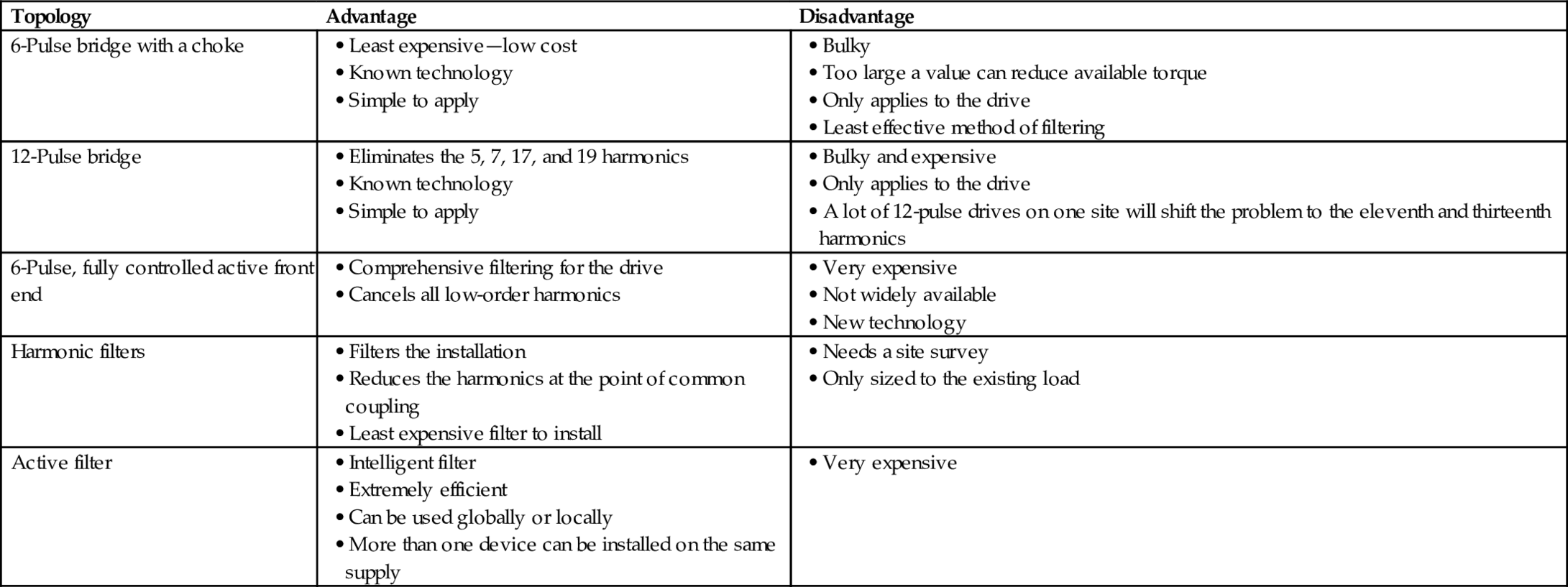
Ref. [2] quantifies the cost of these options as a percentage of the cost of a basic system with 6-pulse diode bridge. For low-power VSDs, the cost of a drive with a line reactor is estimated to be 120% of that without. A VSD with a 12-pulse diode bridge with a polygon transformer is 200% while for a double-wound transformer is 210%. The most expensive solution is that with active front end, estimated at 250%.
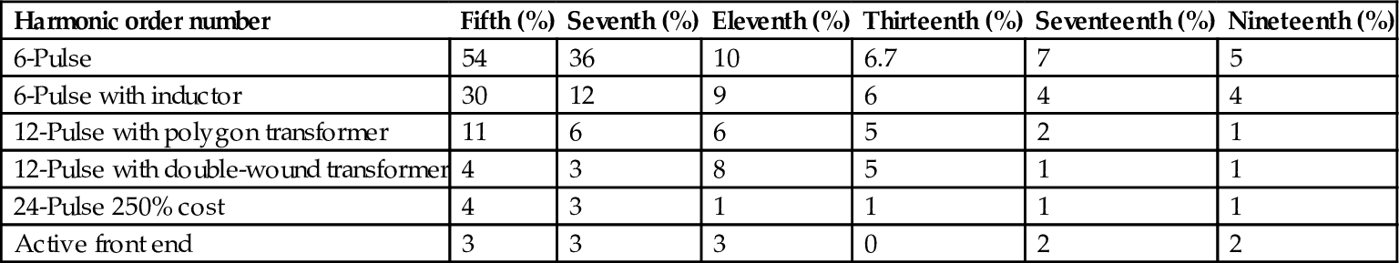
For 6-pulse converter, ![]() (5, 7, 11, 13, 17, 19, etc) order harmonics are generated. To minimize the effects on the supply network, recommendations are laid down by IEEE 519 as to the acceptable harmonic limits. For higher drive powers, therefore, either harmonic filtering or use of a higher converter pulse number is necessary. It is generally true that the use of a higher pulse number is the cheaper alternative. Ref. [2] also quantifies the harmonic levels generated by each of the above method; refer to Table 29.3 for a direct comparison.
(5, 7, 11, 13, 17, 19, etc) order harmonics are generated. To minimize the effects on the supply network, recommendations are laid down by IEEE 519 as to the acceptable harmonic limits. For higher drive powers, therefore, either harmonic filtering or use of a higher converter pulse number is necessary. It is generally true that the use of a higher pulse number is the cheaper alternative. Ref. [2] also quantifies the harmonic levels generated by each of the above method; refer to Table 29.3 for a direct comparison.
Table 29.3
Supply harmonics for different supply bridge configurations
| Harmonic order number | Fifth (%) | Seventh (%) | Eleventh (%) | Thirteenth (%) | Seventeenth (%) | Nineteenth (%) |
| 6-Pulse | 54 | 36 | 10 | 6.7 | 7 | 5 |
| 6-Pulse with inductor | 30 | 12 | 9 | 6 | 4 | 4 |
| 12-Pulse with polygon transformer | 11 | 6 | 6 | 5 | 2 | 1 |
| 12-Pulse with double-wound transformer | 4 | 3 | 8 | 5 | 1 | 1 |
| 24-Pulse 250% cost | 4 | 3 | 1 | 1 | 1 | 1 |
| Active front end | 3 | 3 | 3 | 0 | 2 | 2 |
29.2 Drives Requirements and Specifications
29.2.1 General Market Requirements
Some of the most common requirements of VSDs are high reliability, low initial and running costs, high efficiency across speed range, compactness, satisfactory steady-state and dynamic performance, compliance with applicable national and international standards (e.g., EMC, shock, and vibration), durability, high availability, ease of maintenance, and repairs.
The order and priority of such requirements may vary from one application to another and from one industry to another. For example, for low-performance drives such as fans and pumps, the initial cost and efficiencies are paramount, as the main reason for employing VSDs is energy saving. However, in other industries such as marine, the compactness of the equipment (high volumetric power densities) is a priority requirement due to shortage in space. In such environments, direct raw water cooling is the preferred choice as water is plentiful, and forced water cooling results in a more compact drive solution.
In critical VSD applications, such as military marine propulsion, reliability, availability, and physical size are very critical requirements. Cost is relatively less critical. However, achieving these requirements adds to the cost of the basic drive unit. Series and parallel redundancy of components enable the VSD equipment to continue operation even with failed components. These are usually repaired during regular maintenance. In other critical applications (such as hot mill strips or subsea drives), the cost of drive failures could be many times more expensive than the drive itself. For example, accessing a drive down on the seabed, many kilometers below the seawater level, could be very difficult.
This section identifies the VSD requirements in various drive applications in different industries.
29.2.1.1 The Mining Industry
The majority of early-generation large mine winders are DC drives. Modern plants and retrofits generally employ cycloconverters with AC motors. However, small mine winders (below 1 MW) tend to remain DC.
The main requirements are the following:
• High reliability and availability
• Fully regenerative
• Small number requiring single-quadrant operation
• High range of speeds
• High starting torque required
• High torque required continuously during slow-speed running
• Low-torque ripple required
• Low supply harmonics
• Low audible noise emissions
• Flameproof packaging
29.2.1.2 The Marine Industry
The requirements of this industry are the following:
• Reliability
• Ease of maintenance, that is, minimum component count and simple design
• Size and weight of equipment
• Transformerless, water-cooled VSD equipment is always preferred
Other desirable features include the following:
• A requirement for the integration of power management functions
• High volumetric power density (the smallest possible)
• Remote diagnostics, to allow faultfinding by experts onshore in critical situations
Drive powers are commonly in the range of 0.75–5.8 MW for thrusters and 6–24 MW for propulsion. The evolution in the commercial market is toward powers from 1 to 10 MW for propulsion. Higher powers are required for naval applications. The package drive efficiency must be equal to or better than 96%. Noise and harmonics problems are to be considered when using PWM inverters. The supply side harmonics produced must be capable of being filtered. Above 1 MW, power converters are usually equipped with a 12-pulse supply bridge, given today's technology.
Two-quadrant operation is required in general; hence, a diode supply bridge is adequate. Occasional requirement for crash stops forces the use of dynamic brake chopper. DC bus can be advantageous for supply to wharf loading equipment, but the drive power ranges are such that commercially available products already adequately serve this application.
The use of standard AC machines is desirable; however, if motors matched to the inverter prove to be cheaper, their use could be preferred. Low-noise emission (acoustic and electromagnetic) is very important. There is no requirement for high torque at low speed. Programming and expanded input and output capabilities are required to avoid the need for additional programmable logic control (PLC).
29.2.1.3 The Process Industries
The main requirements of this market are the following:
• Initial purchase price (long-term cost of ownership does not generally influence purchasing decision)
• Efficiency in continuous processes
• Reliability
• Ease of maintenance
• Bypass facility
The industry preference is for air-cooled drives. It is perceived that air-cooled drives are less costly than their water-cooled equivalents. Customers often have the belief that water and electricity does not mix well and are wary of problems with leaks. The exception is the offshore industry where equipment size is paramount, and therefore, water cooling is standard. In general, there is no perceived requirement for space saving in majority of process plants. The desirable features often requested by customers are ease of maintenance and good diagnostic facilities.
The market requirement is for cost-effective, stand-alone drives at various power levels from a fraction of a kW up to 30 MW. The use of standard AC machines is desirable. However, if nonstandard but simpler and cheaper machines can be offered, an advantage could be gained:
• Two-quadrant operation for fans, pumps, and compressors.
• Four-quadrant operation for some test benches.
• Control must allow additional functions such as temperature protection, motor bearing temperature, and flow and pressure control.
• There is no requirement, in general, for field weakening.
• The harmonics produced by the drive, imposed on the power system, should not require a harmonic filter. Harmonics must be minimized.
In the low-voltage (LV) arena, the PWM-VSI is dominating the market. In the medium-voltage (MV) arena, there are a number of viable drive solutions—load-commutated inverters (LCIs) and cycloconverters. However, there is a developing market for MV PWM-VSI drives.
29.2.1.4 The Metal Industries
The requirements of this industry are the following:
• Reliability—high availability.
• Efficiency of the equipment—long-term costs of ownership.
• Low maintenance costs—this has been a key factor in the move from DC to AC.
• Power supply system distortion—more onerous regulations from the supply authorities.
• Initial purchase cost—very competitive market and large drive costs have a big impact on total project costs.
• Confidence in the supplier and their solution.
The following is a list of desirable features:
• Programmable system drives with powerful programming tools.
• Preference for air-cooled stacks but water-cooled is acceptable if a water-to-air heat exchanger is used.
• Powerful maintenance and diagnostic tools.
• Low EMC noise signature.
• Ability to interface to existing automation system via network, fieldbus, or serial link.
• Physical size of equipment is often not an important consideration.
• Fire protection systems integral to drive equipment.
The main market concerns are (a) EMC regulations, (b) effects on motor insulation of higher voltage levels, and (c) cooling with “dirty” mill water is not acceptable. The maintenance of deionized water circuits is a big issue.
29.2.2 Drive Specifications
Failure to properly specify an electric VSD can result in a conflict between the equipment's supplier and the end user. Often, the cost can be delayed project completion and/or the loss of revenue.
In order to avoid such a problem, requirement specifications should reflect the operating and environmental conditions (Table 29.4). The equipment supplier and the customer need to work as partners and cooperate from the beginning of the project until successful commissioning and hand over. It is advisable that the end user procures the complete drive system, including system engineering, commissioning, and engineering support, from one competent supplier.
Table 29.4
Typical example of VSD specifications
| Variable | Specification |
| Application | Dynamometer application for a test bench |
| Motor type | Induction motor |
| Duty cycle | Continuous at full rating. 150% overload for 1 min every 60 min |
| Power rating | 100 kW |
| Supply voltage | 690 V±5% |
| Supply frequency | 50±0.05 Hz |
| Speed range | 1000:1 |
| Accuracy | 0.1% |
| Min/max speed | 0/1500 rpm |
| Torque dynamic response | <10 ms from 100% positive torque to 100% negative torque |
| Power factor | >96% lagging at all speeds |
| Efficiency | >98% at full load |
| Performance | Fully regenerative |
| Full torque at zero speed | |
| Ambient temperature | 0–40°C |
| Supply harmonics | G5/3, IEEE519 |
| Life expectancy | >5 years |
| MTBF | >50,000 h |
| MTTR | <2 h |
| IP rating | IP45 |
| IEEE 519 | IEEE recommended practices and requirements for harmonic control in electric power systems |
| IEC 60146 | Semiconductor converters. Specifications of basic requirements |
| IEC 61800 | Adjustable speed electric power drives systems |
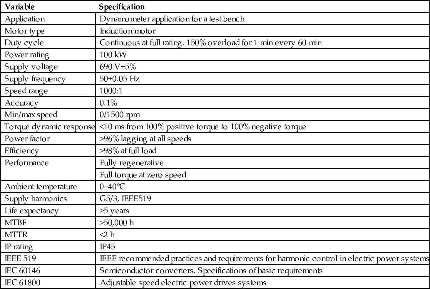
It is one of the first priorities to identify applicable national and international standards on issues related to EMC, harmonics, safety, noise, and smoke emissions during faults, dust, and vibration. Overspecifying the requirements could often result in a more expensive solution than necessary. Underspecifying the requirements result in poor performance and disappointment.
As far as the end user is concerned, they need to specify the drive interfaces—the AC input voltage, shaft mechanical power, and shaft speed. The torque and current are calculated from these. Frequency and power factor depend on the choice of motor.
For a high-power drive, it is always recommended to carry out a “harmonic survey.” Such a survey will reveal the existing level of harmonics and quantify the impact of the new drive on the harmonic levels.
29.3 Drive Classifications and Characteristics
Table 29.5 illustrates the most commonly used classifications of electric VSDs. In this section, particular emphases will be given to classification by applications and by converter types.
Table 29.5
Classifications of electric VSD
| By application | By devices | By converter | By motors | By industry | By rating |
|
• Special motors: SRM, BDCM, stepper, actuators, linear motor |
|||||
|
• Marine |
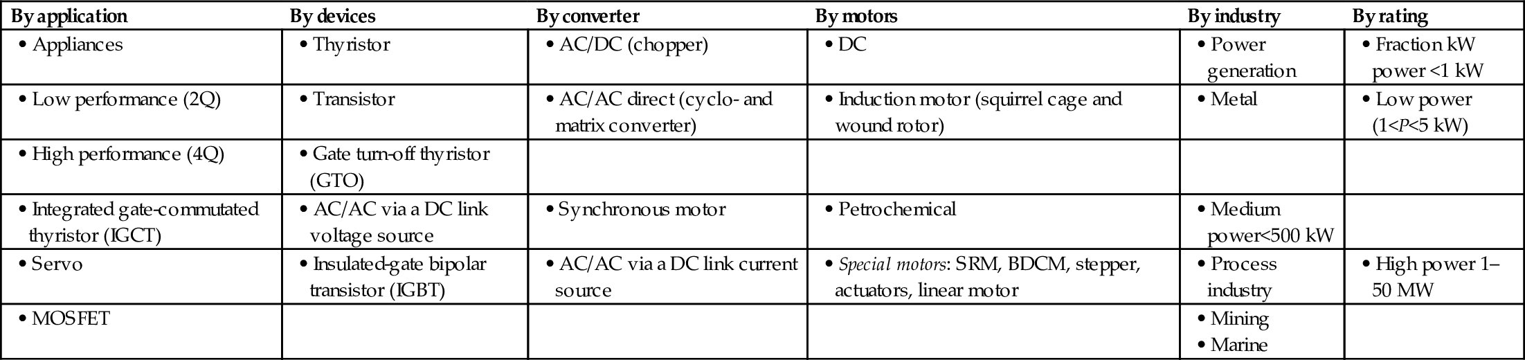
Other classifications, not listed in Table 29.5, include the following:
• Working voltage: low voltage <690 V or medium voltage (MV) 2.4–11 kV
• Current type: unipolar or bipolar drive
• Mechanical coupling: direct (via a gearbox) or indirect mechanical coupling
• Packaging: integral motors as opposed to separate motor inverter
• Movement: rotary movement, vertical, or linear
• Drive configuration: stand-alone system and DC link bus
• Speed: high speed and low speed
• Regeneration mode: regenerative or nonregenerative
• Cooling method: direct and indirect air and direct water (raw water and deionized water)
Section 29.2 deals with the subject of drives requirement and specification from applications point of view, while Section 29.5 deals with drive topologies from the point of view of motor classifications.
29.3.1 Classification by Applications
Under this classification, there are four main groups:
• General purpose drives
• System drives
• Servo drives
Table 29.6 describes the main features of these groups and lists typical applications.
Table 29.6
Classification of electric VSD by application
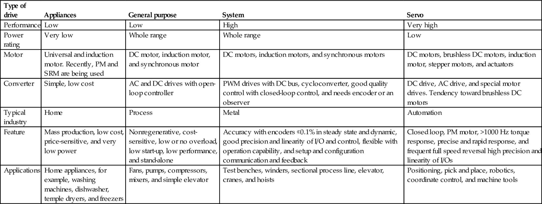
| Type of drive | Appliances | General purpose | System | Servo |
| Performance | Low | Low | High | Very high |
| Power rating | Very low | Whole range | Whole range | Low |
| Motor | Universal and induction motor. Recently, PM and SRM are being used | DC motor, induction motor, and synchronous motor | DC motors, induction motors, and synchronous motors | DC motors, brushless DC motors, induction motor, stepper motors, and actuators |
| Converter | Simple, low cost | AC and DC drives with open-loop controller | PWM drives with DC bus, cycloconverter, good quality control with closed-loop control, and needs encoder or an observer | DC drive, AC drive, and special motor drives. Tendency toward brushless DC motors |
| Typical industry | Home | Process | Metal | Automation |
| Feature | Mass production, low cost, price-sensitive, and very low power | Nonregenerative, cost-sensitive, low or no overload, low start-up, low performance, and stand-alone | Accuracy with encoders ⋘0.1% in steady state and dynamic, good precision and linearity of I/O and control, flexible with operation capability, and setup and configuration communication and feedback | Closed loop, PM motor, >1000 Hz torque response, precise and rapid response, and frequent full speed reversal high precision and linearity of I/Os |
| Applications | Home appliances, for example, washing machines, dishwasher, temple dryers, and freezers | Fans, pumps, compressors, mixers, and simple elevator | Test benches, winders, sectional process line, elevator, cranes, and hoists | Positioning, pick and place, robotics, coordinate control, and machine tools |
29.3.2 Classification by Type of Power Device
The silicon-controlled rectifier (SCR), also known as the thyristor, is the oldest controllable solid-state power device and still the most widely used power device for MV—AC voltages between 2.4 and 11 kV—high-power drive applications. Such devices are available at high voltages and currents, but the maximum switching frequency is limited and requires a complex commutation circuit for VSI drive. The SCRs are therefore most popular in applications where natural commutation is possible (e.g., cycloconverters and LCI current source converters).
The gate turn-off thyristor (GTO) has made PWM-VSI drives viable in LV drive applications. The traction industry was one of the first to benefit from such a device on a large scale. Complex gate drive and limited switching performance, combined with the need for a snubber circuit, limited this device to high-performance applications where the SCR-based drives could not give the required performance.
The main power devices available in the market can be divided into two groups as shown in Table 29.7.
Table 29.7
Power devices used in the VSD converters

Bipolar-/MOSFET-type transistors have witnessed significant popularity in the late 1980s; however, they have been replaced by the IGBT that combines the characteristics of both devices—the current handling capability of the bipolar transistor and the ease of drive of the MOSFET.
Traction inverters are designed for DC link voltages between 650 V DC and 3 kV DC with ratings up to 3 MW. The first generation of widely used traction inverter equipment was GTO-based, while the latest generation is almost exclusively IGBT-based. Conversion to IGBT has enabled a 30%–50% reduction in cost, weight, and volume of the equipment.
Early attempts to use GTOs in MV applications failed because of their high cost, snubber requirements, and associated snubber energy loss, which is proportional to the square of the supply voltage. Energy-recovery circuitry enables recovery of most of the snubber energy but adds to the cost and complexity of the converter. With high-voltage IGBT and IGCT, MV PWM-VSI has become commercially available with supply voltage up to 6.6 kV and power rating in excess of 19 MW.
29.3.3 Classification by the Type of Converter
The power converter is capable of changing both its output voltage magnitude and frequency. However, in many applications, these two functions are combined into a single converter by the use of the appropriate switching function, for example, PWM. By appropriate control of the stator frequency of AC machines, the speed of rotation of the magnetic field in the machine's air gap and thus output speed of the mechanical drive shaft can be adjusted. As the magnetic flux density in the machine must be kept constant under normal operation, the ratio of motor voltage over stator frequency must be kept constant.
The input power of the majority of VSD systems is obtained from sources with constant frequency (e.g., AC supply grid or AC generator). In order to achieve a variable-frequency output energy, an AC/AC converter is needed. Some converters achieve direct power conversion from AC/AC without an intermediate step (e.g., cycloconverters and matrix converters). Other converters require DC link (as current source or voltage source).
In all AC VSDs, the direction of shaft rotation is reversed by simply changing the phase rotation of the inverter through the sequence of driving the switches.
29.3.3.1 DC Static Converter
This drive employs the simplest static converter. It is easily configured to be a regenerative drive with a wide speed range. Table 29.8 summarizes its key features.
Table 29.8
Converter topologies


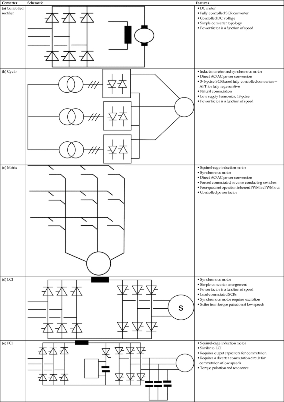
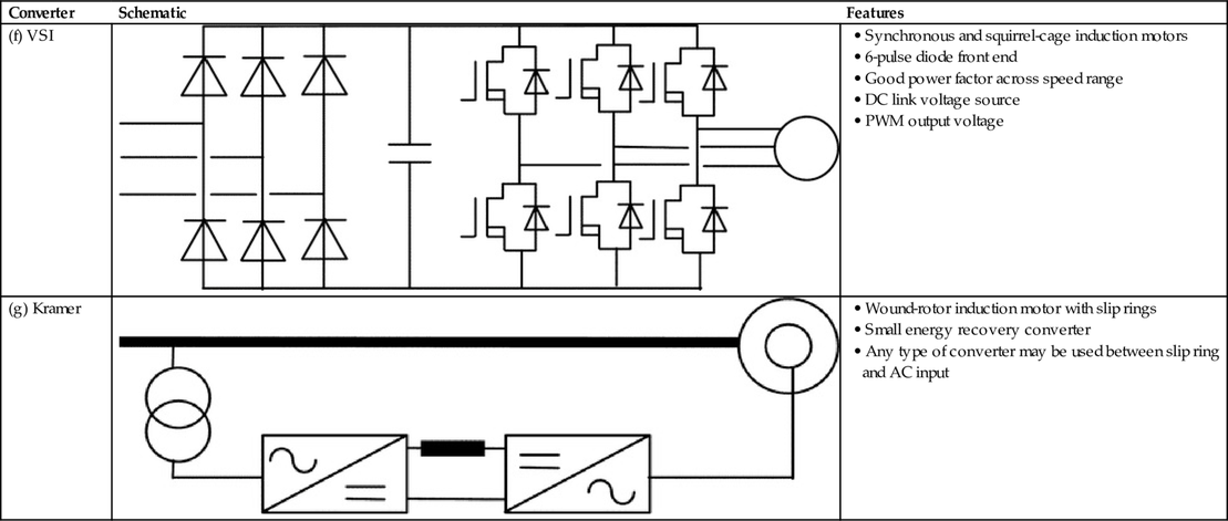
High torque is available throughout the speed range with excellent dynamic performance. Unfortunately, the motor requires regular maintenance, and the top speed often is a limiting factor. Commutator voltage is limited to around 1000 V, and this limits the maximum power available. The continuous stall torque rating is very limited due to the motor's commutator.
29.3.3.2 Direct AC/AC Converters
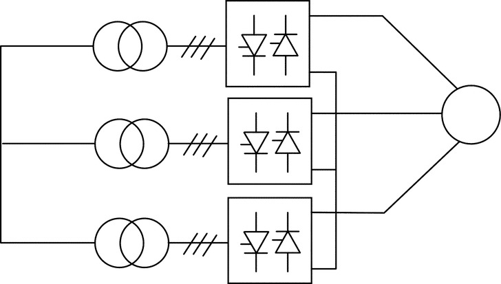
Cyclo-converter
A typical cycloconverter comprises the equivalent of three antiparallel 6-pulse bridges (for regenerative converter) whose output may be operated in all four quadrants with natural commutation. The main features of cycloconverters are listed in Table 29.8. This type of drive is best suited for high-performance high-power >2 MW drives where the maximum motor frequency is <33% of the mains frequency.
Matrix-converter
The force-commutated cycloconverter (better known as a matrix converter) represents possibly the most advanced state of the art at present, enabling a good input and output current waveform and eliminating the DC link components with very little limitation in input-to-output frequency ratio. This type of converter is still at its early stages of development. The main advantage of this drive is the ability to convert AC fixed-frequency supply input to AC output without DC bus. It is ideal for integrated motor drives with relatively low power ratings. Major drawbacks include (a) the increased level of silicon employed (bidirectional switches), (b) its output voltage is always less than its input voltage, and (c) complexity of commutation and protection.
Matrix converters provide direct AC/AC power conversion without an intermediate DC link and the associated reactive components. They have substantial benefits for integrated drives as outlined below:
• Reduced volume due to the absence of DC link components.
• Ability to operate at the higher thermal limit imposed by the power devices.
• Reduced harmonic input current compared with diode bridge.
• Ability to regenerate into the supply without dumping heat in dynamic braking resistors.
• Matrix converters have not been commercially exploited because of voltage ratio limitation, device count, and difficulties with current commutation control and circuit protection.
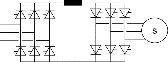
29.3.3.3 Current Source Inverter
The output of this inverter is rectangular blocks of current from the motor bridge supplied from a supply converter whose output is kept at constant current by a DC link reactor and current servo. This type of inverter is typically based on fast thyristors.
Load commutated inverter
Natural commutations of thyristors are usually achieved with synchronous machines at speeds >10%. Natural commutation is induced as a result of the presence of the motor's electromotive force (EMF); this is called load commutation hence the drives' other name of LCI. At low speeds, the motor voltage is too low to give motor bridge commutations. This is achieved by using the supply converter. Induction-motor LCI drives can be supplied by adding a large capacitor on the motor terminals.
The LCI drive covers a wider speed range (up to 10,000 rpm) with power rating up to 100 MW. It gives full load torque throughout the speed range with moderate dynamic performance. Its simple converter design combined with a maintenance-free motor design (both induction and synchronous) has increased the popularity of these drives. It is still a popular solution for high-power drives (e.g., conveyors, pumps, fans, compressors, and marine propulsion).
The LCI drive has limited performance at low speeds. It also suffers from torque pulsation at 6 and 12 times the motor's frequency and beat frequencies. Critical speeds can excite mechanical resonance. Its AC power factor varies with speed. Torque pulsations can be reduced in 12-pulse systems if required.
Forced commutated inverter
Externally commutated current source converters with an induction motor are also a viable solution. To compensate for the inductive component in the motor current, a bank of capacitors are usually used at the motor terminals. The capacitor current is proportional to the motor voltage and frequency. Load commutation at high speed where the compensation current is high enough. Forced commutation at lower speed where the capacitive current is too low for compensation. Forced commutation is achieved using various techniques. The one shown above is based on DC link diverter that consists of a GTO, loading equipment in parallel with the diverting/compensating capacitor. Modern drives employ forced commutated devices, such as reverse-blocking GTOs and IGCTs.
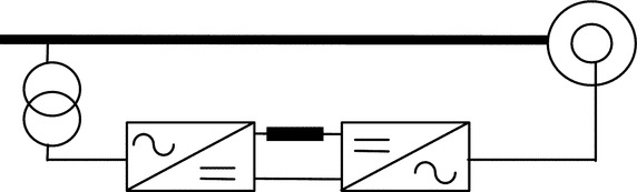
29.3.3.4 Slip Power Recovery (Kramer)
In this type of converter, which is described in Table 29.8, the rotor current of a slip-ring wound-rotor induction motor is rectified and the power then reconverted to AC at fixed frequency and fed back into the supply network. For traditional designs, the low-frequency slip-ring currents are rectified with a diode bridge, and the DC power is then inverted into AC power at mains frequency.
The traditional designs had poor AC mains dip immunity, high torque pulsation, and high levels of low-frequency AC supply harmonics. The latest generation of this type of drive is called the rotor drive and uses PWM-VSI inverters for the rotor and AC supply bridges.
This keeps sine-wave currents in the AC rotor circuits, and the drive has many advantages over traditional circuits including the following:
• Low AC harmonics
• Very high immunity to AC supply dips
• Very cost-effective if a limited speed range is required but still requires a separate starter
• Inherent ability to run at rated speed without electronic circuits
• Converter cost reduced by 2:1 if it uses the ± speed ability to give a speed range
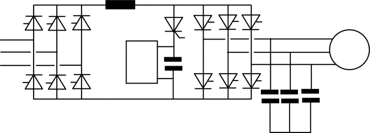
29.3.3.5 PWM-VSI Converter
The availability of power electronic switches with turn-off capability; for example, FETs, BJTs, IGBTs, and GTOs have currently favored drives with voltage-fed PWM converters on induction.
The PWM-VSI drives offer the highest possible performance of all VSDs; refer to Table 29.9. Recent improvements in switching technology and the use of microcontrollers have greatly advanced this type of drive. The inverters are now able to operate with an infinite speed range. The supply power factor is always near unity. Additional hardware is easily added if there is a requirement to regenerate power back into the mains supply. Motor ripple current is related to the switching frequency, and in large drives, the motor may be derated by <3%.
Table 29.9
Drive features
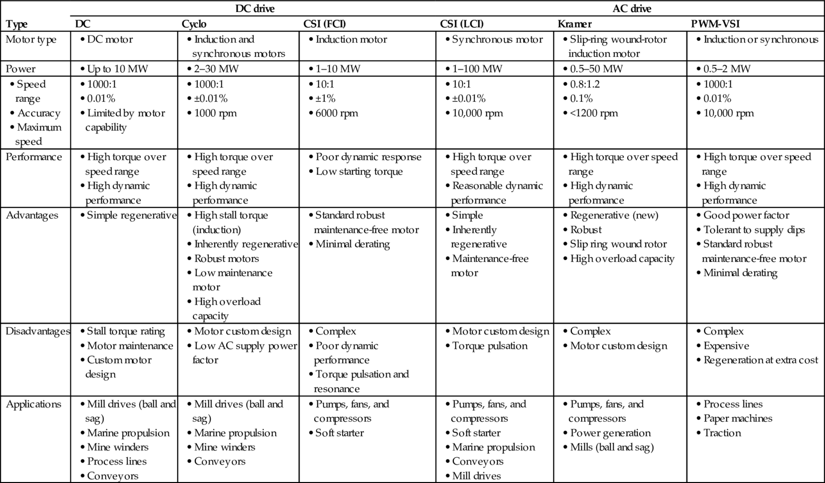
29.3.3.6 Comparison
Table 29.9 summarizes the main features of all types of converter drives discussed above and assesses their merits and drawbacks. It also illustrates typical applications.
29.4 Load Profiles and Characteristics
The way the drive performs is very much dependent on the load characteristics. Here are four load characteristics described.
29.4.1 Load Profile Types
In the literature, four different load profiles have been described, for example, Ref. [3] (Table 29.10). These are the following:
Table 29.10
Load characteristics


1. Torque proportional to the square of the shaft speed (variable torque)
2. Torque linearly proportional to speed (linear torque)
3. Torque independent of speed (constant torque)
4. Torque inversely proportional to speed (inverse torque)
29.4.2 Motor Drive Duty
29.4.2.1 Duty Cycle
The size of the driven motors is generally chosen for continuous operation at rated output, yet a considerable proportion of motor drives is used for duties other than continuous. As the output attainable under such deviating conditions may differ from the continuous rating, fairly accurate specification of the duty is an important prerequisite for proper planning. There is hardly a limit to the number of possible duty types.
In high-performance applications, such as traction and robotics, the load and speed demands vary with time. During acceleration of traction equipment, a higher start-up torque (typically twice the nominal torque) is required; this is usually followed by cruising and deceleration intervals. As the torque varies with time so does the motor current (and motor flux linkage level). The electric, magnetic, and thermal loading of the motor and the electric and thermal loading of the power electronics converter are definite constraints in a drive specification.
Table Table 29.11 categorizes operating duties into eight major types (Ref. [4]).
Table 29.11
Definition of load cyclic duties—VDE0530, in accordance with IEC 34-1
| Duty type | Representation | Description |
| S1: Continuous running duty |  |
Operation at constant load of sufficient duration for the thermal equilibrium to be reached. Specify by indicating “S1” and required output |
| S2: Short-time duty |  |
Operation at constant load during a given time, less than required to reach thermal equilibrium, followed by a rest and deenergized period of sufficient duration to reestablish machine temperatures within 2°C of the coolant |
| S3: Intermittent periodic duty with a high start-up torque |  |
A sequence of identical duty cycles, each including a period of operation at constant load and a rest and deenergized period. In this duty type, the cycle is such that the starting current does not significantly affect the temperature rise |
| S4: Intermittent periodic with a high start-up torque |  |
A sequence of identical duty cycles, each cycle including a significant period of starting, a period of operation at constant load, and a rest and deenergized period |
| S5: Intermittent periodic duty with high start-up torque and electric braking |  |
A sequence of identical cycles, each cycle consisting of a period of starting, a period of operation at constant load, a period of rapid electric braking, and a rest and deenergized period |
| S6: Continuous-operation periodic duty |  |
A sequence of identical duty cycles, each cycle consisting of a period of operation at constant load and a period of operation at no load. There is no rest and deenergized period |
| S7: Continuous-operation periodic duty with high start-up torque and electric braking |  |
A sequence of identical duty cycles, each cycle consisting of a period of starting, a period of operation at constant load, and a period of electric braking. There is no rest and deenergized period |
| S8: Continuous-operation periodic duty with related load/speed changes | A sequence of identical duty cycles, each cycle consisting of a period of operation at constant load corresponding to a predetermined speed of rotation, followed by one or more periods of operation at other constant loads corresponding to different speeds of rotation. There is no rest and deenergized period |
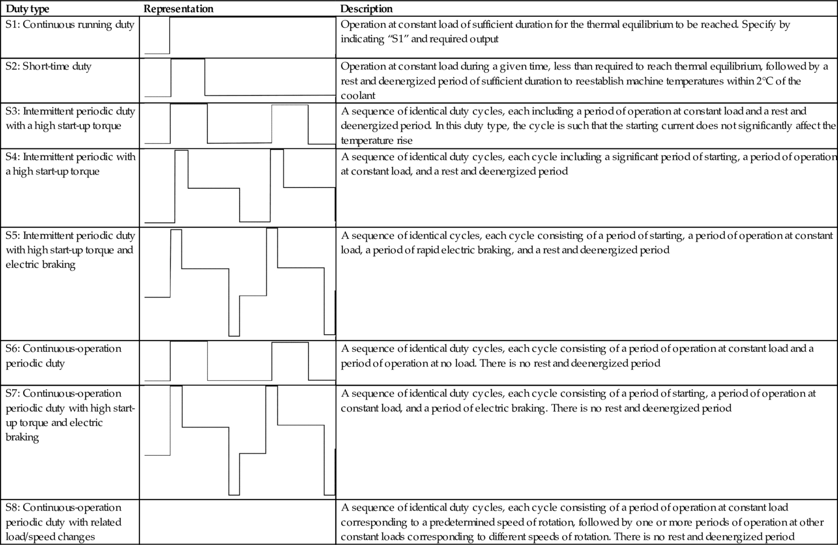
29.4.2.2 Mean Output
Variation of the required motor output during the periods of loaded operation is among the most frequent deviations from the duty types defined in Table Table 29.11. In such cases, the load (defined as current or torque) is represented by the mean load. This represents the root-mean-square (RMS) value, calculated from the load versus time characteristics. The maximum torque must not exceed 80% of the breakdown torque of an induction motor.
If the ratio of the peak torque to the minimum power requirements is greater than 2:1, the error associated with using the RMS output becomes excessive, and the mean current has to be used instead. No such mean value approximation is possible with duty type S2, which therefore necessitates special inquiry.
Careful assessment of duty types S2–S8 reveals that there exist two distinct groups:
1. Duties S2, S3, and S6 permit uprating of motors relative to the output permissible in continuous running duty (S1).
2. Duties S4, S5, S7, and S8 requiring derating relative to the output permissible in continuous running duty (S1).
29.4.2.3 Thermal Cycling
The drive duty cycle also affects the reliability and the life expectancy of power devices. Repetitive load cyclic duty results in additional thermal stresses on power devices. Frequent acceleration and deceleration of drives results in repetitive junction temperature rise and falls at the cyclic duty. The life expectancy of devices is often determined by the maximum allowed number of cycles for a given power device junction temperature rise.
Although this is true for all types of power devices, it is more critical for IGBTs where wire bonds and solder layers are used.
In modern IGBT-based converter design, the maximum junction temperature rise of the IGBTs is limited to a level, which ensures a conservative number of thermal cycles over the lifetime of the drive. Typical junction temperature rise is 30°C for a repetitive cyclic duty (e.g., steel mill) and 40°C for nonrepetitive cyclic duty (e.g., fan pumps).
29.4.2.4 Multiquadrant Operation
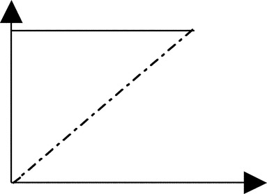
Fully regenerative electric VSDs offer a rapid regenerative dynamic braking in both forward and reverse directions. Operation in motoring implies that torque and speed are in the same direction (QI, III). In regenerative braking, the torque is opposite to the speed direction (QII and IV), and the electric power flow in the motor is reversed. (See Fig. 29.2.)
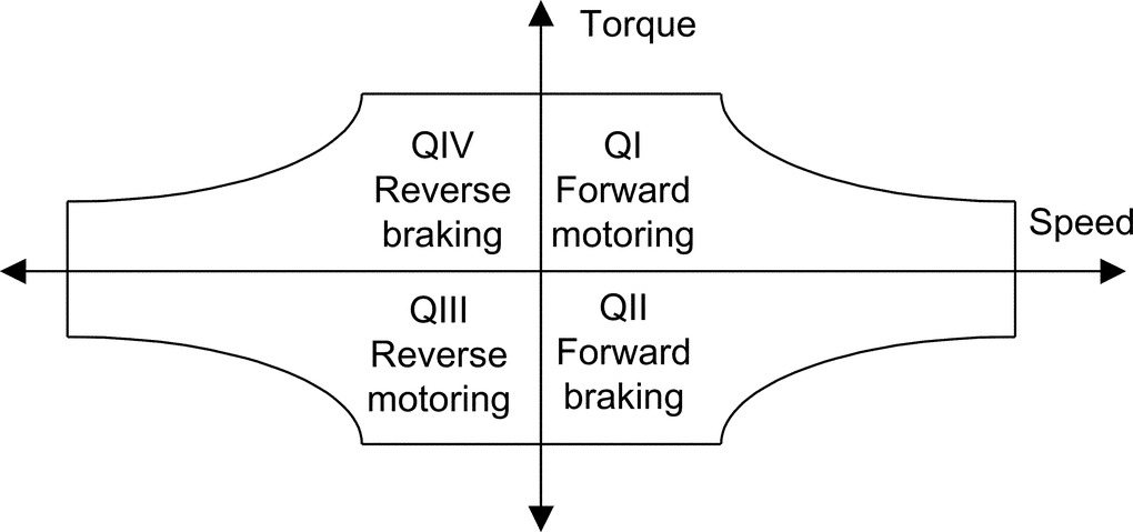
Positive power flow of electric energy means that electric power is drawn from the power supply via the power electronics converter by the motor, while negative power flow refers to electric power delivered by the motor in the generator mode to the power electronics converter. This could be regenerated back to the supply or dissipated as a heat in the dynamic brake dissipative mechanism.
For regenerative drive, the power electronics converter has to be designed to be able to handle bidirectional power flow. In low and medium power converter (say <500 kW) with slow dynamic braking demands, the generated power during the braking period is interchanged with the strong filter capacitor of power electronics converter, or DC (dynamic) braking is used.
29.4.2.5 Dynamic Braking Energy
There exist two types of energy stored in VSD, which need to be dealt with during dynamic braking:
• Inertia or kinetic energy loads: Typically moving (rotating or linear) machines. These would decelerate naturally to rest. Braking can speed up the process cycle for the sake of productivity.
• Mass or potential energy loads: Typically hoists or lifts—which would run on or even accelerate. Braking must apply full power to maintain constant speed while the load is lowered.
The drive losses, mechanical resistance, and the transmission efficiency, work in favor of deceleration, reducing the braking power demand. The energy regenerated by potential energy loads depends on maximum power and both the overrun time and the decelerating time.
The braking time and the duty cycle time are decided by the requirements of the process system, but note particularly the effect of varying the braking duty cycle time and the deceleration time.
For DC injection braking, the kinetic energy of the motor-load system is converted to heat in the motor rotor. For fast and frequent generator braking, the power electronics converter has to handle the generated power either by a controlled dynamic brake chopper (with braking resistor) or through bidirectional power flow. The power losses in the converter can assist in dynamic braking.
For a fast speed response, modern VSDs may develop a maximum transient torque up to the base speed and maximum transient power up to a maximum speed, provided that both the motor and the power electronics converter can handle these powers. For a 200 kW dynamometer drive application, a rapid change of torque from full positive torque to full negative torque is required in <10 ms.
29.5 VSD Topologies
In this section, drive topologies are classified according to the motor they employ. Various publications dealt with this subject, for example, Refs. [3,5]. The most common motors are illustrated in Fig. 29.3.

29.5.1 DC Motor Drives
Until recently, the DC motor drive was the most commonly used type of electric VSD, with only very few exceptions, and is the least expensive. The mechanical commutator is an electromechanical DC-to-AC bidirectional power flow power converter, as the currents in the rotor armature coils are AC while the brush current is DC. The DC drive is well-known, well proved, and widely applied; yet, its popularity is in relative decline due to the emergence of the more robust, lower cost squirrel-cage induction motor drive.
Unfortunately, the mechanical commutator though not bad in terms of losses and power density has serious commutation current and speed limits and thus limits the power per unit to 1–2 MW at 1000 rpm and may not be accepted at all in chemically aggressive or explosion-prone environments. The application of the DC drive has been restricted to hazardous areas due to the very limited availability of flameproof DC machines. Commutator and brush maintenance is difficult in such environments. Furthermore, continuous sparking at the brushes is virtually inevitable at full load output.
Due to the inherent ease of speed control of the separately excited DC machine, DC drives found popularity in early electric drive applications, by varying the applied armature voltage. This variable armature voltage is simply generated by phase-controlled rectification, and this technique has now almost entirely replaced the Ward-Leonard systems previously used.
The AC/DC converter offers a variable DC voltage, which is capable of four-quadrant operation (positive and negative DC voltage and DC current output). Permanent magnet-excited brushed motors have been used in numerous applications for some time, particularly in nonregenerative drive applications.
Motor output torque is approximately proportional to armature current, and motor speed is approximately proportional to converter output voltage. Speed control by sensing armature voltage is therefore feasible giving an accuracy of around 5%.
Provided the motor excitation is kept constant, the DC drive power factor is proportional to motor speed. Since most pumps, compressors, and fans demand a torque proportional to the square of speed, constant excitation systems are used and so the above relationship applies.
A typical power factor, at maximum rated speed for a DC drive, is 0.85. This relationship applies to many other types of electric drives.
If a slow dynamic response is satisfactory, regeneration to the mains supply is achieved either by reversing the motor field or armature connection. Alternatively, regeneration with faster response is achieved by connecting another thyristor bridge in antiparallel with the main bridge. In this case, fast response is possible with changeover time of <15 ms between full torque motoring to full torque regenerating. The 6-pulse drive configuration is acceptable for powers up to 1 MW. This limitation arises not from any semiconductor device limitation but is due to AC line current harmonics the converter generates.
A force-commutated or “chopper” converter for DC motors uses the principle of variable mark-space control using a thyristor or transistor solid-state switch. With a diode front-end converter, a fixed, smoother DC supply is derived from the mains by uncontrolled rectification and rapidly applied, removed, and reapplied to the machine for adjustable intervals, thus applying a variable mean DC voltage to the DC motor; refer to Fig. 29.4B.
This type of DC drive has the advantage of high (near unity) power factor at all motor speeds and much reduced harmonic spectrum.
29.5.2 Induction Motor Drive
29.5.2.1 Squirrel Cage Induction Motor
Squirrel-cage induction motors are simpler in structure than DC motors and are most commonly used in the VSD industry. They are robust and reliable. They require little maintenance and are available at very competitive prices. They can be designed with totally enclosed motors to operate in dirty and explosive environments. Their initial cost is substantially less than that of commutator motors, and their efficiency is comparable. All these features make them attractive for use in industrial drives.
The three-stator windings develop a rotating magnetic flux rotating at synchronous speed. This speed depends on the motor pole number and supply frequency: the rotating flux intersects the rotor windings and induces an EMF in the rotor winding, which in turn results in circulating current. The rotor currents produce a second magnetic flux, which interacts with the stator flux to produce torque to accelerate the machine. As the rotor accelerates, the induced rotor voltage falls in magnitude and frequency until an equilibrium speed is reached. At this point, the induced rotor current is sufficient to produce the torque demanded by the load. The rotor speed is slightly lower than the synchronous speed by the slip frequency, typically 3%.
In order to ensure constant excitation of the machine, and to maximize torque production up to the base speed, the ratio of stator voltage to frequency needs to be kept approximately constant.
Induction motor drive has three distinct operating regions:
(a) Constant torque: The inverter voltage is controlled up to a maximum value limited by the supply voltage. As the motor speed and the voltage are increased in proportion, constant V/F, the rated flux linkage is maintained up to the base speed. Values of torque up to the maximum value can be produced at speeds up to about this base value. The maximum available torque is proportional to the square of the flux linkage. Typically, the induction motor is designed to provide a continuous torque rating of about 40%–50% of its maximum torque.
(b) Constant power: For higher speed, the frequency of the inverter can be increased, but the supply voltage has to be kept constant at the maximum value available in the supply. This causes the stator flux linkage to decrease in inverse proportion to the frequency. Constant power can be achieved up to the speed at which the peak torque available from the motor is just sufficient to reach the constant power curve. A constant power speed range of 2–2.5 can usually be achieved. Within this range, the motor frequency is increased until at maximum speed.
(c) Machine limit (pullout torque): Once the machine limit has been reached, the torque falls off in proportion to the square of motor frequency. Operation at the higher end of this speed range may not be feasible as the motor power factor worsens. This in turn results in a higher stator current than the rated value. The motor heating may be excessive unless the duty factor is low.
Induction motors are used in applications requiring fast and precise control of torque, speed, and shaft position.
The control method widely used in this type of application is known as vector control, a transient response at least equivalent to that of a commutator motor can be achieved.
The voltage, current, and flux linkage variables in this circuit are space vectors from which the instantaneous values of the phase quantities can be obtained by projecting the space vector on three radial axes displaced 120 degrees from each other. The real and imaginary components of the space vectors are separated, resulting in separate direct and quadrature axis equivalent circuits but with equal parameters in the two axes.
Changes in the rotor flux linkage can be made to occur only relatively slowly because of the large value of the magnetizing inductance of the induction motor. Vector control is based on keeping the magnitude of the instantaneous magnetizing current space vector constant so that the rotor flux linkage remains constant. The motor is supplied from an inverter that provides an instantaneously controlled set of phase currents that combine to form the space vector, which is controlled to have constant magnitude to maintain constant rotor flux linkage. The second component is a space vector, which is in space quadrature with the instantaneous magnetizing current space vector. This component is instantaneously controlled to be proportional to the demand torque.
To the extent that the inverter can supply instantaneous stator currents meeting these two requirements, the motor is capable of responding without time delay to a demand for torque. This feature, combined with the relatively low inertia of the induction motor rotor, makes this drive attractive for high-performance control systems.
Vector control requires a means of measuring or estimating the instantaneous magnitude and angle of the space vector of the rotor flux linkage. Direct measurement is generally not feasible. Rapid advances are being made in devising control configurations that use measured electric terminal values for estimation.
29.5.2.2 Slip-Ring (Wound-rotor) Induction Motor Drive
Wound-rotor induction motors with three rotor slip rings have been used in adjustable speed drives for many years. In an induction motor, torque is equal to the power crossing the air gap divided by the synchronous mechanical speed. In early slip-ring induction motor drives, power was transferred through the motor to be dissipated in external resistances, connected to the slip-ring terminals of the rotor. This resulted in an inefficient drive over most of the speed ranges. More modern slip-ring drives use an inverter to recover the power from the rotor circuit, feeding it back to the supply system.
The speed of slip-ring induction motor can be controlled by the following:
• Stator frequency control as with a cage rotor machine.
• Rotor frequency control.
• Rotor resistance control.
• Slip energy recovery (Kramer system). For capital cost reasons, the last two are commonly used.
Addition of rotor resistance especially for starting large induction motors is well-known. The basic effect produced by adding rotor resistance is to alter the speed at which maximum motor torque is developed. Unfortunately, power dissipation as heat in the rotor resistance bank takes place; earlier means to overcome this shortcoming were to convert the rotor power to DC and feed a DC motor on the same shaft. The rotor slip energy, when running at reduced speed, is therefore reconverted to mechanical power. This is the “Kramer” system. The disadvantages of this approach were the extra maintenance and capital costs.
The static Kramer system overcomes these shortcomings by replacing the DC machine with a line-commutated inverter that returns the slip energy directly to the AC line, either directly (on lower power systems) or via a transformer. A key advantage of the Kramer drive system is that the slip-energy recovery equipment (DC machines or static inverter) needs only be rated for a fraction of the maximum motor rating. This is true when a small speed range is required and provided that a separate means is provided of starting the motor. This is because the motor rotor current is proportional to torque and the rotor voltage inversely proportional to speed.
Naturally, if the slip-energy recovery network can be rated to withstand full rotor voltage (developed at standstill), a controlled speed range of zero to maximum could be achieved. However, this is generally only feasible on smaller motors (below 2000 kW) where the rotor voltage is sufficiently low for an economic inverter package. Secondly, if a full speed range is needed, the slip-energy recovery network has to be rated at full motor power, so static Kramer drives become uneconomic for wide speed ranges. The overall system power factor would be very low for a wide speed range system.
For the above reasons, Kramer drives are very suitable for high-power drives (>200 kW) where a small speed range is required. Pump and fan drives present therefore good economic applications. Kramer drives have also been used for low-speed-range endurance dynos using the recovery system to control torque of induction generator. As with all line-commutated converters and inverters, current harmonics are produced, and these can be reduced to acceptable values. However, as the slip-energy recovery network is only power-rated in direct proportion to the speed reduction required (assuming constant load torque), the magnitudes of the harmonic currents generated are proportionally less than with drives where the solid-state converters have to handle the whole drive power. Harmonics of the rotor rectifiers are transmitted through the rotor and appear as noninteger harmonics in the main supply.
The main disadvantages of the slip-ring induction motor drive are (a) the increased cost of the motor in comparison with a squirrel cage, (b) the need for slip-ring maintenance, (c) difficulty in operating in hazardous environments, (d) the need for switchable start-up resistors, and (e) the poor power factor compared with other types of drive.
29.5.3 Synchronous Motor Drives
To understand the way the synchronous machine operates, let us assume that the induction motor were to rotate at the synchronous speed by an external means. Under this condition, the frequency and magnitude of the rotor currents would become zero. If an external DC power supply were connected to the rotor winding, then the rotor would become polarized in a similar way to a permanent magnet. The rotor would pull into step with the air-gap-rotating magnetic field, generated by the stator but lagging it by a small constant angle referred to as the load angle. The load angle is proportional to the torque applied to the shaft, and the rotor keeps rotating at synchronous speed, provided that the DC supply is maintained to the rotor field winding. The magnetic flux produced by the rotor winding intersects the stator windings and generates a back EMF, which makes the synchronous motor significantly different from the induction motor.
As with the induction motor drive, the requirement is to keep the ratio V/F constant (i.e., varies both the stator frequency and applied voltages in proportion to the desired motor speed).
The supply bridge converter is phase-controlled generating an adjustable DC current in the DC link choke. To generate maximum torque from the synchronous motor, this current is switched into the motor stator windings at the correct phase position with respect to rotor angular position as detected by the position sensor by the inverter bridge. When running above about 10% speed, the back EMF generated by the synchronous motor is sufficient to commutate the current into the next arm of the inverter bridge. So, as this type of inverter is machine (motor)-commutated, the inverter configuration is merely that of a conventional DC drive. The complexity, expense, and limited power capability of the force-commutated circuitry is therefore avoided.
The motor back EMF is insufficient for thyristor commutation at low speeds. The technique here, therefore, is to rapidly phase back the supply converter bridge to reduce the DC link current to zero and after a short delay (to ensure that all thyristors in the machine bridge are turned off) reapply DC current when the correct thyristor trigger pattern has been reestablished. As the motor speed and thus back EMF increase to a value sufficient for machine commutation, changeover to continuous DC link current operation is effected.
During the starting mode, the correct inverter bridge firing instant is determined by rotor position sensor, which is mounted on the motor shaft whose angular position is detected by opto or magnetic probes. When in the machine-commutated mode, sensing of stator voltage is used. To develop maximum torque in the low speed or pulsed mode, angular rotor position sensing is necessary. However, if less than full load torque availability at low speed can be tolerated, the inverter system can be set to produce a low fixed frequency in the pulsed mode. This frequency is then increased, as motor rotation is detected (either in steps or on a preset ramp rate) until sufficient back EMF is generated to facilitate changeover to the voltage-sensing mode.
As previously stated, the key advantage of this type of drive is that all thyristor devices are line- or machine-commutated. Expensive and complex forced commutation circuitry is avoided, and fast turn-off thyristors are unnecessary. Inverter systems of this type can therefore be built at very high powers, up to 100 MW. Also, as a result of avoiding force commutation, converter efficiency is high.
The thyristors in the machine inverter bridge must be triggered at such an angle to give sufficient time for commutation from one device to the next. This results in the synchronous motor operating at a high leading power factor of around 0.85. However, as far as the mains supply is concerned, the total drive has the characteristics of a DC drive where power factor is proportional to speed.
Another important characteristic of this type of drive is that it is inherently reversible and regenerative. For regenerative operation, the inverter bridge is triggered in the fully advanced position, so in effect, it becomes a plain diode bridge. A DC output voltage, approximately proportional to motor speed, is therefore generated at the DC side of the supply converter bridge. This converter bridge is now triggered in the regenerative mode thus returning power to the supply system. Reversing operation is achieved by altering the sequence in which the thyristors in the inverter bridge are triggered.
This type of drive is widely applied over a wide power range as it embodies an efficient brushless motor and relatively simple and efficient converter. At lower powers, say below 30 kW, permanent-magnet synchronous motors are more common.
Unlike the induction motor, the synchronous type requires two types of converter: the first for main power conversion while the second is low power for field excitation. The field converter feeds the rotor exciter winding through slip rings and brushes, or alternatively, a brushless exciter can be used. A coordinated control of the two converters provides for active power and reactive power control and for efficient wide speed range control in high-power applications.
For high-power applications, synchronous motors are preferred because of the ability to control reactive power flow through appropriate control of excitation. Synchronous motors tend to have wider speed range and higher efficiency. However, synchronous motors are generally more expensive than induction motors.
With modern high-power PWM-VSI drives, synchronous motor can be driven for same inverter with vector control methods.
29.5.4 Special Motors
Motors under this category employ power electronics converters for normal operation. Generally, this type of motor has a large number of phases in order to limit torque pulsation and self-start from any rotor initial position. This is a new breed of motors, which can be fed through a unipolar or bipolar current. Also they have singly salient or doubly salient magnetic structures with or without permanent magnets on the rotor.
29.5.4.1 Brushless DC Motor Drive
This type of machine has a similar construction to a standard synchronous machine, but the rotor magnetic field is produced by permanent magnet material. A position sensor is used to ensure synchronism between the rotor position and the stator magnetomotive force (MMF) via drive signals to the inverter. The use of new magnet materials characterized by high coercive force levels has reduced magnet sizes and largely overcome the demagnetization problem. The absence of the field copper losses improves the machine efficiency.
As the permanent magnet is the source for excitation, the brushless DC motor (BDCM) can be viewed as a constant flux motor. A limited amount of flux weakening can be achieved by increasing the load angle of the stator current. Achieving a useful constant power range is not usually practical with this type of motor. A large demagnetizing component of stator current would be required to produce a significant reduction in magnet flux, and this would increase the stator loss substantially.
The required base torque determines the motor size, and the losses are essentially independent of the number of stator turns. At speeds up to the base speed of the constant power range, the efficiency of the motor is essentially the same as for one designed for rated voltage at base speed. For operation above base speed, the stator current from the inverter is reduced in inverse proportion to the speed. This mode of operation in the high-speed range reduces the dominant stator winding losses relative to a machine in which the flux is reduced and the current kept constant. The losses in the inverter are, however, increased due to its higher current rating. For an electric road vehicle that must carry its energy store, the net energy saving may be sufficiently valuable to overcome the additional cost of the larger inverter. A further advantage of this approach is that, if the DC supply to the inverter is lost, the open-circuit voltage applied to the inverter switches will be within their normal ratings.
The BDCM has higher volumetric power density compared with other types of motors (induction or synchronous). They are particularly suited for the high values of acceleration required in drives (e.g., machine tools). They are often operated with high acceleration for a short time followed by a longer period of low torque. At such low values of load factor, the cooling capability is frequently not a limitation. The major interest is in obtaining the maximum acceleration from the motor. The short-term stator current of a BDCM is limited to the value required for magnet protection. These values of acceleration are significantly higher than that can be achieved with either induction or DC motors of similar maximum torque rating.
29.5.4.2 Switched Reluctance Motor Drive
This motor can be regarded as a special case of a salient synchronous machine in which the field MMF is zero and the torque is produced by reluctance or saliency action only. The rotor has no winding. The switched reluctance motor (SRM) drive needs an inverter whose frequency is locked to the shaft speed, but since the torque is linearly proportional to the square of the stator current, the use of unidirectional current involves little sacrifice in performance.
Generally, the use of position sensors in the SRM and BDCM is something of a disadvantage in both cases. The SRM does not require permanent magnets, which can cost and may involve demagnetization risks and limit top speeds due to centrifugal forces. The SRM hence has a simpler construction and is more robust. However, the need to magnetize the motor from the AC side adds to inverter costs and may increase peak current levels significantly, hence raising stator copper losses.
Switched-reluctance synchronous motors have a cylindrical stator with three AC windings and a solid rotor (without any winding) with a moderate orthogonal axis magnetic saliency up to 4 (6) to 1. High magnetic saliency is obtained with multiple flux barriers. The conventional SRMs are to some extent (up to 100 kW) used in low-dynamics VSDs with open-loop speed control, as the speed does not decrease with load. Consequently, the control is simpler than with induction motors.
The main drawback of the conventional SRD is the low motor power factor and the relatively poor torque density, which leads to a higher kVA rating of the power converter (~20%). The main advantage of the synchronous reluctance motor over the induction motor of similar rating is the higher efficiency. Compared with the squirrel-cage induction motor, the rotor loss is small or negligible in synchronous reluctance machines. If the saliency ratio is sufficient to produce a power factor equal to that of the induction motor, the stator winding loss will be the same. Also, the stator iron losses will be similar for the two motors.
The reluctance motor is capable of operation in the constant power mode of operation. As for all AC drives, when the supply voltage limit is reached above the base speed, the flux linkage is reduced in inverse proportion to the shaft speed, and the torque is inversely proportional to speed squared.
29.5.4.3 Linear Motors
There are applications in which linear motion, as opposed to rotational, is required. A linear machine has the same operating principles as those applied to all other rotating machines. The PWM-VSI converters and motor control principles discussed in this chapter are also applicable to this type of motor.
There are two types of linear motors:
• LSM—linear synchronous motor with permanent magnetic excitation
The LSM type has the following advantages over the LIM:
• More responsive control
• Higher efficiency
The disadvantages of LSM are the following:
• Very accurate position feedback is required.
• The use of PM—expensive and heavy.
Transport, material handling, and extrusion processes are a few examples in which linear motors have successfully been employed.
29.5.4.4 Stepper Motors
Stepper motors are either built in a similar manner to BDCM, with permanent magnets embedded in or bonded to the rotor or a rotor with no magnets. The latter type is made of a ferrite magnetic material, and its circumference is cut to form a number of slots, forming teeth lengthwise to the rotor axis.
Torque production can be based on (a) magnetic reluctance (as in SRM), (b) magnetic attraction (as in BDCM), or (c) both magnetic reluctance and attraction.
Stepper drives do not offer dynamic speed control, and the main action is to accelerate at full torque to full speed, maintain the speed, and decelerate at full torque. In comparison with the reluctance-type stepper motor, the permanent magnet type offers greater torque for a given speed, particularly at start and low speeds.
Most drives incorporate controllers with connections for a communications link for supervisory control by PLC, hard-wiring connectors for analog/digital inputs and outputs, and some are equipped with software for communications with a computer or handheld keypad. Table 29.12 lists typical options.
Table 29.12
Control features for servo and stepper motor drives (Ref. [6])
| Control features | Servo drive | Stepper drive |
| Acceleration/deceleration time | Adjustable | Accelerate at maximum torque, time is dependent on maximum torque and inertia |
| Maximum speed | Part of the motor specification | Part of the motor specification |
| Speed control | Permit a range of speed settings | Not necessarily available |
| Torque control | Many offer speed and torque control | Always operate at maximum torque |
| Auto-tuning | A feature of some servo drive | Not applicable |
| Reversing | Commonly available by digital control signal | Commonly available by digital control signal |
| Zero speed clamp | Applies full torque to hold the position constant | Applies full torque to hold the position constant |
| Dynamic braking | Controlled deceleration, may require dissipative brake resistor | Usually standard |
| Regenerative braking | Dedicated circuit for controlled braking | Not applicable |
| Travel limits | Definition of travel limits in the forward and reverse directions | Standard |
| Jog or inch | Digital command to “jog” one step (with defined distance) | Optional feature |
| Closed-loop configuration | Most drives accept external signals for closed-loop control | Most drives accept external signals for closed-loop control |
| Programming functions | Many drives incorporate programming functions as in PLCs, reset all functions to default states, return to a home position, enable or disable repetition or a preset sequence, select a particular set of control inputs, increased or decreased speed, change the torque boost, etc. | |

Unlike above motor drives, the stepper motor can achieve precise position control without the need for any external feedback.
29.5.4.5 Actuators
Actuators are widely used in industry, primarily for positioning tasks. Their designs are based on all sorts of force-producing principles. Ref. [7] describes several types of direct drive electric actuators, including (a) the DC actuator (moving coil type), (b) induction actuators, (c) synchronous actuators (moving magnet DC type), (d) reluctance actuators, and (e) inductor actuators (polarized reluctance type).
Electric actuators are used increasingly in control systems and automated electromechanical equipment. Typical specification factors include range of motion, type of motion (linear or rotary and stepwise or continuous), resolution needs, speed of response, environmental conditions, supply conditions, allowable electromagnetic noise emission level, need for integrated position and velocity sensors, maintenance needs, eligibility, cost, peak, and continuous torque.
The main demands of industry for high-performance systems are the following:
(a) A convenient supply and low power consumption
(b) Reliability and robustness
(c) Low initial cost and maintenance
(d) Fast response
(e) Linear “torque-excitation” characteristics
29.5.4.6 Integrated Motors
The integral motor consists of a standard AC motor with an integrated frequency inverter and EMC filter. It is robust and specified for reliable operation and often designed to handle rough working conditions, including ambient temperature −25°C to −40°C and dusty, corrosive, and humid environments (enclosure IP55). This type of drive uses a standard induction motor with the AC/AC converter integrated in the motor frame often as a separate converter box mounted directly above the motor frame in place of the terminal box. The power popularity of this type of drive is limited to 0.5–7.5 kW.
This type of motor offers the following advantages:
• Save space by eliminating the need for a separate controller
• Reduce installed costs because cabling between motor and converter is eliminated
• Eliminate motor problems caused by high voltage transient due to output cable capacitance
• Minimize EMC due to high dV/dt
The integrated drive includes most features including start, stop, forward, reverse, speed and torque controls, and controlled acceleration and deceleration.
29.6 PWM-VSI DRIVE
In recent years, the popularity of PWM-VSI has increased beyond recognition. Its dynamic performance and controllability is better than the DC drive. Its power range has extended to areas dominated for years by traditional solutions such as the cycloconverter and LCI drives.
29.6.1 Drive Comparison
Table 29.13 shows a direct comparison between the cycloconverter, LCI, and PWM-VSI drives. The DC drive and the slip-power recovery converter type are not listed because AC drives have already replaced DC drives in most applications due to low maintenance and better reliability of AC motors. Slip recovery is only suitable for applications with a limited speed range and requires a slip-ring wound rotor.
Table 29.13
Drive comparison
| Control features | Cyclo | LCI | PWM-VSI | Matrix |
| Speed | Limited | Wide | Wide | Wide |
| Dynamic response | Excellent | Good | Excellent | Excellent |
| Torque pulsation | Low | High | Very low | Very good |
| Power factor at low speed | Poor | Poor | Very good | Very good |
| Stability | Good | Moderate | Very good | Very good |
| Motor | Custom | Custom | Standard | Standarda |
| Regeneration | Inherent | Inherent | Needs extra hardware | Inherent |
| Volumetric power density | Moderate | Good | Very good | Excellent |
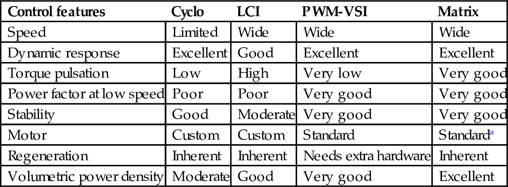
a The AC output voltage of the matrix converter is always less than the input voltage—derating is expected, or a larger frame size is required.
In comparison with the cycloconverter and LCI current-source converter drives, the PWM-VSI drive offers the following advantages:
• Smooth torque/speed control over full speed range (0–200 Hz)
• High volumetric power density
• Ride through of dips in supply voltage
• Use of standard motors (squirrel-cage induction motor or synchronous motor)
• Improved AC supply power factor over full speed range
• Reduced cabling and transformer size and cost in comparison with cycloconverters
• No significant torque pulsation
• Lower noise level
• Low maintenance
29.6.2 Medium Voltage PWM-VSI
The maximum power rating of LV VSD is limited by practical current ratings of power components such as motor, cable, and transformer (typically 1500 A), giving a limit of about 2 MVA at 600 V. At this rating, motor manufacturers always prefer an MV machine design—significant saving and improved thermal performance of power components can be achieved by operating at medium voltages instead of low voltages. Many VSD applications will benefit from the availability of economic MV alternatives.
When adequately rated high blocking voltage devices are available, a simple two-level inverter or alternatively three-level neutral-point clamp (NPC) has always been the choice to meet required output voltages. These topologies offer a simple and cost-effective solution.
Series connection of power devices is the traditional solution for high-power high-voltage thyristor-based drives. This approach is perceived to be complex with fast-switching IGBTs because of simultaneous switching and correct static and dynamic voltage sharing of series devices.
The “multilevel” inverter drive is seen to offer a better solution for high-power, high-voltage inverter drive. The output waveform is high quality, even at very high modulation frequencies, which inherently results in lower harmonic content in the output voltage waveform (less losses, less torque pulsation, and lower insulation voltage stresses).
Ref. [8] and Fig. 29.5 categorize MV converter topologies as follows:

(A) Series-connected two level (SC2L)
(B) Three-level neutral-point clamp (3LNPC)
(C) Multilevel: diode-clamped multilevel (DCML) and capacitor-clamped multilevel (CCML)
(D) Isolated series H-bridge (ISHB) (Table 29.14)
Table 29.14
Comparison between different MV converter stack topologies

29.6.3 Control Strategies
Several control techniques can be found in the VSD industry; refer to Fig. 29.6. These are the following:

• Open-loop inverter with fixed V/Hz control
• Open-loop inverter with flux vector control
• Closed-loop inverter with flux vector control (induction motor)
Table 29.15 summarizes the main features, advantages, and disadvantages of each technique.
Table 29.15
Comparison between various control methods used in VSD

29.6.4 Communication in VSDs
The use of a high-speed advanced digital communication (fieldbus) to build industrial automation system for real-time control or simply for data logging has become well established in modern industries. Digital communication resulted in replacing wiring looms with a digital serial network; this resulted in a lower cost installation and a more reliable solution. Over the last few years, many industrial fieldbuses emerged, and end users, system integrators, and original equipment manufacturers (OEMs) chose the optimum system for their applications.
A fieldbus is a digital communication system that allows a control system to exchange data with remote sensors, actuators, and drives using a single communication link. The major benefits seen are (a) reduced installation and cabling cost and better overall immunity of the system. Both factors result in a more reliable operation and reduced maintenance costs.
There exist two main types of network:
(a) Centralized network—requires a network master controller, typically a PLC. The master device is entirely responsible for controlling communications over the network, while the slave devices tend to be “dumb” devices with no local intelligence.
(b) Decentralized network—which requires some local intelligence at each node but no overall master device. This is ideal for real-time application environment, as all nodes are effectively running in parallel.
Most modern VSDs are equipped with hardware and software, which enable local and remote communication with plant automated system via a fieldbus system. The most popular fieldbuses are Profibus, Interbus, Ctnet, Sercos, Worldfib, and DeviceNet.
29.6.5 PWM Techniques
Different PWM techniques have been employed in PWM-VSD converters. Fig. 29.7 identifies the most commonly used techniques.
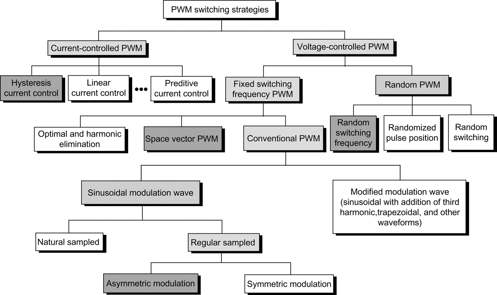
29.6.6 Impact of PWM Waveform
29.6.6.1 PWM Voltage Waveform
Fast switching of IGBTs (typically <1 μs) results in high dV/dt, typically 3–5 kV/μs, and possible voltage overshoot at turn-off that can last for a few microseconds. The fast rate of rise/fall of voltage combined with high peak voltage at the turn-off results in a premature failure of motors and EMC. Refs. [9–11] deal with the effect of PWM waveforms of VSD.
The following is a brief summary of the effect of the unfiltered waveforms.
29.6.6.2 Effect on Motor
• Premature insulation failure due to partial discharge as a result of peak voltage, high dV/dt, and high frequency.
• Motor shaft voltage that forces current into the shaft bearing, leading to early bearing failure.
• Motor stray capacitance (between windings and earthed frame) leads to earth-current flow caused by high dV/dt.
• High dV/dt creates nonuniform distribution of voltage across the winding, with high voltage drop across the first few turns and consequential failures.
• In a large motor, voltage differential on the frame is likely to develop in spite of protective earthing of the motor. More than one earthing point is needed.
29.6.6.3 Effect on Cables
• Voltage-doubling effect at the rising/falling edges of voltage waveform due to wave propagation in long cables [9].
• Earth-current flows in cable stray capacitance due to dV/dt.
• Restriction on cable type used and earthing methods employed.
• Cable type (armored, screen, and multicore).
• Likelihood of cross talk with other surrounding cables running in parallel.
• For PWM drives, the cost of cabling is likely to be significant due to special requirements of cables and termination methods employed.
29.6.6.4 Effect on EMC/Insulation/Earthing
• Inductive and capacitive couplings between live components and earth result in common-mode and differential-mode noise. This could lead to malfunctioning of nearby sensitive equipment.
• The voltage to earth applied on drive components pulsates at the switching frequency, adding voltage stresses (worst at low speeds and low modulation index). This poses additional insulation requirements on main power components (motor, cable, output filter, and transformer).
• A fourth wire may be required between the motor frame and the converter virtual earth so that a low impedance path is provided for the motor earth current.
• Strict rules must be observed when cabling and earthing.
29.6.6.5 Motor Insulation
High peak voltages can be experienced at the motor terminals especially when long cable is employed (10–100 m depending on the size of motor). This is usually caused by voltage-doubling phenomena of a transmission line with unequal line and load impedance. Motor line voltage can reach twice the DC link voltage with long cables.
Fast voltage rise times of 5000 V/μs can be measured at the motor terminals. Under this condition, the motor insulation becomes stressed and can lead to a premature breakdown of a standard motor insulation. When motor fails due to insulation stress caused by high peak voltage and fast voltage rise times, failure occurs in the first turn as phase-to-phase short or phase-to-stator short. The highest voltage is normally seen by the first turn of the winding.
Standard motor capabilities, established by the National Electrical Manufacturers Association (NEMA) and expressed in the MG-I standard (part 30), indicate that standard NEMA type B motors can withstand 1000 V peak at a minimum rise time of 2 μs (500 V/μs). Ref. [10] describes the effect of PWM inverter waveform on motor insulation in more detail.
Partial discharge
The phenomena that starts deterioration of the motor insulation is called partial discharge (PD). When electric stresses in insulation voids exceed the breakdown voltage of the air, a partial discharge occurs. Successive PDs destroy the insulation slowly.
Voltage strength between phase to phase and phase to frame
Both NEMA and IEC are proposing (a) maximum 1000 V at rise time <2 μs and (b) a maximum rate of rise of 500 V/μs. It is believed that low-voltage standard motors can withstand a lot larger voltage stresses than specified by NEMA and IEC, possibly up to 1300 V, almost regardless of the rise time.
Voltage strength between turn to turn
In low-voltage AC motors, the conductor insulation is designed for 245 V RMS (350 V peak). The insulation strength is however higher depending on the impregnation method.
29.6.6.6 Bearing Current
Bearing current and shaft voltages under 50/60 Hz sine-wave operation has been recognized since 1924. The bearing impedance characteristics largely determine the resulting bearing current that will flow for a given shaft voltage [11].
The rotating machines have three basic sources of shaft voltage. These are the following:
• Electromagnetic induction from the stator winding to the rotor shaft (due to small asymmetries of the magnetic field in the air gap that is inherent in a practical machine design). The design limit is <1 V RMS.
• Electrostatic coupled from internal sources: such as voltage in motors where rotor charge accumulation may occur (belt-driven coupling and ionized air passing over rotor fan blades).
• Electrostatic coupled from external sources such as PWM inverter. The presence of high dV/dt across the stator neutral to frame ground causes a portion of the voltage to ground due to capacitor divider action. The presence of PWM-related voltage components is undesirable and leads to a premature bearing failure.
• The fundamental cause of the shaft voltage is magnetic asymmetry between the stator and the rotor or possibly a phase shift of the motor voltage waveform. System ground may also contribute to this condition through unbalance system voltage.
• NEMA-500 recommends the consideration of insulated bearing for motor frame of certain sizes.
29.6.6.7 Electromagnetic Compatibility
The main sources of electromagnetic emission of PWM-VSI drives are described in [12] as follows:
AC/DC converter: Supply harmonics caused by supply bridge rectifier (from 100 Hz to 2.5 kHz): as already explained, the input bridge circuit with an SCR or diode bridge is a source of supply harmonics in the input current.
DC/AC inverter: Harmonics caused by the switching of the inverter bridge (from 3 kHz to 20 MHz): the inverter bridge uses fast-switching devices to create PWM voltage output. The inverter is a source of a wide band of frequencies, typically extending from the basic switching frequency (usually several kilohertz) to the radio high-frequency bands at 20 MHz. The radio frequency current spreads out into both the supply and motor connections. An EMC filter is often used to limit the spread of high-frequency harmonics into the supply.
Control electronics: The control circuit employs a microprocessor with clock frequency of several megahertz, typically 20 MHz. The clock wave produces frequencies, which are multiple of 20 MHz up to 300 MHz (Table 29.16).
Table 29.16
An overview of techniques used as a counter measure to EMI
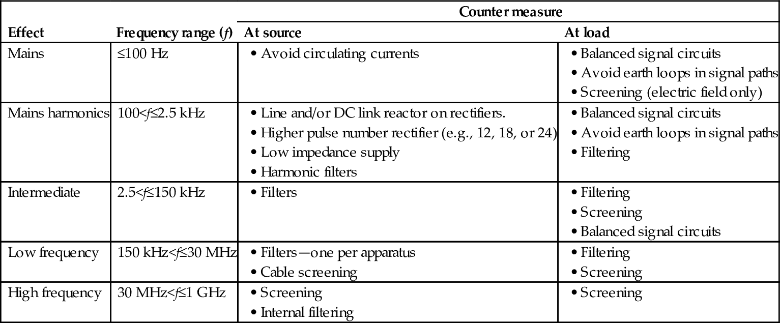
29.6.7 Techniques Used to Reduce the Effect of PMP Voltage Waveform
29.6.7.1 Output Line Reactor
A reactor increases the rise time, but the benefit of its connection may be negated as follows:
• Beneficial connection if cable length is short enough for reflections to be superimposed within rise time, that is, if rise time is increased beyond critical value of cable length.
• Harmful connection if cable length is too long; the reactor may have negligible effect on peak voltage (theoretically, its presence is insignificant in this case) or ringing period, but it will increase the duration of each overshoot, thus increasing the probability of partial discharge.
Adding a series line reactor between the motor and inverter is not as simple as illustrated above because the reactor adds or adjusts other resonant modes where the reactor rings with lumped capacitance. These resonant modes are pure transmission line modes and can double voltage. Some line inductance helps short-circuit protection. If earth current is limited by other means, then the coupled reactors may be helpful.
29.6.7.2 Sine-Wave Filter
This mechanism filters the PWM carrier frequency; thus, the converter output voltages are sinusoidal. This type of filter is best suited for low-performance drives and/or retrofit applications (old or standard motors). Ref. [13] and Table 29.17 illustrate the filtering options for high-power VSDs.
Table 29.17
Filtering options for PWM-VSI drives (Ref. [13])
| Option | No filter | dV/dt filter | Sine-wave filter |
| Motor dV/dt | High | Acceptable | Low |
| Motor insulation | Must be increased | Normal | Normal |
| EMC ground noise | Very high | Low | Very low |
| PWM carrier at motor | 100% | 100% | Very low |
| Motor audible noise | Higher | Decreased a little | Minimum |
| Motor derating | Approx. 13% | Approx. 3% | 0% |
| Torque response | Fast | Fast | Suits most applications |
| Motor cost | Typically +10% cost | Normally no extra cost | No extra cost |
| Conclusions | Impractical | Suitable only for high dynamic torque response | Best choice for most drives |
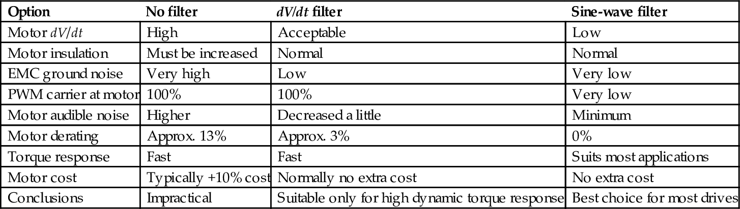
Employing a filter at the inverter output has some practical consequences:
• Filter power losses and voltage drop
• A small derating of power switches due to circulating current between filter L, C, and DC link capacitor
• Reduced torque response due to time delay in the filter, sine-wave type
• Potential oscillations that have to be electronically dampened
• Potential induction motor self-excitation
29.6.7.3 PWM (dV/dt) Filter
This reduces the dV/dt seen by the motor to a level, which does not compromise the motor or EMC. It is ideal for high-performance drives with custom-built motors.
29.6.7.4 RC Filter at Motor Terminals
A simple RC network is used at the motor terminal; the capacitor would represent a short circuit for the high-frequency components (sharp dV/dt). Wave reflection will not happen if the resistor value is similar to the cable characteristic impedance. Resistor losses are generally small, as current flow will only occur at the rising and falling edges of the PWM waveform.
29.6.7.5 Common Mode Reactor
The presence of capacitive current due to the high dV/dt can be improved by employing a common-mode reactor. It is well established that such a choke is not effective to reduce the RMS and mean values of the leakage current but only effective to reduce the peak value. The presence of such a choke in the circuit increases the inductance and resistance of the zero sequence impedance.
29.6.8 Supply Front-End for PWM-VSI Drives
There are many types of PWM voltage-source drive depending on the supply front-end type and regenerative technique employed (Table 29.18):
Table 29.18
Types of supply front-end bridges of PWM-VSI drives
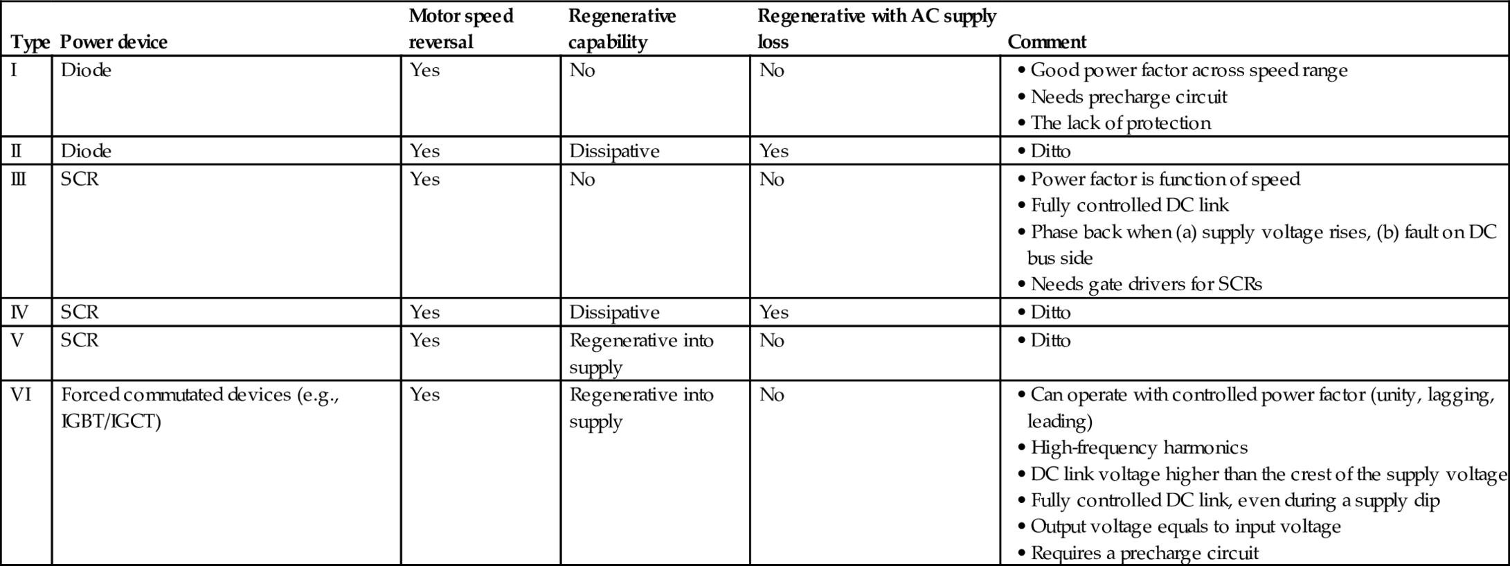
(i) PWM-VSI with a diode supply front end
(ii) As above but with a dynamic brake chopper
(iii) Fully controlled thyristor front end
(iv) As above but with a dynamic brake chopper
(v) Fully controlled antiparallel thyristor supply bridge
(vi) PWM supply front end
The use of a higher pulse number than 6-pulse would necessitate the use of a supply transformer. This is always considered to be an unnecessary “evil” because of additional cost, losses, and the need for extra space to accommodate this component. For MV applications, this is considered to be a necessity for isolation and protection.
29.6.8.1 Regenerative Braking
Several techniques are usually used for regenerative braking.
A simple diode front-end supply bridge will operate in two quadrants (positive and negative speeds). There is no regenerative power capability as any regeneration of power would result in an increase in the DC link voltage, and the drive will trip on overvoltage.
If a small amount of regeneration is required, during stopping, or speed reversal, then a dynamic brake chopper may be used. This is a simple chopper with a dynamic brake resistor. The size of the resistor is very much dependent on the regenerative brake energy, its magnitude, and repetition rate.
Full power regeneration is possible by employing a fully controlled antiparallel thyristor front end. This is similar to that used on DC drives or cycloconverters.
A more modern approach is to use pulse converter front end (fully controlled bridge). This is a four-quadrant converter with the ability to control the power factor and the DC link. Such an option necessitates the use of a precharge circuit for the DC link and smoothing inductance on the AC side.
For fully regenerative drives, the supply needs to be receptive.
By using a PWM rectifier as a primary converter in this composite structure, both the problems of regeneration and line current distortion are successfully solved—with the penalty of having a much more complicated converter structure and control system.
With the modern PWM-VSI VSD controller, the supply bridge can be fully controlled. Such an option offers the following benefits:
• Unity power factor all time
• Sine-wave input voltage and current
• Can operate with controlled power factor (e.g., leading power factor)
• Can operate as an active filter while supplying power to the load. Possible elimination of low-order supply harmonics (fifth and seventh)
• Output voltage equals the input voltage
29.7 Applications
29.7.1 VSD Applications
Table 29.19 summarizes main industries and applications.
Table 29.19
Application analysis of VSDs
| Industry | Current drive topology | Preferences | Applications |
| Power generation | Direct on line (DOL) | Boiler feed pump, start-up converter, coal mills | |
| Soft start | |||
| CSI3 | |||
| Petrochemical | LCI | Petrochemical and derivatives, gas liquefaction, pipelines and storage, oil on/offshore and pipelines | |
| DOL | |||
| CSI3 | |||
| Mining | Cycloconverters | Mine winders, conveyor belts, coal mills, ventilation fans, underground machinery | |
| Stand-alone and process industries | Water and sewage pumps, wind mills, material handling (extruders), test benches, paper and plastic machines | ||
| Metals | Mill drives—cycloconverters | Hot mills, medium section mills, finishing section mills, cold mills | |
| Marine | LCI cycloconverters | Warships, drilling vessels (mono hulls), chemical tankers, shuttle tankers, cruise liners, icebreakers, semisubmersibles, fishing vessels, cable layers, floating exploration rigs, ferries, research vessels, container vessels | |

Present solution of drives and electric drive application examples from various industries have been described in this section.
29.7.2 Applications by Industry
29.7.2.1 Deep Mining
Ref. [14] lists various high-power MV VSI inverter drive applications for the mining industry. In deep mine conveyor belt applications, a PWM-VSI drive offers significant advantages over other conventional alternatives. The following benefits have been identified for deep mine conveyor belts applications:
• Improved drive starting and stopping
• Improved reliability
• Matching belt speed to production
• Easier belt inspection
• Reduced belt wear and increased belt life
• Lower specification belt material may be used
• Low speed running to reduce coal removal by windage
• Manpower saving—less coal spillage
• Unity power factor with low harmonic content
• Reduced AC supplies disturbances
For hoist applications, the PWM-VSI drives can also be used to replace DC and cycloconverter drives for mine hoist applications. The benefits are the following:
• Improved drive control, with 100% continuous stall torque available with induction motors
• Reduced AC supplies disturbances
• Very unlikely to need reactive MVAR correction even at high ratings
• Improved immunity to AC supplies dips
The use of electrically coupled mine hoist systems has many advantages especially for deep mines and set to become an essential feature of many new mine shaft systems. The circuit is shown in Fig. 29.8.
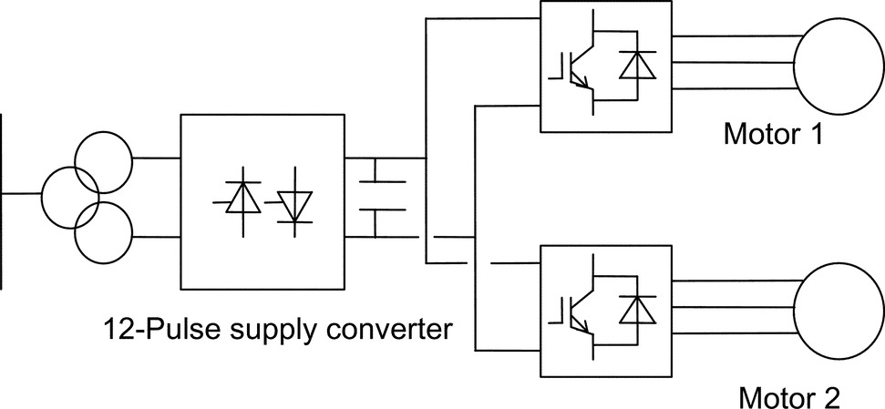
The power flows naturally from motor 1 to motor 2 such that at the point of balance, the AC supply current is virtually zero and at near-unity power factor.
This technology is the natural successor to the DC electrically coupled winders and totally solves the poor AC power factor that would result if twin drive cyclo motors were used.
29.7.2.2 Industrial Processes
In this industry, there are a number of viable drive solutions available for the major market power ranges, from LCIs to FCI. However, there is a developing market for MV variable speed drives. The PWM-VSI using new high-power IGBTs or IGCTs appears to be the best solution for the future. Benefits include better power factor, no limit on frequency, and higher voltages.
PWM-VSI converter cost is likely to be higher than equivalent other well-established technologies (e.g., LCI). Hence, the flexibility in choice of motors and improved control must be exploited. The advantage of offering an MV solution may prove significant. Possible means of reducing motor costs are the following:
1. Higher frequencies are achievable, allowing the use of high-speed motors and gearboxes.
2. Higher pole number machines can be used, giving a cost saving.
3. Better power factor over the speed range giving power supply saving.
4. Induction motors with rotors adapted for use with VSDs can be used with resultant cost savings over standard DOL, fixed speed motors.
5. Higher voltages and smaller conductors.
6. However, at low powers, the relative cost of the machines is less significant versus the cost of the converters. Hence, the viability of this technology in this market requires close examination.
The cycloconverter drive with a synchronous motor is used when four-quadrant operation is required. Particularly for high power rating with high torque at low speed and at standstill but with a rather low maximum speed are drive requirements. Gearless cement mill drives were the first applications of cycloconverters. The mill tube is driven from low-speed wraparound motor with a high number of poles.
29.7.2.3 Metal Industry
The majority of installed hot mill drives are cycloconverters. A few LCI drives have been used, but applications are limited for such technology on mill main drives. Most early-generation plants are equipped with DC drives. The trend is to replace DC with AC.
Direct current drive applications were universally used in the first generation of rolling mills. The market for new mills requiring this technology is declining as the steel industry moves to AC as a preference. On early-generation mills where motors are retained, DC drives are likely to be required. Customers in their inquiries, some requesting AC alternatives, are still requesting DC drive solutions.
DC drives are probably still the most economic for the power range of 750–1500 kW. The number of manufacturers however, producing DC motors, is declining, particularly in the case of large DC motor manufacture. The lower price of DC solutions is offset by the advantage of the use of AC motors in AC solutions, making AC the more popular choice.
Current-source inverter LCI can be applied to roughing stands of rod and bar mills. Technical limitations include the risk of torque pulsation and a minimum drive output frequency of 8 Hz.
Cycloconverter is the solution most often used. However, it is relatively expensive compared with alternative technology. Major cost penalties arise from supply transformers, cabling, and bridge configuration. In some cases, active power supply compensation equipment may be required, taking the costs even higher. Cycloconverter solutions will still be cost-effective for medium-to-high power, low-speed, low-frequency (say below 21 Hz maximum operating frequency) applications. This would include hot reversing mills, with direct drive, for the primary rolling processes, albeit a declining application area, and possibly for direct-drive, low-speed, high-torque roller-table applications. Technical limitations include limited output frequency (typically 29 Hz for 12-pulse at 60 Hz supplies), which can necessitate the use of two-pole motors to reach application speeds.
The high-power PWM-VSI using new power devices (IGBT/IGCT) appears to be the best solution for the future. Benefits include better power factor, no limit on frequency, and higher voltages. Potentially, either the two-level or the multilevel solution will meet the market requirements.
In some applications, like coilers/uncoilers, the system is composed of several drives, which have different power cycles; when some drives are furnishing power, others are braking. A common DC bus system will allow that the energy fed from drives operating in the regenerative braking mode will be utilized by other drives connected to the same DC bus but operating in the motoring mode. The supply bridge, that is, rectifier, feeding the DC bus system will only be rated for the total system power.
The benefits of the DC bus systems include the following:
• Low harmonics (lowest when using 12-pulse or 18-pulse front ends)
• Possibility of energy transfer on the common DC link solutions (reducing front-end converter and transformer sizes with attendant energy saving, possibility of using kinetic energy to allow controlled stopping)
29.7.2.4 Marine and Offshore
Drive powers are commonly in the range of 0.75–5.8 W for thrusters and 6–24 MW for propulsion. The evolution in the commercial market is toward powers from 1 to 10 MW for propulsion. Higher powers are required for naval applications with package drive efficiency better than 96%.
The PWM inverters at these powers would allow the use of induction machines, rather than the more expensive synchronous alternatives required for LCI drive. This could give savings in the price of the motor.
Current source inverter (CSI) drive LCI is used for all applications except for icebreakers where cycloconverter drives are used. The PWM (voltage source) inverter using new force-commutated drive appears to be the best solution for the future. Benefits include better power factor, no limit on frequency, and higher voltages. Many icebreakers and some other ships are equipped with diesel-generator-fed cycloconverter synchronous motors with power ratings up to about 20 MW per unit.
29.7.3 Examples of Modern VSD Systems
29.7.3.1 Integrated Power System for All Electric Ship
This is a full-scale main propulsion drive for the US Navy [15]. It consists of a main propulsion 19 MW induction motor drive system. The power converter consists of three 6-pulse rectifier stages, three 6 kV DC links, and 15 IGBT-based H-bridges feeding a 15-phase induction motor (Fig. 29.9).

This drive demonstrates the potential of modern power electronics over more traditional solutions such as cycloconverter and LCI. The volumetric power density of the new converter is reported to be 905 kW/m3, compared with 455 kW/m3 for cyclo and 313 kW/m3 for LCI.
29.7.3.2 Subsea Separation and Injection System
This is a full-scale pilot plant developed to increase recovery and improve the economics of offshore oil and gas fields. The system comprises several VSD units, typically 500 kW oil pump, 1 MW multiphase booster and 1–2.5 MW water injection drive unit, and such a system is called “SUBSIS” [16]. The main task for such a system is to separate the bulk water from the well stream and treat it either for discharge into the sea or reinjection into the reservoir.
This system employs subsea-based rotating machinery for pumping, boosting, and compression. The subsea electric power distribution system (SEPDIS) is an innovative and cost-effective subsea processing (Fig. 29.10). The pump motors are mounted in a pressurized vessel and positioned on the seabed. Ref. [16] identifies the benefits of subsea drives as follows:
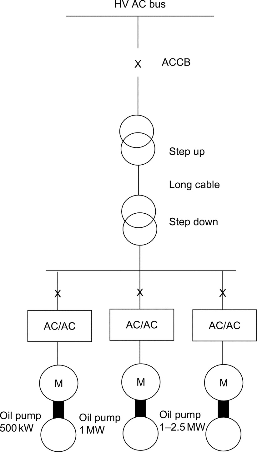
• 3%–6% increase in oil and gas recovery
• Improved pipeline transportation conditions by removing water from the well stream
• Reduced environmental impact due to lower energy consumption and reduction in chemicals used to inhibit corrosion
• Reduced size and cost of new platforms
• Cost-effective development of marginal fuels through reuse of existing infrastructure
29.7.3.3 Shaft-Generator for Marine Application
During cruising at sea, up to 3.5 MW of electric power is extracted from the ship's main diesel engine/propeller shaft (90,000 hp per ship) via a salient pole shaft generator, which is fitted to the main propeller shaft. The converter output voltage (set at 60 Hz) is stepped up to 6.6 kV [17].
The converter is based on 24-pulse converter (LCI) technology, which is traditionally used as main ship propulsion. The shaft generator output frequency varied between 14 and 25.7 Hz; six-phase generator and the output stage are configured as 24-pulse, via a step-up transformer. At the output, a passive LC filter is employed, with a synchronous condenser started by a pony motor.
This type of application is likely to significantly benefit from the higher volumetric power density of the PWM-VSI with fully controlled front-end. Such a system will eliminate the need for a passive filter at the output stage and use a standard three-phase generator.
The same technology is also applicable to high-speed generators and windmill energy. The ability of the active front end to sustain fixed DC link voltage over a relatively wide shaft speed range results in a very good control of the output voltage, irrespective of the shaft speed.
In wind power plants, the optimal efficiency of the wind turbine depends on the speed when the wind conditions change. It is, therefore, advantageous to vary the speed of the generator and link it via a frequency converter to the AC system.
For high-speed generators, driven by diesel engine or gas turbine, the fully controlled converters enable direct power conversion from AC high frequency (hundreds of Hz) to fixed power frequency (50/60) Hz fixed output voltage. The magnitude of the output voltage is kept constant irrespective of speed variation of the generator (Fig. 29.11).
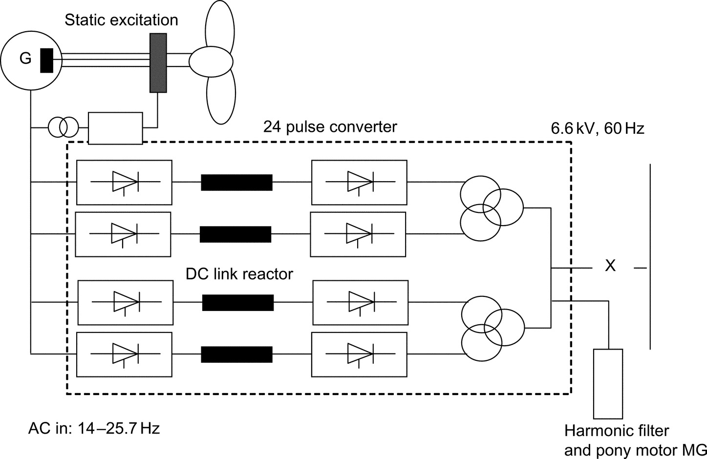
29.7.3.4 Linear Motor Drive for Roller Coaster
This drive involves a fully regenerative PWM-VSI. The supply front end is made of antiparallel thyristor front end, while the machine bridge is based on PWM IGBT VSI. “Superman” has been developed for Six Flags California at Magic Mountain. The inverter output frequency is 0–230 Hz and 525 V AC RMS. The power rating is 1.8 MW. The duty cycle is 1.8 MW for 7 s, followed by 16 s at zero power, and 1.3 MW for 5 s and a stop period of 32 s. This ride involves acceleration at 4.5 g, speed and free fall (6.5 s of weightlessness, during which a height of 415 ft is achieved [18]).
The same concept employed in this application could be used for aeroplane launcher on aircraft carriers, instead of the conventional catapult.
29.8 Summary
The benefits of VSD are there to be quantified, and energy saving has been the prime reason for employing a VSD in stand-alone drive applications. Other benefits such as improved process control or increase life expectancy are often difficult to quantify in real terms.
There is a large selection of VSD systems to meet a wide range of applications. In the low and medium power, the induction motor and PWM-VSI are supreme. At higher power ratings, MV PWM-VSIs are gaining popularity, but LCI and cycloconverter drives would remain key technologies with very high power applications.
Modern drives are becoming more available at competitive prices with good reliability record. However, there are concerns with regard to the impact of fast switching on the motor and the environment.
To ensure successful implementation of a VSD system, both the supplier and end users need to work in partnership. Ideally, one competent supplier should supply the full drive package, with some after-sale service support. Understanding the nature of the load plays an important role in specifying the power rating of VSD correctly to meet performance requirements and required life expectancy.
New areas of VSD applications are emerging as the power electronics advances and become more reliable at affordable prices. Packaged drives up to several hundred kWs are becoming a commodity product, and end users do not need to involve a third party during specification, installation, and commissioning. Integrated motors are likely to increase their popularity, possibly with new types of power converters, for example, matrix.