
Wireless Charging of Electric Vehicles
Chun T. Rim GIST, Gwangju, South Korea
Abstract
Wireless power transfer (WPT) is one of the hottest topics being actively studied, and it is being widely commercialized. In particular, there has been a rapid expansion of WPT in mobile phone chargers, stationary charging electric vehicles (EVs), and dynamic charging EVs, also called road-powered EVs (RPEVs). It is expected that WPT industry will grow persistently in the coming decades.
In this chapter, the concepts and practical applications of WPT to EVs are introduced. Inductive power transfer (IPT) for stationary and dynamic charging EVs is explained in detail. Design examples with experimental verifications are provided to help beginners of IPT to develop their own IPT products for EVs.
Keywords
Wireless power transfer; Inductive power transfer; Capacitive power transfer; Road-powered electric vehicles; Stationary charging; Dynamic charging; Online electric vehicles; Gyrator; Magnetic mirror; EMF cancel; Segmentation of power rail
34.1 Introduction to Wireless Electric Vehicles
In this section, a new concept of “wireless electric vehicles (WEVs),” which is coined by the author, is introduced, and wireless power transfer (WPT) technologies including inductive power transfer (IPT) and capacitive power transfer (CPT) are explained. Then, introduction to electric vehicles (EVs) is briefly provided.
34.1.1 The Needs for Wireless Electric Vehicles
Why most people are still not daily driving an electric vehicle?
As a customer, I feel that EVs are still very expensive and inconvenient compared with existing conventional internal combustion engine (ICE) vehicles. The structure of an EV is relatively simple and easy to have maintenance; however, it is not cheap and heavy because of its onboard batteries. Still, most EVs have much shorter driving distance for a full charge compared with ICE vehicles.
Therefore, it can be said that EVs have not been widely commercialized because of battery and charging problems, as shown in Fig. 34.1.
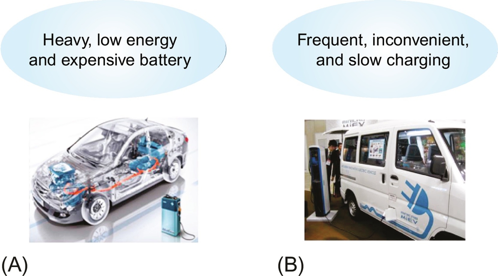
Remark that battery EV (BEV) had been commercialized since the late 19th century, which is about 20 years earlier than the commercialization of ICE vehicles. The original BEVs disappeared from markets because the battery was too heavy, required long time to recharge, had a relatively short driving distance, and was expensive. Amazingly, these problems of battery still exist compared with current ICE vehicles nevertheless the drastic improvement of EV batteries. The expensive price of EVs is mainly due to battery price. The improvement of battery is very slow and does not follow the Moore's law because it is not governed by electronics but governed by chemistry.
Another major obstacle for commercialization of EVs is the charging problem. Even though innovative batteries will become available, still we have charging problems. We should have 30 C (1 C corresponds to the rated power or energy capacity of a battery for an hour) charging capacity in order to recharge an EV in 2 min in case we have such a good battery. For a 50 kWh battery example, which is common to a long-distance EV now, we should have at least 1.5 MW power rating charger and power distribution facility to support it. In practice, we should recharge an EV frequently in order to avoid the battery empty. If a cable charger is used, it is very inconvenient to plug in and plug out daily, and it is potentially dangerous to deal with the connector of a cable manually under wet conditions. Currently, a quick charger can recharge an EV battery up to 80% within 20 min, which is still too long time for customers accustomed to 2 min refueling.
Two possible solutions to the abovementioned problems are summarized in Fig. 34.2.

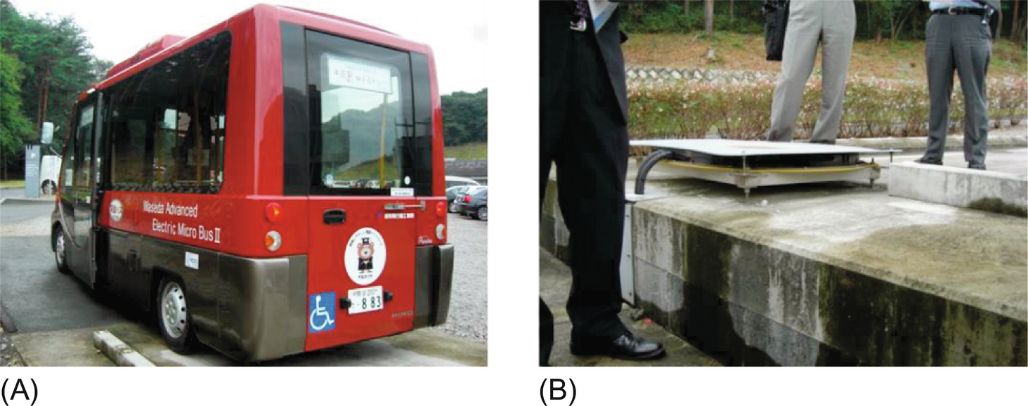
The first solution is to adopt the road-powered EV (RPEV) [1,2] or online electric vehicle (OLEV) [3–19], which does not rely on the battery but gets power directly from roadway power supply rails. This charging method is often referred “the dynamic wireless charging” or simply “dynamic charging” because power is delivered to an EV when it is in motion. An RPEV has a battery for temporary energy storage, but its size is a few times smaller than a BEV, which is not an obstacle for commercialization. As shown in Fig. 34.2A, RPEVs have replaced conventional conductive EVs that have wearable pantographs and cumbersome power lines.
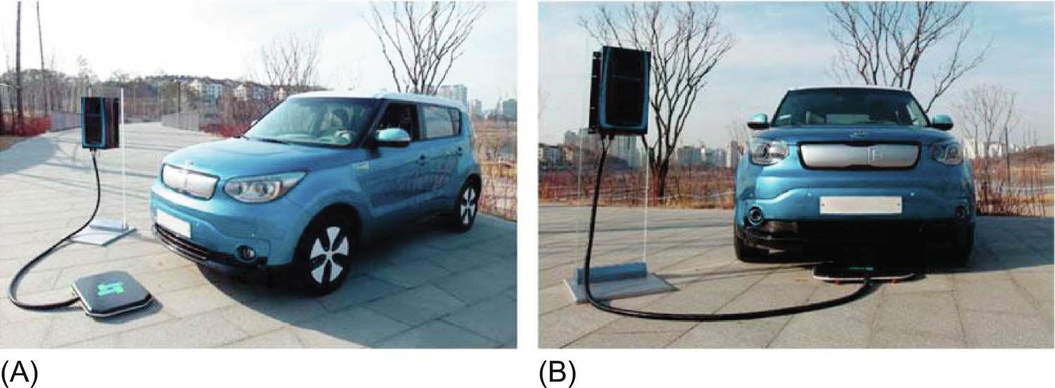
The second solution is stationary wireless charging [20–25], often called as “static charging,” by which the inconvenient and dangerous cable charging problems can be completely solved, as shown in Fig. 34.2B. The stationary wireless charging can be applicable to both plug-in EVs (PHEVs) and BEVs. Of course, the slow charging problem cannot be directly solved by the wireless charging, and it must be mitigated by other means such as “interoperable road-powered supply rails [26],” on which this stationary wireless charging is also made together with RPEVs.
I would like to call the stationary and dynamic charging EV solutions as wireless EVs (WEVs), which embrace WPT and wireless communications for EVs. As EVs evolve to information platforms in the future, wireless communications will be essential to every EV, which results in ubiquitously connected cars. WPT will make the WEV complete.
34.1.2 What is Wireless Power Transfer?
In general, the methods of power transfer (PT) can be classified to the stationary PT and mobile PT depending on the movement of loads, as shown in Fig. 34.3. WPT is nowadays the most preferable way of mobile PT that embraces inductive PT (IPT), capacitive PT (CPT), radio-frequency PT (RFPT), and optical PT (OPT), whereas the wired PT can also provide power over a flexibly long distance if properly designed. Currently, IPT is the most widely used one among WPTs, which will play a significant role in realization of the Internet of things (IoT), comprising of digital communication devices, sensors, software, and power sources.

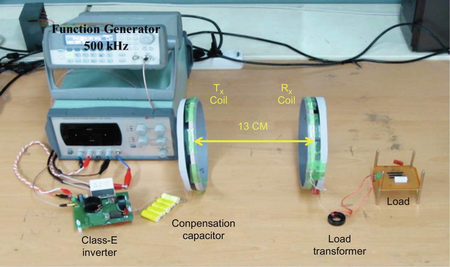
An experiment kit, for example, WPT, is shown in Fig. 34.4, where two air coils are used to transfer power “wirelessly” through “magnetic coupling” or “inductive coupling” of the coils and compensation capacitors are used to nullify the reactance of LC resonant circuits. An inverter is used to provide high-frequency AC current to a transmitter (Tx) coil, and a load transformer is used to adapt the induced voltage of a received (Rx) coil to a load voltage level.
What do you think about the characteristics that a WPT system should have?
First, the delivered power level for a load should be enough, and its power efficiency should be also high enough not to generate excessive heat and waste electric energy.
Second, the cost, mass, and volume of a WPT system are quite often problems compared with existing wired solutions.
Third, system resilience against resonance parameter changes, load changes, input voltage changes, proximity object movement, electromagnetic interference (EMI), and environment changes such as temperature, humidity, vibration is found to be very important in a WPT system.
Fourth, system dynamics such as response time, stability, and dynamic operating range should be met.
Fifth, accommodation, deployment, and user interfaces of a WPT system should be well considered from design phase for a successful development.
The abovementioned aspects of a WPT system are not necessarily in the order of importance, and they are strongly correlated with each other. Like other systems, the WPT system is a complex system of mechanical and electric compartments, and the design of a WPT system requires comprehensive trade-offs among the requirements. It can be said that the development of a WPT system is not a systematic science but an art of system engineering.
34.1.3 Introduction to Inductive Power Transfer
In general, it can be said that the IPT is governed by Ampere's law and Faraday's law among four Maxwell equations, as shown in Fig. 34.5. The governing equations of IPT in the steady state for a sinusoidal magnetic field, electric field, and current density at low frequency are approximated by letting D=0 as follows:

The principle of IPT power delivery can be sequentially explained as follows:
(1) Time-varying magnetic flux is generated from the Tx coil according to Ampere's law.
(2) Induced voltage is generated at the Rx coil according to Faraday's law, where magnetic flux comes from the Tx coil.
(3) Induced voltage, called back emf (counter electromotive force), is also generated at the Tx coil by the Rx coil current.
(4) Power is provided to the Tx coil and fetched from the Rx coil; thus, wireless power is delivered through the coils.
As identified from the above four steps, the IPT is essentially a transformer. A major difference from an ideal transformer, however, is relatively large leakage inductances at both the primary and secondary sides because of weakly coupled inductors. This is why we need the capacitors, as shown in Fig. 34.5B, which are mostly used to compensate the reactance of corresponding leakage inductances. Depending on the source and load types, the compensating capacitors can be connected in series or parallel; Fig. 34.5B shows a series-series (S-S) compensation example.
For the circuit level analysis of IPT, an equivalent circuit for the coupled inductors in the dotted box of Fig. 34.5B is highly needed. There are three equivalent circuit models widely used for the coupled inductors in IPT, as shown in Fig. 34.6. As shown in Fig. 34.6A, the transformer model is convenient for designing parameters when explicit circuit variables are sought for. The mutual coupling model (M model) of Fig. 34.6B is conveniently used when each side is regarded as an inductor and a back emf voltage source, which represents mutual inductive coupling. Though the trivial galvanic isolation is not countered, the most simplified IPT model would be the “T”-shape model (T model), as shown in Fig. 34.6C, which comprises three inductors only and does not apparently show any turn ratio. Note that the three models are valid not only in the steady state but also in the transient state [27].
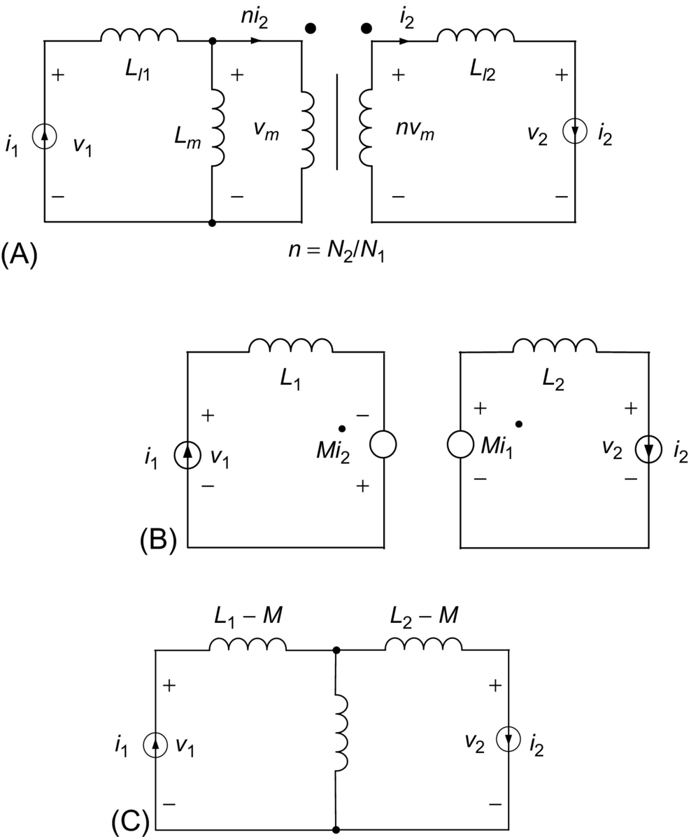
The governing equations for the transformer model and M model can be related as follows:
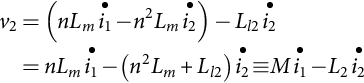
Note that the upper dot of a variable is the time derivative of the variable, and the equations are valid for in general.
The T model can be derived from the M model of (34.2) by rearranging terms as follows:
34.1.4 Introduction to Capacitive Power Transfer
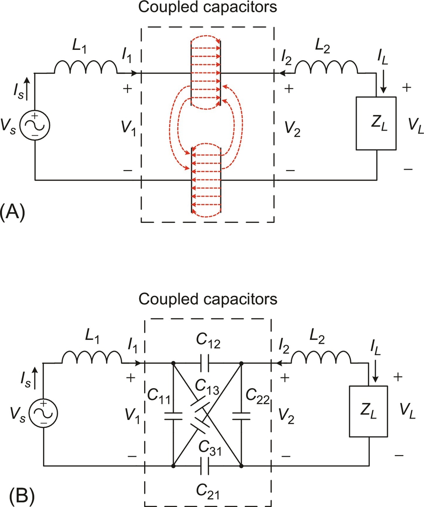
CPT has not been widely used in WPT compared with IPT due to its low power delivery capacity and high operating frequency. However, CPT has advantages for compact and thin layer applications with low power. The configuration of a CPT system is shown in Fig. 34.7, where other modules are very similar with IPT except for Tx and Rx plates and electric-field-based communication links. The application of CPT to EV is available in a few literatures [25].
34.1.5 Introduction to Electric Vehicles
Generally speaking, an EV comprises a conventional car body, and EV-specific components such as energy refuel equipment (electric chargers), onboard energy storage (batteries), power converters (inverters and rectifiers), and locomotive (electric motors and transmissions), as shown in Fig. 34.8.
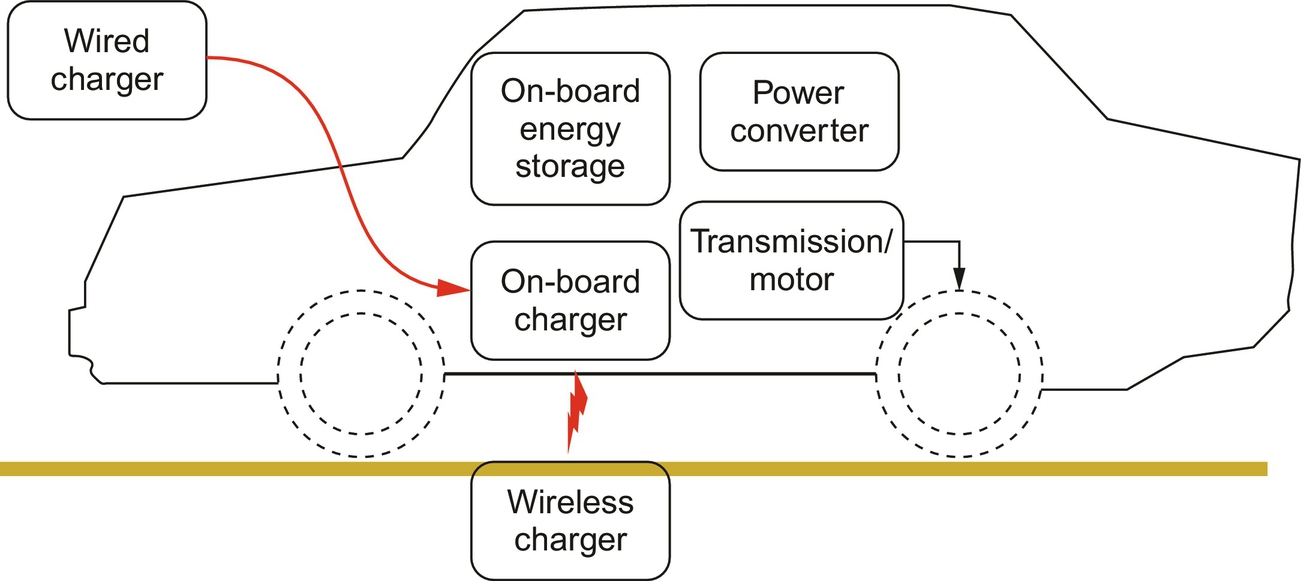
It is instructive to find the analogy between EVs and ICE vehicles: electric charger versus fueling station, battery versus fuel tank, inverter versus fuel injector, and electric motor versus ICE [28].
Depending on the energy source/refueling method, EV-specific components mentioned above, and various applications, EVs can be classified into many categories. EVs can be classified, according to energy source or energy refueling method, as wired power EVs, wireless-powered EVs (WEVs), solar- or RF-powered EVs, and battery-swap EVs. Depending on the onboard energy sources, EVs can be classified as ICE-powered EVs, called hybrid EVs (HEVs) or plug-in hybrid EVs (PHEVs), fuel-cell-powered EVs (FCEVs), and even nuclear-powered EVs though not likely to be commercialized in the near future. EVs can be also classified into applications such as ground (road and rail), aerial, sea (ship/underwater), and space EVs.
34.2 Static Inductive Charging of Battery Electric Vehicles
In this section, it is explained how IPT is applied to the static chargers for EVs such as BEVs and PHEVs.
34.2.1 Overview of Static EV Chargers
Because automatic refueling of a vehicle is a wonderful thing for the person, boring of repeated daily cable charging of EVs, static EV chargers of this category are expected to be widely used in the near future. As identified from recently developed autonomous vehicles and self-controlled vehicles, future vehicles will be not only transportation tools but also information platforms. EVs are inherently the most electrified vehicles, which make the information platform be possible.
Among numerous static EV chargers, a few implemented examples are shown in Figs. 34.9 and 34.10.
A static EV charger can be decomposed into a Tx subsystem on ground and an onboard Rx subsystem. The system requirements of a static EV charger include cost, reliability, lifetime, availability, power, efficiency, tolerances (height, longitudinal, and lateral), electromagnetic field (EMF), foreign object detection (FOD), and robustness against mechanical shock for a given source and load conditions, air gap, load change, and operating temperature. Hardware and software implementation issues such as insulation, waterproof, user interface, monitor, communications, and information are also important for the development of the system. Standardization and regulation issues are crucial for commercialization.
34.2.2 Coil Design Issues
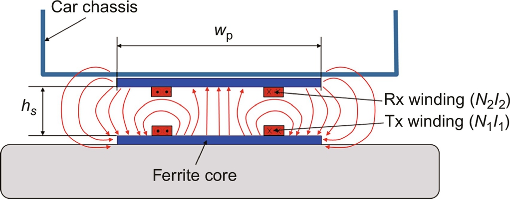
Coil design would be the most substantial part of IPT system design because the Tx coil and Rx coil determine power transfer performances such as output voltage, power level, coil-to-coil efficiency, and height/lateral tolerances. The configuration of a static charger includes Tx and Rx windings and cores, as shown in Fig. 34.11. The goal of coil design is to focus magnetic field from the Tx to Rx coils so that leakage flux is minimized to lower EMF. In detail, to design the coil is to determine the ampere-turns (N1, N2, I1, and I2) and detail dimensions of coils for a given air gap, width of coil, operating frequency, power supply voltage, delivered output power, and ambient operating temperature (hs, wp, fs, Vs, Po, and T).
There are a few decision issues in the design of Tx and Rx coils of static EV chargers. One of them is the coil shape, as shown in Fig. 34.12. The merits of the two types are listed below. The thick arrows depict lateral tolerances of two directions: the larger the arrow length, the bigger the tolerance. “S” and “N” denote magnetic polarity. There could be other shapes such as round shape, which is basically rectangular but its corners are round, and octagonal shape. Basically, the shape of the coil is largely governed by the shape of the mother body, that is, a car underbody, depending on applications.

As shown in Fig. 34.13, the lateral tolerance of a dual-pole coil could be better than that of a single-pole coil because the number of magnetic pole is only two for the dual-pole coil. The demerits are written in italic letters in Fig. 34.13.

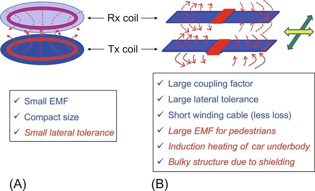
You should also determine the coil type depending on magnetic field shape you want, as shown in Fig. 34.14, where loop coil and dipole coil examples are selected. For a given size of the Tx and Rx coil, the dipole coil has larger lateral tolerance in side direction but has large EMF that needs more magnetic shield.
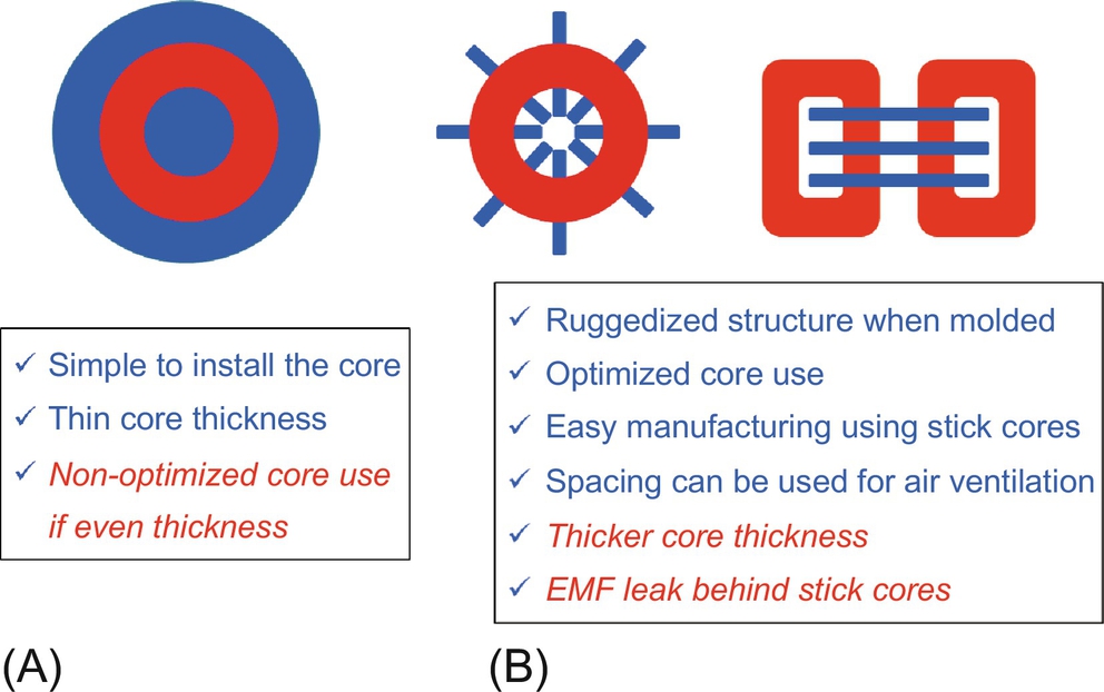
The core could be dense or sparse structures, as shown in Fig. 34.15. Note that the total amount of core use could be unchanged by the average density of core if the core thickness of dense core structure is optimized. If not the case, the core use of sparse structure tends to be smaller than the dense structure.
Another category of core structure is the use of core, as shown in Fig. 34.16. Core is not necessarily always used, especially when the operating frequency is too high to use any core, as shown in Fig. 34.16B. Note that the coreless coil is quite often referred as the coupled magnetic resonance system (CMRS), whereas the coil with core is called conventional inductive power transfer system (IPTS). The beginner who studies CMRS often thinks that it is quite different from IPTS due to its inherent large Q and no change of primary and secondary inductances against air-gap change. The wonderful characteristics of CMRS, however, do not come from its resonant type but come from its coreless structure, as the author announced at the Special Session of Wireless Power Transfer of the 2013 IEEE ECCE conference. As an evidence, 5 m-long-distance IPTS was built and first demonstrated that long-distance WPT is possible not only by CMRS but also by IPTS [29]. As denoted in Fig. 34.16, there are a lot of penalties for the coreless structure.

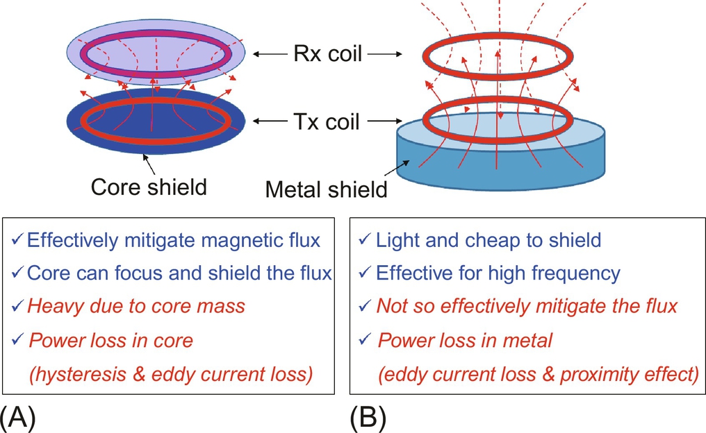
We have two shielding methods: core shield and metal shield, as shown in Fig. 34.17. Both shields are often used to enhance magnetic shielding effect. Note again that there are not many theories available for metal shield design compared with core shield design.
34.2.3 Misalignment Issues
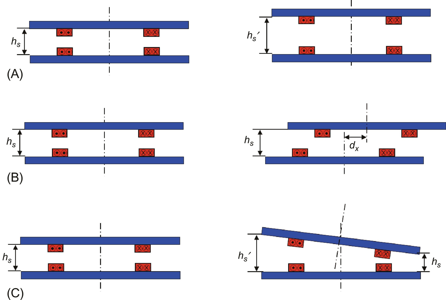
A very important and difficult problem in IPT design is position tolerance issue arising from air-gap change and misalignments between Tx and Rx coils, as shown in Fig. 34.18. As the coils are misaligned each other, induced voltage drops in general, and resonant frequencies of Tx and Rx sides usually change as well. Therefore, the position tolerance affects to not only coil design but also compensation circuit, controller, and converter designs such as power rating, zero voltage switching (ZVS) condition, and power factor.

34.3 Dynamic Inductive Charging of Road Powered Electric Vehicles
In this section, the WPT system (WPTS) for RPEVs is explained. Most recently commercialized OLEVs including narrow-width power rails of I-type and ultraslim power rails of S-type are explained, where the width of power rail is important in road construction of infrastructure for RPEVs.
34.3.1 Overall Configuration of RPEVs
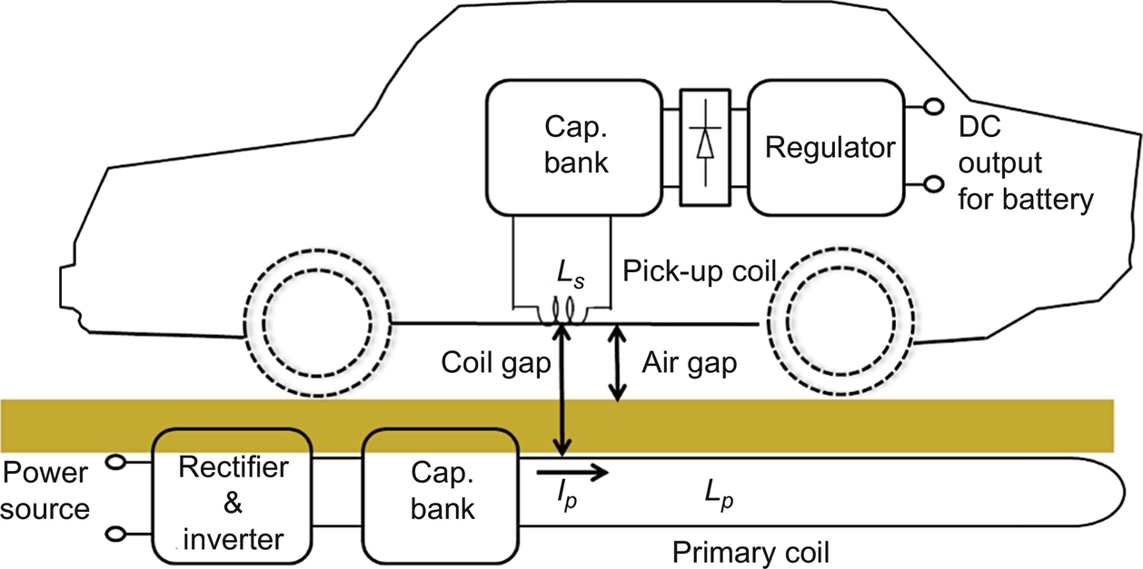
The WPTS for an RPEV should be capable of delivering high power efficiently through a moderate air gap for avoiding collisions between the RPEV and ground. The WPTS is composed of two subsystems: One is the roadway subsystem for providing power, which includes a rectifier, a high-frequency inverter, a primary capacitor bank, and a power supply rail, and another is the onboard subsystem for receiving power, which includes a pickup coil, a secondary capacitor bank, a rectifier, and a regulator for battery, as shown in Fig. 34.19. The roadway subsystem should be so robust and cheap that it may withstand severe road environments for a lifetime of an EV and should be economic to install over a long distance, whereas the onboard subsystem should be compact in size and light in weight so that it may be adopted into the RPEV.
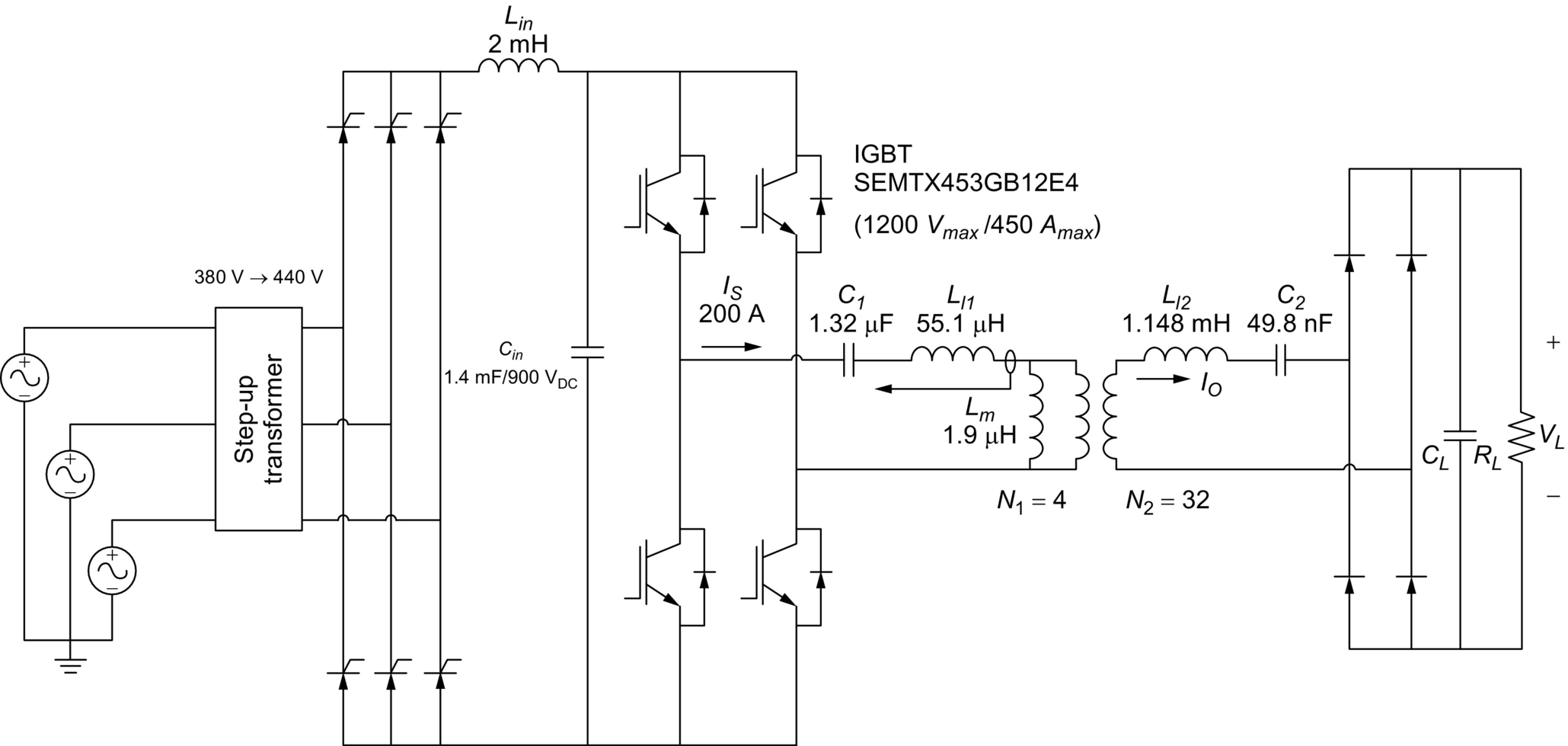
An example overall circuit diagram of an IPTS developed for OLEVs is shown in Fig. 34.20, where the inverter provides constant current to the Tx power rail by a feedback control.
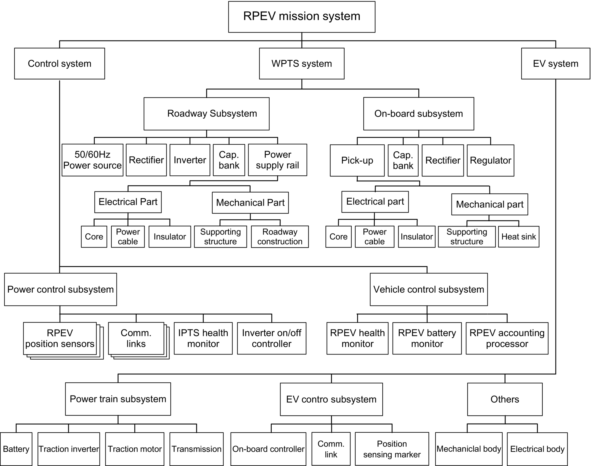
The overall system breakdown of an RPEV mission system is shown in Fig. 34.21, which is drawn, reflecting the experience of developing OLEV systems by the author. The RPEV mission system includes not only the WPTS system but also the control system and EV system. The control system is unique and crucial for RPEV because it senses and identifies the EV and then appropriately turns on and off the inverters. Moreover, it monitors the health of IPTS and RPEV and provides accounting service and communication links.
IPTS for RPEV is differentiated from conventional IPTS for stationary charging because additional requirements such as larger lateral tolerance, higher air gap, and lower construction cost should be considered for dynamic charging [3–19]. Moreover, IPTS for RPEV should survive from harsh road conditions such as extremely high and low temperatures, high humidity, and repetitive mechanical shocks for at least 10 years. Basically, the high-voltage power rail under a road should be electrically and mechanically protected well, but electricity under the conditions of a wet and fragile structure is not compatible with a road, in general. Therefore, it is quite challenging to build the roadway subsystem robustly. On the other hand, the onboard subsystem should also survive from the harsh road conditions and vibrating RPEV operating conditions, where strict technical and legislative regulations for vehicles should be met.
34.3.2 Design Issues of Dynamic Inductive Charging
The design goals of IPTS are summarized as follows:
(1) To increase magnetic coupling as much as possible so that higher induced voltage can be obtained.
(2) To increase power efficiency for a given power capacity, device ratings, and cost.
(3) To make modules as compact as possible to accommodate for a given space and weight.
(4) Not to increase or cancel out EMF.
(5) To manage resonance frequency variation and coupling factor change due to misalignment of pickup position, air-gap change, and even temperature change.
In order to meet the design goals, several important design issues of the IPTSs, which are unique for RPEVs, should be resolved as follows:
1. Switching frequency: The switching frequency of the inverter and rectifier of an RPEV governs overall performances. As the switching frequency fs increases, the coil and capacitor size decreases for the same required power, but the switching loss and core loss as well as the conduction loss of wires due to the skin effect increase. In the case of the switching frequency lower than 20 kHz, acoustic noise may be a problem [1]. Another unique feature of RPEVs concerning frequency is the increased voltage stress in a distributed power supply rail Vl1 for higher switching frequency, which is proportional to the frequency and line current Is as follows:

Because of these restrictions, the switching frequency tends to be no less than 20 kHz but not far beyond 50 kHz. For OLEVs, the frequency was finally selected as 20 kHz after examining for 20 kHz, 25 kHz, and 30 kHz.
The interoperability of IPTS between RPEVs and stationary wireless EVs is an important issue that needs further study because the design of IPTSs for RPEVs is not a direct extension of that of stationary chargers. The design goals of IPTS of RPEV such as low infra cost, high power, continuity of power delivery, and low fluctuation during in-motion are not so important for stationary chargers.
2. High power and large current: In addition to the high operating frequency of RPEVs, high power of hundreds of kW with large current of hundreds of A makes it difficult to handle cables, converters, and devices. For example, a Litz wire of 300 A rating with 20 kV insulation capability is not commercially produced. Capacitors and IGBTs, which have high voltage and large current ratings with an operating frequency higher than 100 kHz, become scarce. Furthermore, all the inverters, rectifiers, coils, capacitors, and cables used in the IPTS of RPEV are operated outdoors, where debris and salty and wet material may damage them.
3. Power efficiency: In order to make RPEV competitive against internal combustion engine vehicle (ICEV), the power efficiency or energy efficiency should not be too low. The bottom line of the overall power efficiency, which is defined from the AC power source to the DC output power for battery, would be about 50%, considering grid loss and fuel cost. Fortunately, modern IPTSs have fairly good power efficiency larger than 80%. More importantly, power loss rather than power efficiency is a serious problem in designing the inverter and pickup due to over temperature.
4. Coil design: In order to focus magnetic field for Tx and Rx coils and to mitigate magnetic leakage flux so that large induced voltage and low EMF level can be achieved, a novel coil design is crucial for IPTS. This design is unique for the roadway subsystem in that the cost per km is critical; therefore, the roadway power supply rail should be cheap enough not to deteriorate the economic feasibility of overall RPEV solution, whereas the pickup should be neither heavy nor thick so that it can be successfully implemented on the bottom of an RPEV.
5. Insulation: In order to guarantee stable operation of IPTS, a few kV level insulations of the roadway subsystem and onboard subsystem should be provided. The insulation of a roadway power supply is of great importance because high voltage is induced along through the distributed power rail over a road rather than over a point and is increased by the back emf of the pickup coil abruptly displaced on the power supply rail. The insulation of the pickup coil is also an important issue when high power output is sought because the large output current of the pickup coil induces high voltage, which could be as much as 10 kV if not appropriately mitigated.
6. Segmentation of power supply rail: RPEV typically requires many IPTS along a road because a power supply rail cannot be infinitely deployed. It should be segmented so that each segment can be independently turned on and off. The length of a power supply rail is an important design issue because it would be too expensive if the length is very short due to an increased number of inverters and switch boxes, whereas the power loss would be too large if the length is very long due to increased resistance. Besides these issues, the amount of cable use, EMF level, and car length should be considered when determining the segmentation scheme.
7. Roadway construction: In order to minimize traffic obstruction, the roadway construction time of IPTS should be as short as possible. Moreover, there are numerous difficulties in roadway work because of debris and dirt. Keeping all of the electric components of IPTS clean during roadway construction for a few days or weeks is a serious problem in practice. There should be a smart way to overcome these problems.
8. Resonant frequency variation: The resonant frequencies of the roadway subsystem and onboard subsystem are significantly varied as the magnetic coupling between a power supply rail and a pickup changes due to air-gap change, lateral misalignment, and longitudinal movement. Moreover, the frequency changes are different from time to time for different cars and different numbers of cars on a power supply rail. There should be either the smart coil design or inverter design to cope with these frequency changes or in situ frequency tuning capability.
9. Control of dynamic resonating circuits: The resonant circuit, as shown in Fig. 34.20, has finite dynamic response times and may arise high voltage and current peaks that can destroy electric devices. They should be moderately controlled so that the voltage and current level can be mitigated, where the frequency response of AC circuits can be managed with the recently developed Laplace phasor transformation [30,31]. A resonating LC circuit has a first-order response in the dynamic phasor domain [32]; hence, high-order IPTS with more than two resonating circuits can be managed with the general phasor transforms [33,34].
After the two frontier projects of RPEV, the Partners for Advanced Transit and Highways (PATH) program began in 1992 to determine the technical viability of RPEV in the University of California, Berkeley. Throughout the PATH program, broad research and field tests on RPEV, as shown in Fig. 34.22, including designs of IPTS, installations of an IPTS to a bus, road constructions of power supply rails, and environmental impact studies, were performed. The PATH team achieved an efficiency of 60% at an output power of 60 kW with a 7.6 cm air gap [1].

The PATH program, however, had not been successfully commercialized due to high-power rail construction cost of around 1 M$/km, heavy coils, and acoustic noises, as well as relatively low power efficiency and large primary current of thousand amperes owing to a low operating frequency of 400 Hz. Furthermore, the small air gap does not meet road safety regulations, and lateral displacement of less than 10 cm is not acceptable for practical use. Despite the limitations for practical applications, the PATH team's work was well documented and stimulated subsequent research and development on modern RPEVs.
34.3.3 Developments of On-Line Electric Vehicles
34.3.3.1 Overview of OLEV
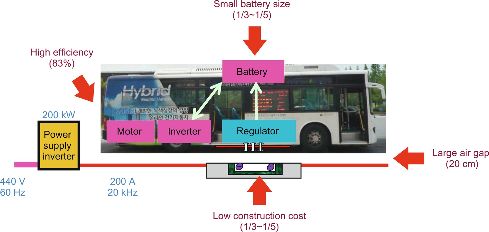
A stream of modern RPEVs is the OLEV, which has solved most of the remaining problems of the PATH team's work, as shown in Fig. 34.23. The OLEV project has started since 2009 by a research team led by KAIST, including the author, Korea [3–19]. Innovative coil designs and roadway construction techniques and all of the systems operating at a reasonably high frequency of 20 kHz made it possible to achieve the highest power efficiency of 83% at an output power of 60 kW with a large air gap of 20 cm and a fairly good lateral tolerance of 24 cm. Moreover, the power rail construction cost of the OLEV, which is responsible for more than 80% of the total deployment cost for RPEVs, has been dramatically reduced to at least a third of that of the PATH project. The primary current has been also reasonably mitigated as low as 200 A, and the battery size has been significantly reduced to 20 kWh, which can be further reduced by increasing the length of the power supply rails.
The first-generation (1G) concept demonstration car of OLEV, the second-generation (2G) OLEV buses, and the third-generation (3G) OLEV passenger car were developed and extensively tested at the test sites of KAIST since 2009, and three OLEV trains (3+G) had been successfully deployed at the Seoul Grand Park, Korea, since 2010. Two upgraded OLEV buses (3+G) were deployed at the 2012 Yeosu EXPO, Korea, and other two OLEV buses (3+G) have been in full operation at the main campus of KAIST since 2012. Recently, two OLEV buses (3+G) were firstly commercialized at a 48 km route in Gumi, Korea. The fourth-generation (4G) OLEV, showing more practical performances such as a very narrow rail width of 10 cm, a larger lateral displacement of 40 cm, lower EMF level, and lower power rail construction cost compared with the previous generation OLEV, has been also developed. The development of the fifth-generation (5G) OLEV is in progress, where an ultraslim S-type power supply coil of 4 cm rail width is proposed for power rail construction with much less cost and time [18,19].
34.3.3.2 2G OLEV
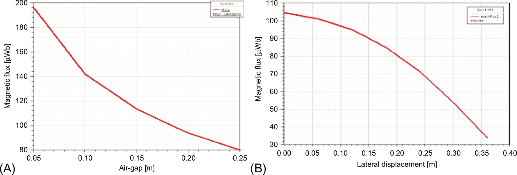
The 2G OLEV, announced on 14 July 2009, focused on drastically improving the air gap of the 1G OLEV without mechanical moving parts and finally achieved a 17 cm air gap, which meets road regulations, 12 cm in Korea and 16 cm in Japan. At the same time, it achieved a maximum efficiency of 72% and a maximum output power of 60 kW using 10 pickups. The power supply rail, where the width is 1.4 m and the total length is 240 m, is paved with asphalt to provide the same friction force as normal roads. In order to realize the 17 cm air gap, the U-type power supply rail and the flat pickup coil of IPTS have been developed, where the name “U-type” stems from the cross section of the power supply rail, as shown in Fig. 34.24. A pair of return power cables is used to mitigate the EMF from the power supply rail for the ICNIRP guidelines [35,36]. With the U-type power supply rail and I-type pickup coil, it is found that an effective area of the magnetic path between the power supply rail and the pickup coil increases as the air gap increases due to fringe effect, as shown in Figs. 34.24 and 34.25.

The cross section of the core plates of the power rail, as shown in Fig. 34.24, is significantly reduced by using the high operating frequency of 20 kHz, which is 50 times of the PATH team. The reason for selecting 20 kHz is that it is the lowest inaudible frequency, which mitigates the line voltage stress, as in (34.4). The upward magnetic flux generated from the pickup coil was appropriately shielded by an aluminum plate with a 5 cm distance.
34.3.3.3 3G OLEV
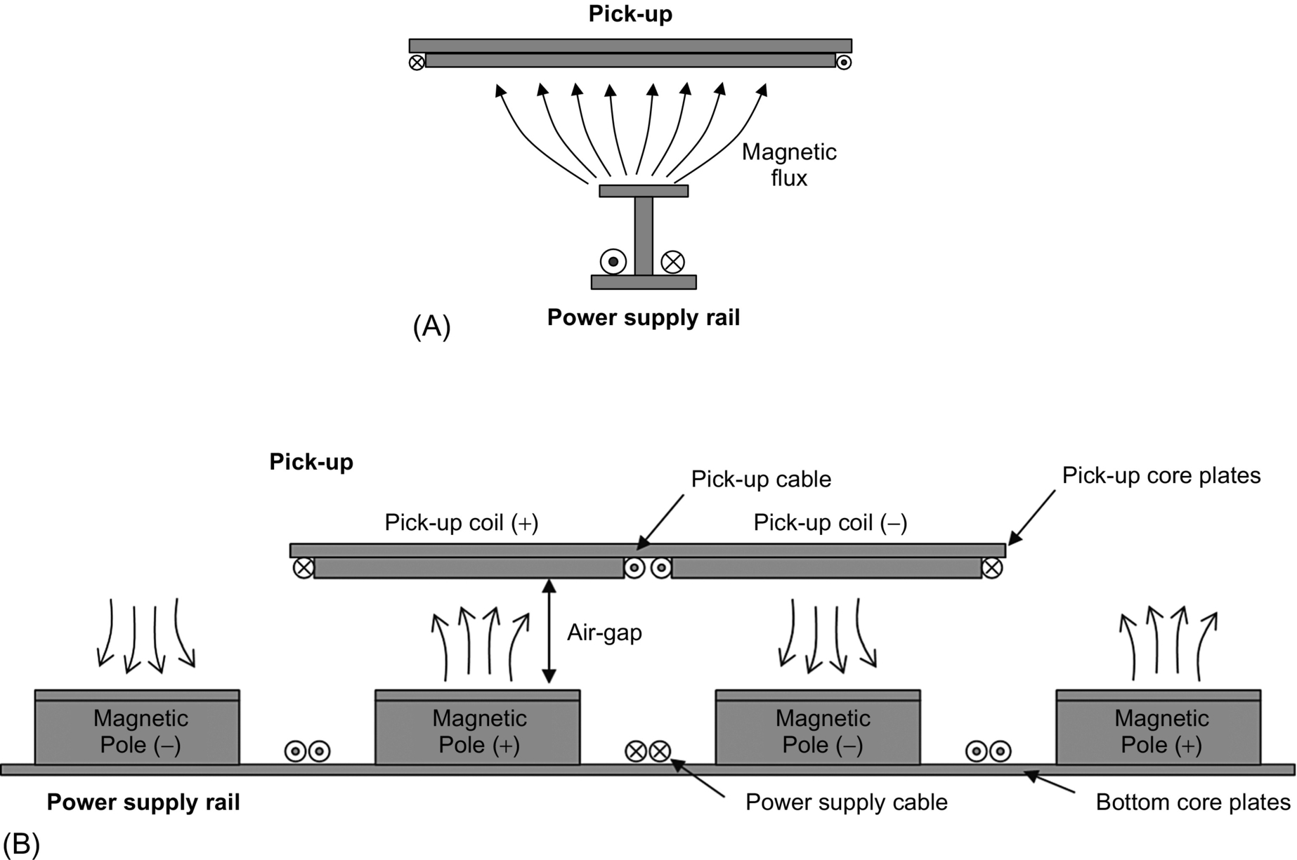
The 3G OLEV sports utility vehicle (SUV), announced on Aug. 14, 2009, adopted the W-type power supply rail and the flat pickup with overlapped double coils for higher power and increased lateral tolerance. Thus, the upward magnetic leakage flux from the pickup of 2G OLEV had been drastically mitigated by using the flat pickup core, which prohibits the magnetic flux between the power supply rail and pickup from leaking. The magnetic field shield such as an aluminum plate or additional space is no longer required.
The overall efficiency and air gap of the 3G OLEV were 71% and 17 cm, respectively, which are respectable, but slightly disappointing numbers; therefore, overall systems including a roadway rectifier and inverter, power supply rail, pickup, and onboard regulator were redesigned to achieve a maximum efficiency of 83% with a 20 cm air gap, and this new design was called the 3G+ OLEV.
The W-type power supply rail, as shown in Fig. 34.26, has many cores of “W” shape, where the total magnetic resistance becomes three-quarters smaller than that of the 2G OLEV for the same air gap, and this eventually leads to the increase of the output power from 6 to 15 kW for each pickup. Moreover, the width of the power supply rail is decreased to 70 cm, which is just a half of that of the 2G OLEV, and it can reduce the deployment cost of OLEV for commercialization. The EMF at 1.75 m distance meets the ICNIRP guideline because the two power cables of opposite polarity of magnetic flux cancel each other out [18,19].

One of the problems found during the development of 2G OLEV was the inherently weak structure of the power supply rail, where the core separates the concrete into two and undergoes severe mechanical stress from heavy vehicles. As a remedy for this mechanical weakness, bone structure core of the power supply rail, as shown in Fig. 34.26B, has been proposed, where the bone structure core is installed with the bone core-gap XD. Despite the large gap between cores, the magnetic flux does not decrease considerably, as shown in Fig. 34.26C.
In addition, during power rail road construction, concretes can percolate down through the bone structure cores. Therefore, the power supply rail, which is reinforced with two iron bars and in which power cables are protected by fiber-reinforced plastic (FRP) pipes, has almost the same endurance of concrete, as shown in Fig. 34.27. In practice, roadway construction of the power supply rail takes a few weeks, being affected by weather and debris, and this delay obstructs the commercialization of OLEV.

34.3.3.4 4G OLEV
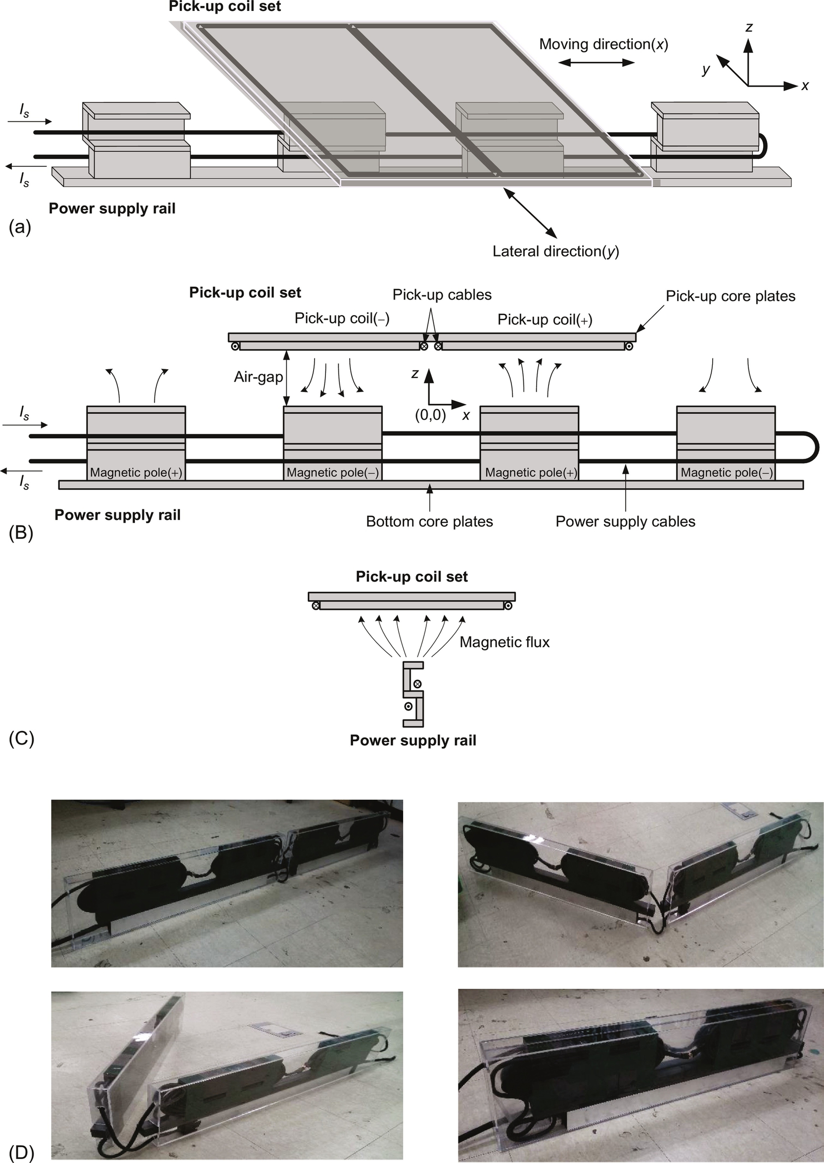
As shown in Fig. 34.28, the 4G OLEV, announced in 2010, has an innovative I-type structure of a power supply rail with a maximum output power of 27 kW for a double pickup coil having a 20 cm air gap and 24 cm lateral displacement. As shown in Fig. 34.28A, the I-type power supply rail, where the name “I-type” stems from its front shape, has only 10 cm width, which leads to a deployment cost reduction of 20% compared with the 3G OLEV. Unlike previous generations of OLEV, a very low EMF for pedestrians, as low as 1.5 μT at a distance of 1 m from the center of the power supply rail, can be obtained because the power supply rail has alternating magnetic poles along the road, as shown in Fig. 34.28B.
As shown in Fig. 34.29, the 4G OLEV adopted a module concept for the I-type power supply rail to reduce the deployment time within a few hours, which had been one of the drawbacks of the 3G OLEV. The I-type power supply module, which includes the power supply rail and capacitor banks inside, as shown in Fig. 34.29A, should be robust to high humidity and external mechanical impacts at least for 10 years, for example.

34.3.3.5 5G OLEV
To further reduce the construction cost and to increase the robustness of power supply rails, the 5G OLEV of ultraslim S-type core was recently proposed, which has an S-shape when viewed from the front, as shown in Fig. 34.30C.
The S-type power supply module has a width of only 4 cm, which has been decreased from the I-type width of 10 cm; hence, the S-type model leads to less construction cost and deployment time. Moreover, the S-type model makes it easier to fold itself, which means connecting power cables is no longer necessary after being deployed. The impact of deploying the S-type power supply modules on the surface of roads is now minimal, which fortunately does not change existing road operation conditions.
34.4 Design Considerations of Wireless Electric Vehicles
A few common design consideration issues applicable to both stationary and dynamic charging EVs are explained here. The issues are compensation, electric and magnetic circuit analyses, EMF cancel, and segmentation.
34.4.1 Compensation Circuit Design
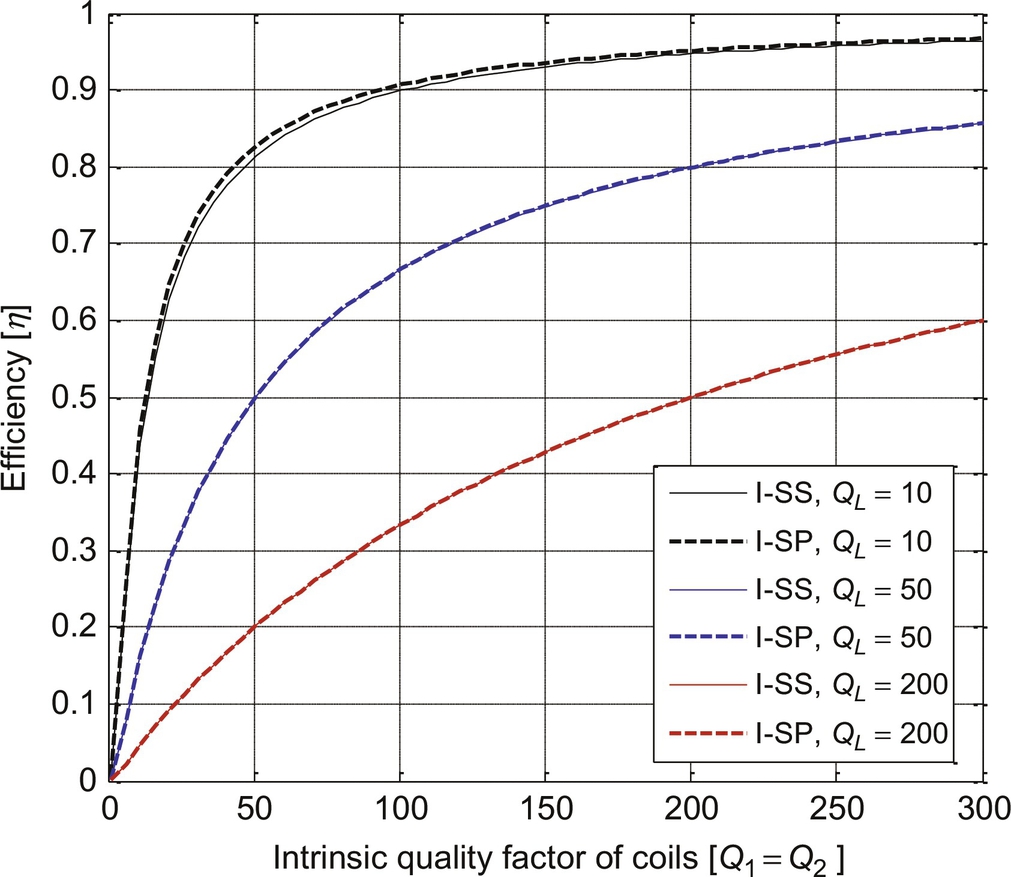
Due to large inductive reactances of IPT, capacitors are preferably adopted to nullify the total reactance and to resonate to a certain frequency for filtering out harmonics. One of widely used compensation circuits is two-capacitor type, called basic compensation circuit, as shown Fig. 34.31. There are eight possible circuit topologies for compensation depending on current (I) or voltage (V) source types and serial (S) or parallel (P) configurations. In case the magnetic coupling factor k between Tx and Rx coils varies a lot, the three conditions should be met for practical applications: (1) load-independent output voltage or output current, (2) k-independent compensation, and (3) allowance of no magnetic coupling (k=0).


It is identified that only I-SS and I-SP can satisfy all of the three criteria simultaneously among the eight compensation schemes [37]. I-SS has the voltage-source-type output characteristics, which enable large load current; whereas, I-SP has the current-source-type output characteristics, which enable high load voltage. Of course, other schemes may be also used if the three conditions are not needed.
Substantial equivalence and duality between I-SS and I-SP are found in the aspect of efficiency, power transfer characteristics, and voltage and current ratings of reactive components, as shown in Fig. 34.32. This means that there is no privilege between I-SS and I-SP, so we can freely choose compensation scheme according to large-current or high-voltage applications.
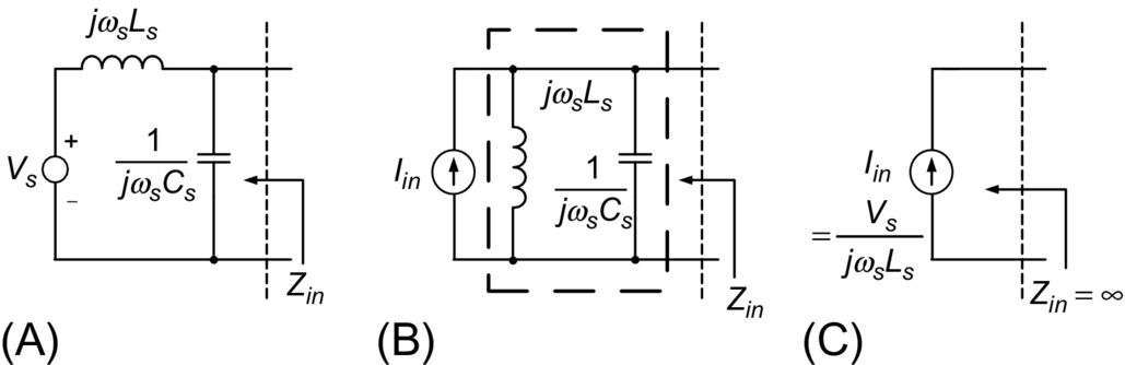
One of the ways to implement the current source of IPT is to make the current of a primary coil constant by feedback, as shown in Fig. 34.20. Another way of getting the current source is to use an LC filter for a given voltage source so that the Norton equivalent circuit has infinite output impedance when the source frequency is tuned to the resonance frequency, as shown in Fig. 34.33. This is known to be LCC topology of IPT [27,37], which has the current source input and voltage source output characteristics.
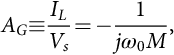
34.4.2 Gyrator Based Circuit Analysis
The electric analysis of IPT including compensation circuits is quite challenging because there are at least five energy storage circuit elements. Therefore, a powerful circuit analysis tool is recently invented, called gyrator-based circuit analysis by the author [38]. This method drastically simplifies the analysis process and makes it possible to get analytic results without cumbersome manipulation of equations. Applying Kirchhoff's voltage law on V1 and V2 in Fig. 34.34A gives us the following equations in the steady state of sinusoidal AC circuits:
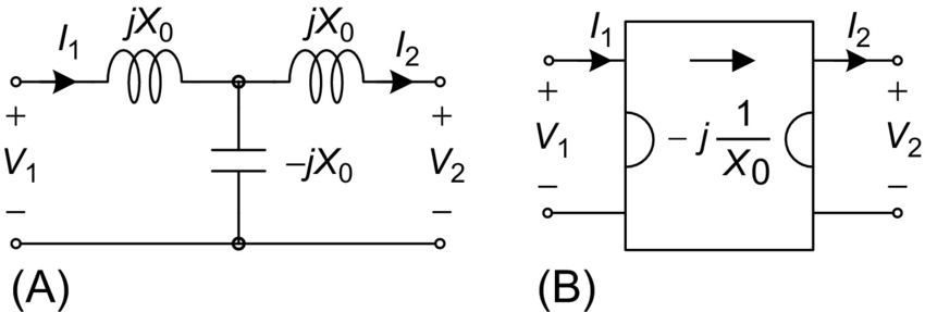
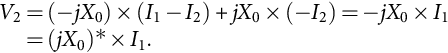
As shown in Fig. 34.34B, Eq. (34.5) describes the imaginary gyrator, first introduced in the literature [38].
As shown in Fig. 34.35, the T model of IPT can be decomposed into the imaginary gyrator and the primary and secondary inductances. This gyrator equivalent circuit is applied to the analysis of an example V-SS circuit of Fig. 34.36, where the series-series resonant circuits L1-C1 and L2-C2 are tuned to the source frequency, respectively.

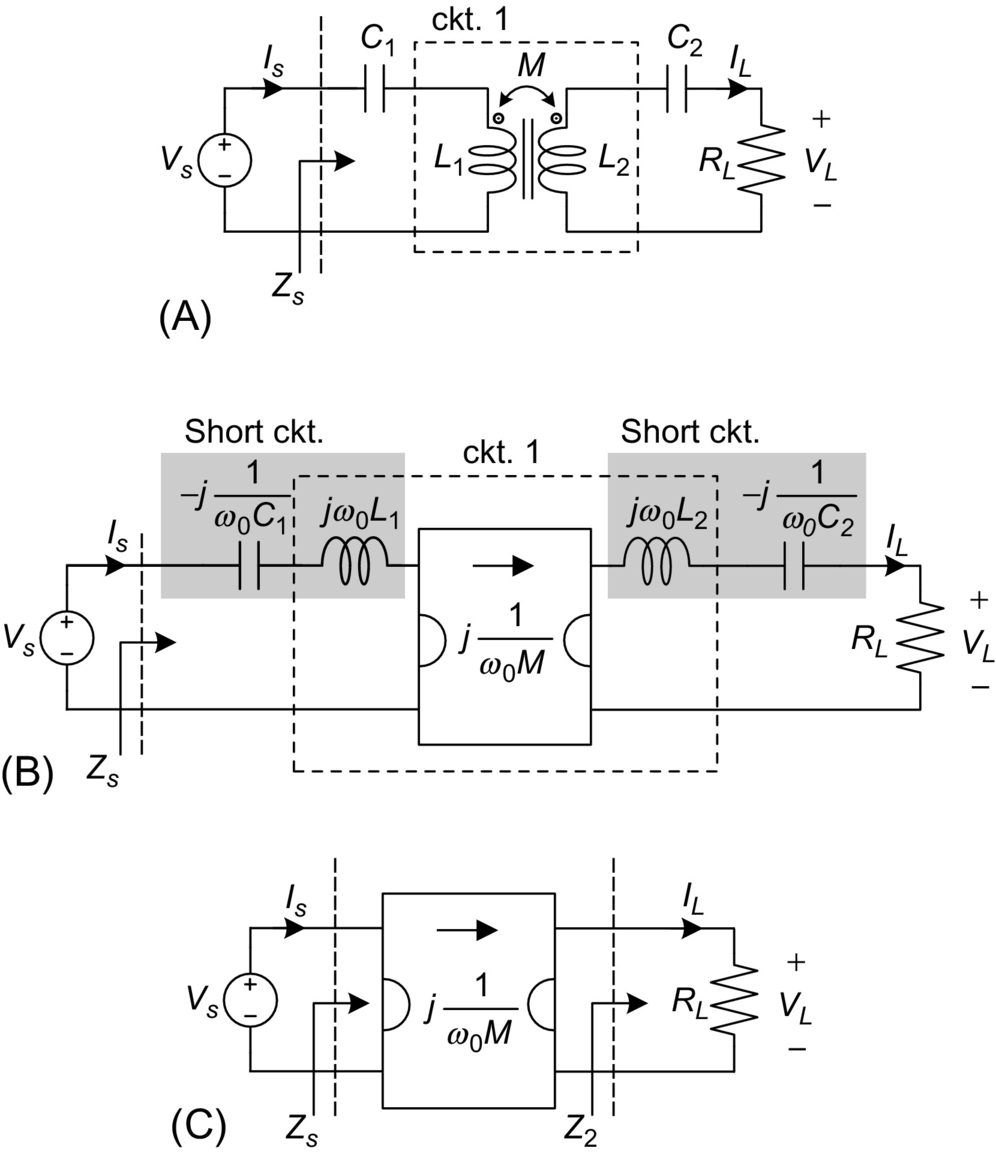
From the gyrator characteristics, the load current of V-SS is solely determined by the source voltage and independent of load resistance and load voltage as follows:

In this way, other features of the V-SS in Fig. 34.36 such as input power factor, voltage and current stresses of each component, and input and output impedances can be deduced from the equivalent gyrator circuit without using high-order matrix manipulation.
34.4.3 Magnetic Mirror Based Coil Design
In the coil design, we are quite often encountered to calculation of magnetic flux density, but you will readily see that there is nearly no available theoretical tool to finish your job. The difficulties of magnetic field calculation come from the complex interaction between current and magnetic material, which denies the application of Ampere's law that gives us the result only when appropriate current is given.
Fortunately, the magnetic flux density of an open magnetic circuit can be simply calculated by the magnetic mirror model [15], as shown in Fig. 34.37, where a reflected current at the same distance from the surface of a magnetic plate exists with a reduced amplitude as follows:
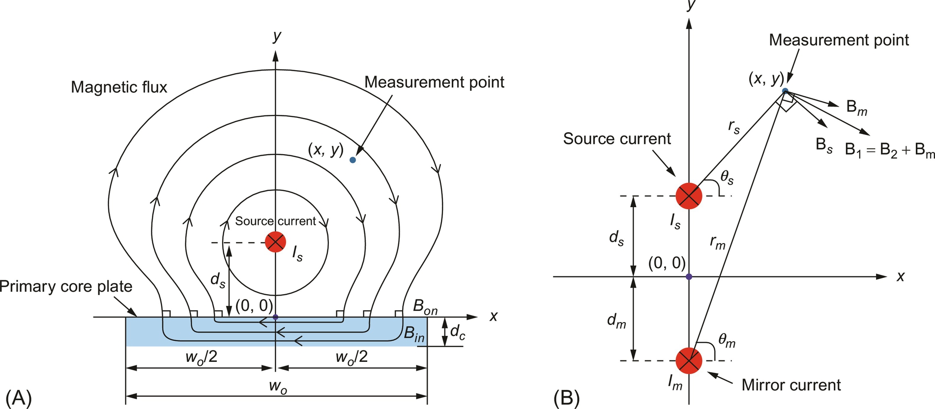

Then, the magnetic flux density of a mono coil B1 for a mirror current Im and a source current Is at an arbitrary measurement point (x, y) are obtained as follows:
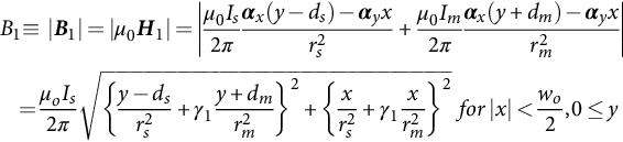
As identified from Fig. 34.37 and Eqs. (34.8)–(34.9), the magnetic flux density is at best doubled by the magnetic core for an open magnetic circuit. This is one of the backgrounds on no core use for some applications.
34.4.4 Generalized Active EMF Cancellation Methods
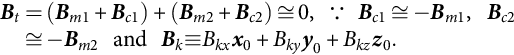
In the IPTS of OLEV, the total EMF, which is the summation of EMF generated by the power supply rail and the pickup coil, should be lower than the ICNIRP guideline for the safety of pedestrians. Among EMF cancellation methods [35,36,39–44], passive methods rely on the use of ferromagnetic materials, conductive materials, and selective surfaces for protecting against radio-frequency interference [39–41], which is found to be inadequate for OLEV. An active EMF cancellation design was applied to the RPEV of PATH team [1], where a canceling coil mitigates the EMF without RPEV. Note that the EMF is generated from both the power supply rail and pickup coil of the IPTS, as shown in Fig. 34.38; therefore, they must be canceled together without the need for accurate sensing of EMF and complicated control circuits, which is requisite for practical use.

A generalized active EMF design principle, which can be extended to any IPTS, has been developed [44], where there are three design methods: independent self EMF cancellation (ISEC), 3 dB dominant EMF cancellation (3DEC), and leakage-free EMF cancellation (LFEC). By adding an active EMF cancellation coil to each power supply rail and pickup coil without EMF sensing and control circuits, the EMF generated from each main coil can be independently canceled by their corresponding cancellation coils. Because the current of each cancellation coil is fetched from its corresponding main coil, the magnetic flux of a cancellation coil is in the phase of that of a main coil; hence, the EMF Bt becomes independent of both phase and load conditions as follows:
Together with ISEC, the 3DEC method is quite useful in practice for designing IPTS because it makes it possible to completely isolate the primary and secondary cancellation designs from each other.
For the full resonant IPTS that is very common in practice, the primary and secondary currents are in quadrature, that is, B1x ⊥ B2x, B1y ⊥ B2y, and B1z ⊥ B2z. Then, the total magnetic field Bt can be constrained to the ICNIRP guidelines so far as the dominating magnetic field B1 is less than 3 dB below the guideline as follows:

A design example for the 4G I-type IPTS based on the ISEC and 3DEC is shown in Fig. 34.39, where no cancellation coil was used for the power supply rail due to the low EMF generated from itself.
In case the EMF cancellation coils are involved in an unwanted magnetic linkage, as shown in Fig. 34.40, the induced load voltage drops; therefore, it is highly recommended to design the cancellation coils based on the LFEC method so that the magnetic linkage does not intersect them. The LFEC method can improve the load voltage as much as 21% [44].

34.4.5 Segmentation of Power rails
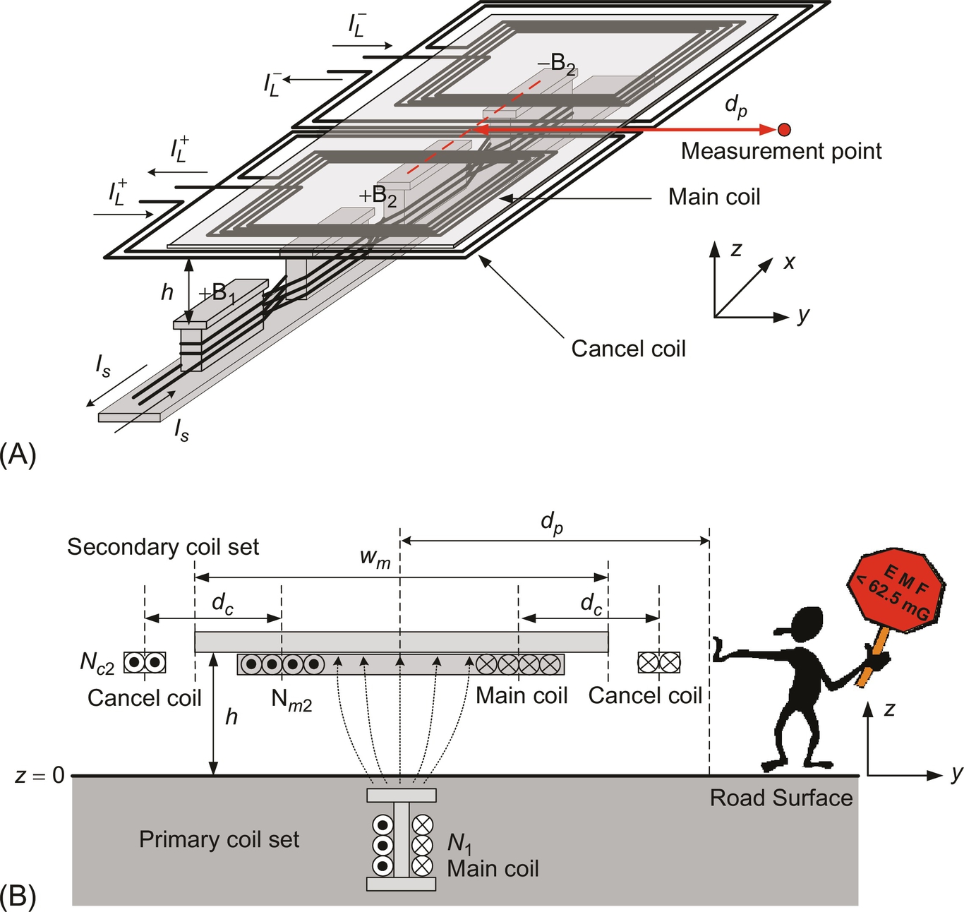
Unlike stationary charging EV, the RPEV needs its own roadway, where power supply rails should be activated when RPEVs are on the roadway, but they should be deactivated not to waste electric power and generate unwanted EMF for pedestrians; this is why the power supply rail is sometimes segmented into a few subrails. Each subrail can be activated by providing it with high-frequency current through a switch box from an inverter, as shown in Fig. 34.41.
The first segmented power supply rail developed for OLEV, as shown in Fig. 34.41A, was the centralized switching type composed of a few subrails, a bundle of supply cables, and a centralized switch box, where an inverter is connected to one of several pairs of supply cables through the switch box at a time. One of the demerits of the centralized one is that too many bundles of power cables are needed.
This is why the distributed switching power rail, as shown in Fig. 34.41B, was proposed, which is composed of a few subrails, a pair of common power supply cables, and multiple switch boxes located between two subrails.
Thus, the total length of the cable could be reduced compared with the centralized one, especially for a larger number of the cables. The distributed one, however, requires the common power supply cables, which increases the power rail construction cost and conductive power loss.
A recently proposed cross segmented power supply rail (X-rail) [16], consisting of segmented subrails, autocompensation switch boxes, control signal lines, and roadway harnesses, as shown in Fig. 34.41C, has the shortest length of power cable among the segmentations developed so far, and the inverter can drive multiple RPEVs, unlike the previous segmentations that activate only one subrail at a time.
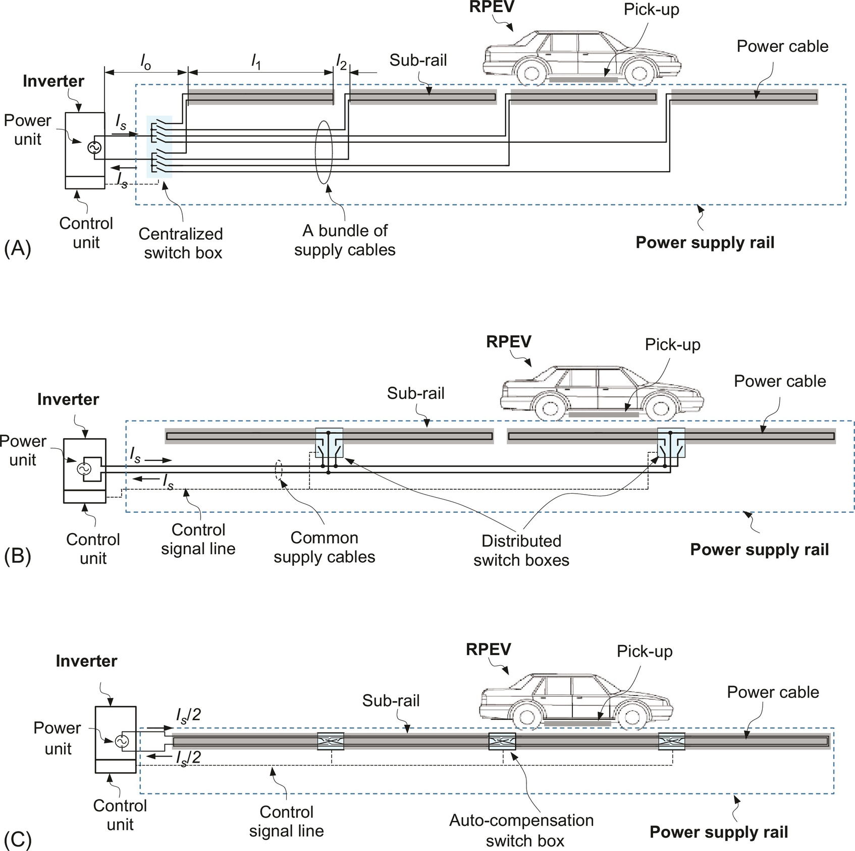
As shown in Fig. 34.42, the cable cost of the X-rail is nearly halved compared with the distributed switching, and the cable length reduction effect becomes dominant as the number of segmented subrails increases.
If applicable, nonsegmented power rail would be better than the segmented one, considering increased cost and complexities. One of the possible candidates is the autotuned IPTS, where power is delivered only when EVs are on the power supply coils.
34.5 Summary
The concepts of WPT and its practical applications to EVs are explained throughout the chapter. IPT for stationary and dynamic charging EVs is explained. The development of IPTS for RPEV including state-of-the-art technologies is explained in detail. RPEV is becoming a viable solution for future transportation as the first commercialized online EV has demonstrated its validity.