
Flexible AC Transmission Systems
Edson H. Watanabe Electrical Engineering Department, COPPE/Federal University of Rio de Janeiro, Rio de Janeiro, Brazil
Francisco K. deAraújo Lima Electrical Engineering Department, Federal University of Ceara, Fortaleza, Brazil
Robson F. daSilva Dias Electrical Engineering Department, Polytechnic School and COPPE/Federal University of Rio de Janeiro, Rio de Janeiro, Brazil
Maurício Aredes Electrical Engineering Department, Polytechnic School and COPPE/Federal University of Rio de Janeiro, Rio de Janeiro, Brazil
Pedro G. Barbosa Electrical Engineering Department, Federal University of Juiz de Fora, Juiz de Fora, Brazil
Silvangela L.S. Lima Barcelos Electrical Engineering Department, Federal University of Maranhão, São Luís, Brazil
Gilson Santos, Jr. Forbes Bros Ltd, Edmonton, Alberta, Canada
Abstract
This chapter presents the basic operation principles of FACTS devices. Starting with a brief introduction on the concept and its origin, the text then focuses on the ideal behavior of each basic shunt and series of FACTS device. Guidelines on the synthesis of the first generation of these devices based on thyristors are presented, followed by the newer generations of FACTS devices based on self-commutated semiconductor switches.
Keywords
FACTS; STATCOM; SSSC; UFFC; SVC; TCR
28.1 Introduction
In 1988, Hingorani [1] published a paper entitled “Power Electronics in Electric Utilities: Role of Power Electronics in Future Power Systems,” proposing the extensive use of power electronics for the control of ac systems, which resulted in the flexible ac transmission system or the FACTS concepts [2]. The basic idea was to obtain ac systems with a high level of control flexibility, as in high-voltage direct current (HVDC) systems [3] based on the use of the thyristor and the self-commutated (controllable turn-on and turn-off) silicon (Si) semiconductor devices, such as gate turn-off thyristors (GTOs), insulated gate bipolar transistors (IGBTs), and integrated gate-controlled thyristors (IGCTs) [4,5], or silicon carbide (SiC)-based devices [6], which were not yet developed at that time.
The switching characteristics of thyristors—controlled turn-on and natural turn-off—are appropriate for using in line-commutated converters, such as in conventional HVDC transmission systems with a current source in the dc side. In this application, the technology for series connection of thyristors is very important due to the high-voltage characteristics of the transmission voltage. This is a well-known technology. Maximum breakdown voltage and current conduction capabilities are around 8 kV and 4 kA, respectively. These are some features that make thyristors important for very high-power applications, although they present some serious drawbacks, such as the lack of controlled turn-off capability and low switching speeds.
Self-commutated switches are adequate for use in converters where turn-off capability is necessary. The device with highest ratings in this group was, for a long time, the GTO with maximum switching capability of 6 kV and 6 kA. At present, there are IGBTs with ratings in the range of 6.5 kV to 3 kA and IGCTs with switching capability of about 6 kV and 4 kA. The GTOs and IGCTs are devices that normally need small inductor for limiting the rate of change of turn-on current (di/dt). Normally, GTOs also need a snubber circuit for limiting the rate of change of voltage (dv/dt).
The GTOs, IGCTs, and IGBTs are the most used options for self-commutated high-power converters. Because the switching time of these devices is in the microsecond range (or below), their series connection is more complicated than in the case of thyristors. However, there are examples of series connections of various GTOs or IGCTs, and in the case of IGBTs, the number of series connected devices can go as high as 32 [7]. It is worth to note that GTOs are not used in new projects anymore.
Because of the commutation nature of the thyristors, the converters used in HVDC systems are of the current source type [8]. On the other hand, the force-commutated converters using the self-commutated devices are basically of the voltage source type. More details about current source and voltage source converters can be found in many power electronics books, for example, Refs. [3,8].
28.2 Ideal Shunt Compensator
A simple and lossless ac system is composed of two ideal generators, and a short transmission line, as shown in Fig. 28.1, is considered as basis to the discussion of the operating principles of a shunt compensator [9]. The transmission line is modeled by an inductive reactance XL. In the circuit, a continuously controlled voltage source is connected in the middle of the transmission line. It is assumed that the voltage phasors VS and VR have the same magnitude, V, and are phase-shifted by δ. The subscript “S” stands for “source” and “R” stands for “receptor.” Fig. 28.2 shows the phasor diagram of the system given in Fig. 28.1 in which the compensation voltage phasor VM has also the same magnitude as VS and VR, and its phase is exactly (−δ/2) with respect to VS and (+δ/2) with respect to VR.
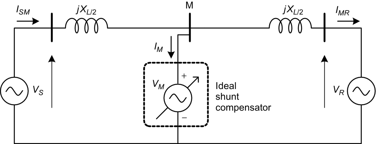
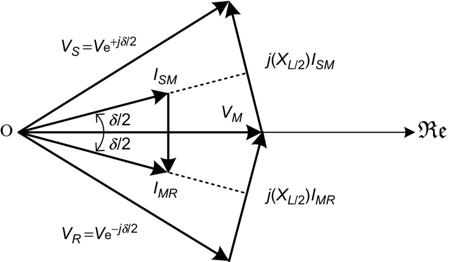
In this situation, the current ISM flows from the source and the current IMR flows into the receptor. The phasor IM is the resulting current flowing through the ideal shunt compensator; Fig. 28.2 shows that this current IM, in this case, is orthogonal to the voltage VM, which means that the ideal shunt compensator voltage source does not have to generate or absorb active power and have only reactive power in its terminals.
From Fig. 28.2 and knowing that no active power flows to or from the ideal shunt compensator, it is possible to calculate the power transferred from VS to VR that is given by

where PS is the active power flowing from the source.
If the ideal shunt compensator were not present, the transferred power would be given by
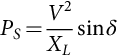
Since 2 sin(δ/2) is always greater than sin δ for δ in the range of [0, 2π], the ideal shunt compensator does improve the power transfer capability of the transmission line. This voltage source is in fact operating as an ideal reactive power shunt compensator.
If the phase angle between VM and VS is different from δ/2 (as shown in Fig. 28.3), the power flowing through VM has both active and reactive components.

With the characteristics of the ideal shunt compensator, presented above, it is possible to synthesize power electronic-based devices to operate as active or reactive power compensators. This is discussed in the following sections. It will be seen that the requirements of the device synthesis with actual semiconductor switches for the situations of reactive or active power compensation are different because of the need of energy storage element or energy source if active power is to be drained or generated by the shunt compensator.
28.3 Ideal Series Compensator
Similar to the previous section, the ideal series compensator is modeled by a voltage source for which the phasor is VC connected in the middle of a lossless transmission line as shown in Fig. 28.4
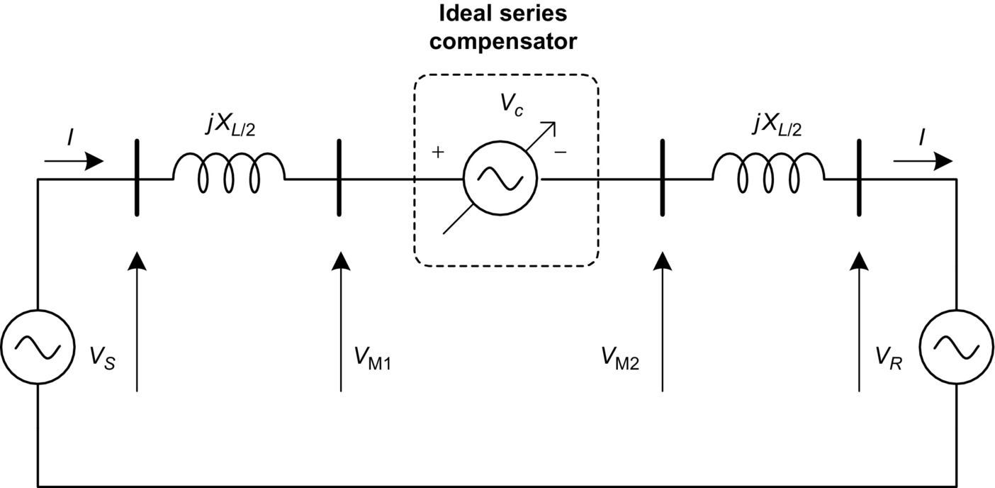
The current flowing through the transmission line is given by
where ![]() .
.
If the ideal series compensator voltage is generated in such a way that its phasor VC is in quadrature with line current I, this series compensator neither supplies nor absorbs active power. As discussed earlier, power at the series source is only reactive, and the voltage source may, in this particular case, be replaced by capacitive or inductive equivalent impedance. Then, the equivalent impedance is given by
where
is the compensation factor and XComp is the series equivalent compensation reactance, negative if capacitive and positive if inductive. In this case, the compensation voltage is given by
and the transmitted power is equal to
Eq. (28.7) shows that the transmitted power can be considerably increased by series compensation, choosing a proper compensation factor s. The reactive power at the series source is given by
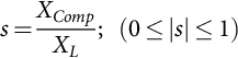
The left-hand side of Fig. 28.5A shows the phasor diagram of the system shown in Fig. 28.4 without the ideal series compensator. On the right-hand side of the Fig. 28.5A, the voltage phasor VL on the line reactance XL and the compensator voltage phasor VC are shown for a given compensation level, assuming that this voltage VC corresponds to a capacitive compensation. In this case, the line current phasor leads voltage phasor VC by 90 degrees, and the total voltage drop in the line ![]() is larger than the original voltage drop VL. The current flowing in the line is larger after compensation than before. This situation shows the case where the series compensator is used to increase power flow.
is larger than the original voltage drop VL. The current flowing in the line is larger after compensation than before. This situation shows the case where the series compensator is used to increase power flow.
The left-hand side of the Fig. 28.5B shows the same noncompensated situation as in the previous case. On the right-hand side, the case of an equivalent inductive compensation is shown. In this case, the compensation voltage VC is in phase with the line drop voltage VL, producing an equivalent total voltage drop VZ smaller than in the original case. As a result, the current phasor I flowing in the line is smaller than before compensation. This kind of compensation might be interesting in the case that the power flowing through the line has to be decreased. In either capacitive or inductive compensation modes, no active power is absorbed or generated by the ideal series compensator.
Fig. 28.6 shows an ac system with an ideal generic series compensation voltage source VC for the general case where it may not be in quadrature with the line current. In this case, the compensator can fully control the phase difference between the two systems, thus controlling the active and reactive power exchanged between them. However, in this case, the compensation voltage source VC may have to absorb or generate active power (PC) and control the reactive power (QC).

Fig. 28.7 shows the phasor diagram of this ideal generic series compensator. This figure also shows a dashed-line circle with the locus of all possible positions that the compensation voltage VC could take, assuming that the magnitude shown for this voltage is its maximum. Naturally, if the sum of the compensation voltage and the source voltage VS is on the circle, the magnitude of VS1 may be smaller or larger than the magnitude of VS.
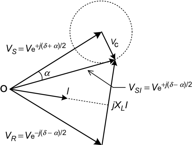
The compensation voltage VC can be added to the VS in a way that the resultant voltage VS1 has the same magnitude of VS but with a phase shifted by an angle α. In this case, the series compensator can be called as a phase-shifter compensator, and the power flowing through the transmission line (see Fig. 28.6) is expressed below:
Eq. (28.9) shows that transmitted power increases as the phase difference (![]() ) reaches 90 degrees. However, its maximum value is the same as in the case of no compensation. The difference is that with this compensator, the system power angle, and angle difference between the two voltage sources at the terminals of the line can be controlled faster than the conventional way, that is, by controlling the synchronous generator.
) reaches 90 degrees. However, its maximum value is the same as in the case of no compensation. The difference is that with this compensator, the system power angle, and angle difference between the two voltage sources at the terminals of the line can be controlled faster than the conventional way, that is, by controlling the synchronous generator.
In Fig. 28.7, voltage VC may have any phase angle with respect to line current. Therefore, it may have to supply or absorb active power and control reactive power. As in the case of the shunt device, this feature must also be taken into account in the synthesis of the actual devices. As a first approximation, when the goal is to control active power flowing through the medium- or short-length transmission lines, compensator location seems to be a question of convenience.
Fig. 28.8 summarizes the active power transfer characteristics in a transmission line as a function of the power angle, δ, as shown in Figs. 28.1 and 28.2, for the cases of the line without compensation, line with series or shunt reactive power compensation, and line with phase-shift compensation (generic series compensation). These characteristics are drawn on the assumption that the source voltages VS and VR (see Fig. 28.2) have the same magnitude. A 50% series compensation (s=0.5) as defined in Eq. (28.4) presents a significant increase in the line power transfer capability.

As shown in Fig. 28.8, in general, series compensation is the best choice for increasing power transfer capability. The phase-shifter compensator is important to connect two systems with excessive or uncontrollable phase difference. It does not increase power transfer capability significantly; however, it may allow the adjustment of large or highly variable phase differences. The shunt compensator does not increase power transfer capability in a significant way in its normal operating region, where the angle δ is naturally below 90 degrees and in general around or less than 30 degrees. The great importance of the shunt compensator is the increase in the stability margin, as explained in Fig. 28.9.
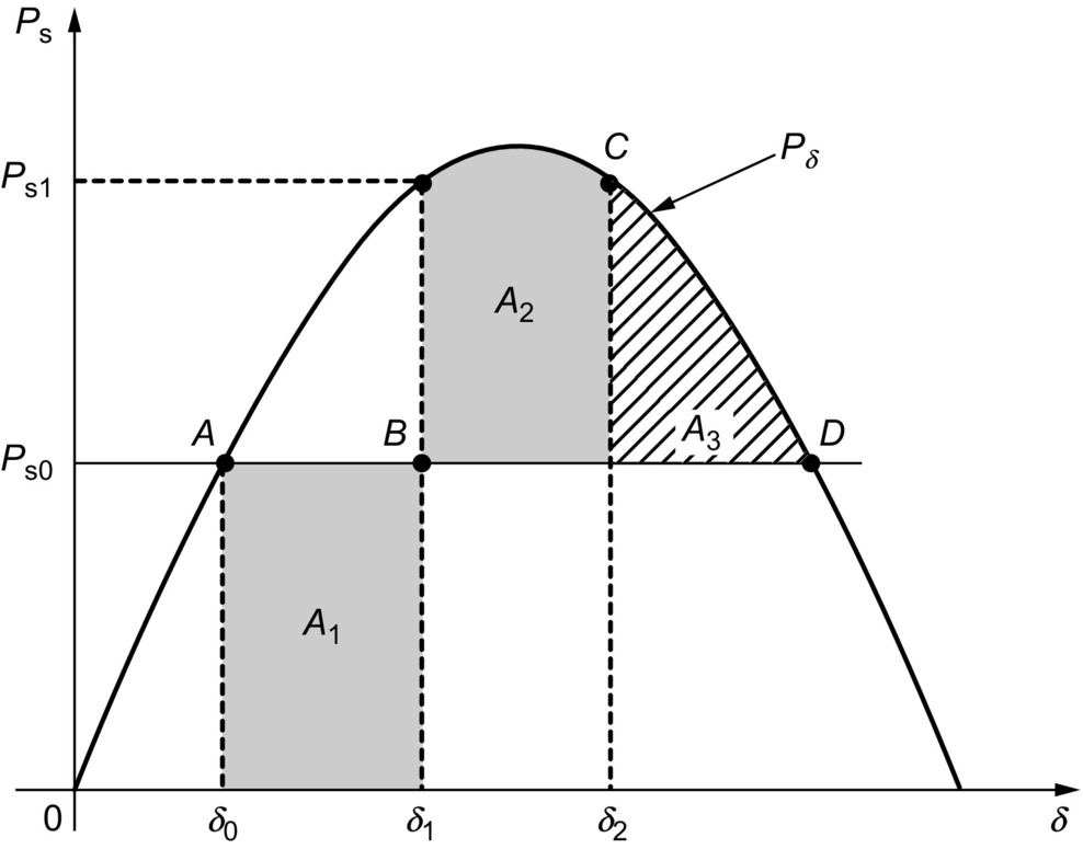
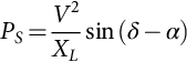
Fig. 28.9 shows the power transfer characteristics ![]() of a transmission line, which is first assumed to be transmitting power PS0 at phase angle δ0. If a problem happens in the line (e.g., a fault), the turbine that drives the generator cannot change its mechanical power input immediately even if there is no power transmission for a short time. This situation accelerates the generator, increasing its frequency and leading to an increase of the phase angle δ to δ1. If the line restarts operation at the instant corresponding to this phase angle δ1, the transmitted power will be PS1, which is larger than PS0 and decelerates the turbine or generator. The area A1 corresponds to the energy that accelerated the turbine. As the frequency gets higher than the rated frequency at (PS1, δ1), the phase angle will increase up to δ2, where the area A2 is equal to the area A1. If the area given by the A2 plus A3 is larger than A1, the system is said to be dynamically stable. On the contrary, if it is not possible to have an area A2 equal to A1, the system is said to be unstable. An unstable situation is shown in Fig. 28.10 in which the system is the same as in Fig. 28.9 but assuming a longer interval with no power transmission. In this case, the turbine or generator accelerates more than that in Fig. 28.9, and the phase angle δ increases above its critical value δc, which is slightly less than 90degrees reaching δ1. Therefore, the area below the Pxδ curve to decelerate the system is not enough leading to an unstable system because A2 is smaller than A1 and the frequency does not return to its original value.
of a transmission line, which is first assumed to be transmitting power PS0 at phase angle δ0. If a problem happens in the line (e.g., a fault), the turbine that drives the generator cannot change its mechanical power input immediately even if there is no power transmission for a short time. This situation accelerates the generator, increasing its frequency and leading to an increase of the phase angle δ to δ1. If the line restarts operation at the instant corresponding to this phase angle δ1, the transmitted power will be PS1, which is larger than PS0 and decelerates the turbine or generator. The area A1 corresponds to the energy that accelerated the turbine. As the frequency gets higher than the rated frequency at (PS1, δ1), the phase angle will increase up to δ2, where the area A2 is equal to the area A1. If the area given by the A2 plus A3 is larger than A1, the system is said to be dynamically stable. On the contrary, if it is not possible to have an area A2 equal to A1, the system is said to be unstable. An unstable situation is shown in Fig. 28.10 in which the system is the same as in Fig. 28.9 but assuming a longer interval with no power transmission. In this case, the turbine or generator accelerates more than that in Fig. 28.9, and the phase angle δ increases above its critical value δc, which is slightly less than 90degrees reaching δ1. Therefore, the area below the Pxδ curve to decelerate the system is not enough leading to an unstable system because A2 is smaller than A1 and the frequency does not return to its original value.
Looking at Fig. 28.8, it is possible to see that depending on the operating point, all three compensation methods increase the stability margin as the area under the curve of transmitted power Pδ versus phase angle δ is increased. The ideal shunt compensator is the one that most increases this area, and thus, it is said to be the best option to increase the stability margin.
28.4 Synthesis of FACTS Controllers
It has been stated that the synthesis of the compensators presented in Sections 28.2 and 28.3 can be achieved with thyristors or self-commutated switches. Each type of switches (thyristor or self-commutated) leads to controllers with different operating principles and synthesis concepts, and hence, they should be discussed separately. Terms and definitions for most of the FACTS controllers are given in Ref. [10].
Thyristor-based FACTS controllers use line or natural commutation together with large passive energy storage elements (capacitors or reactors). On the other hand, controllers based on self-commutating switches use gate-controlled commutation. In general, it is said that the first generation of FACTS devices is based on conventional line-commutated thyristors, and the subsequent generations are based on gate-controlled devices or self-commutated switches. The most important FACTS controllers based on thyristors and self-commutating controllers are presented in the following sections.
28.4.1 Thyristor-Based FACTS Controllers
28.4.1.1 Thyristor-Controlled Reactor
The most used thyristor-based FACTS controller is the thyristor-controlled reactor (TCR) as shown in Fig. 28.11A. This is a shunt compensator that produces an equivalent continuous variable inductive reactance by using phase-angle control. Fig. 28.11B shows the voltage and current waveforms of the TCR. The current is controlled by the firing angle α; the magnitude of the fundamental current component can be larger or smaller depending on the angle α, which can vary from 90 to 180 degrees measured from the zero crossing of the voltage. At ![]() , the reactor is fully inserted in the circuit, and for
, the reactor is fully inserted in the circuit, and for ![]() , the reactor is completely out of the circuit. Fig. 28.12 shows the equivalent admittance of the TCR as function of the firing angle α. Naturally, this admittance is always inductive.
, the reactor is completely out of the circuit. Fig. 28.12 shows the equivalent admittance of the TCR as function of the firing angle α. Naturally, this admittance is always inductive.


28.4.1.2 Thyristor-Switched Capacitor
Fig. 28.13 shows the thyristor-switched capacitor (TSC). The word “controlled” used in the case of the reactor is substituted by “switched” because the thyristor is turned on only when zero-voltage switching (ZVS) condition is possible. This means that the voltage across the thyristor terminals has to be zero at the turn-on instant. In practical cases, it may be slightly positive because thyristors need positive anode-cathode voltages to be triggered (positive anode-cathode voltage during turn-on); however, if this voltage is too high, it can produce a large current spike that can damage the thyristors. Therefore, due to this switching characteristic, the thyristors can only connect the capacitor to the grid or disconnect it. Consequently, only steplike control is possible, and a continuous control is not possible. The capacitor connection to or disconnection from the grid is normally performed at very low frequencies, and the harmonics, when they appear, are not a serious concern.
28.4.1.3 Static Var Compensator
The use of the TCR shown in Fig. 28.11 or the TSC shown in Fig. 28.13 allows only continuous inductive compensation or discontinuous capacitive compensation. However, in most applications, it is desirable to have continuous capacitive or inductive compensation. The static var compensator (SVC) is generally designed to operate in both inductive and capacitive continuous compensation [11,12]. It may be used for reactive power compensation for either voltage regulation or power factor correction. The basic three-phase SVC scheme is comprised of a three-phase TCR parallel connected to a capacitor bank. The TCR serves as the controller basis for the conventional SVC.
Fig. 28.14 shows a single-line diagram of an SVC, where the TCRs are Δ connected and the capacitors are Y connected. The circuit does not show the filters that are normally needed due to the switching-generated harmonics. In some cases, the capacitor bank can be a fixed capacitor parallel connected to a TSC in order to get more flexibility in terms of control range.

The capacitance of the SVC is calculated in such a way as to generate the maximum capacitive reactive power that it has to control. This condition is achieved when the thyristors are turned off (![]() ). On the other hand, the maximum reactive power of the TCR inductor has to be greater than the reactive power of the capacitor bank. In this way, the SVC can control the reactive power from capacitive to inductive. The maximum inductive reactive power is given for the case when the thyristors are turned on at minimum firing angle (
). On the other hand, the maximum reactive power of the TCR inductor has to be greater than the reactive power of the capacitor bank. In this way, the SVC can control the reactive power from capacitive to inductive. The maximum inductive reactive power is given for the case when the thyristors are turned on at minimum firing angle (![]() ). The SVC can control reactive power from maximum capacitive for
). The SVC can control reactive power from maximum capacitive for ![]() to maximum inductive for
to maximum inductive for ![]() . Thus, the SVC represents an adjustable fundamental frequency susceptance to the ac network, controlled by the firing angle of the TCR thyristors (
. Thus, the SVC represents an adjustable fundamental frequency susceptance to the ac network, controlled by the firing angle of the TCR thyristors (![]() ).
).
The SVC is well known, and many examples of successful applications can be found around the world.
Due to the once-per-cycle thyristor firing with phase-angle control, current with low-order harmonic components appears and Y-Δ transformers and passive filters may be needed to eliminate part of them. Three sets of TCRs connected in the Δ side of Y-Δ transformers form a conventional six-pulse TCR. To minimize harmonic generation, it is common to have two sets of transformers connected in Y-Δ and Δ-Δ with the TCR connected in the Δ side forming a 12-pulse TCR.
28.4.1.4 Thyristor-Switched Series Capacitor
Fig. 28.15 shows the thyristor-switched series capacitor (TSSC). In this controller, the thyristors should be kept untriggered so as to connect the capacitors in series with the transmission line. If the thyristors are turned on, the capacitor is bypassed. Thyristors must be turned on at a zero-voltage condition (ZVS), as it occurs in the case of the TSC, to avoid current spikes in the switches. An example of an application based on this concept is presented in Ref. [13].

This compensation system has the advantage of being very simple. However, it does not allow continuous control. If the connection or disconnection of the capacitors is to be made at sporadic switching, it can be said that no harmonic problem occurs. Depending on the frequency the thyristors are switched, harmonic or subharmonics may appear. In this arrangement, it is interesting to choose a number of capacitors in such a way that many different combinations can be achieved. For example, if the total number of capacitors is three, they could have impedance proportional to 1, 2, and 3. Therefore, by combining these values, it is possible to obtain equivalent capacitive impedance proportional to 1, 2, 3, 4, 5, and 6.
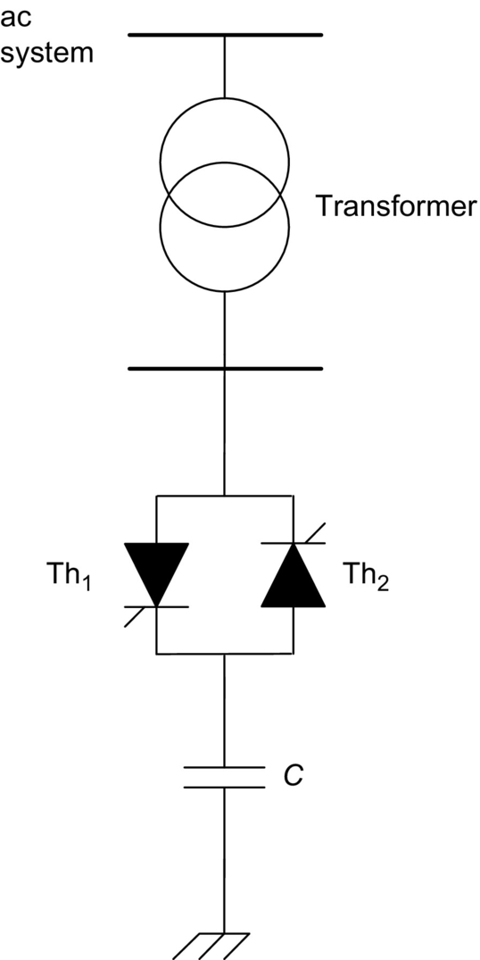
28.4.1.5 Thyristor-Controlled Series Capacitor
Fig. 28.16 shows the thyristor-controlled series capacitor (TCSC). In this figure, the transmission line and the voltage sources at its ends are represented by a current source because this is the actual behavior of most of the transmission system. This compensator is also based on the TCR that was first developed for shunt connection. When the TCR is used connected in series with the line, it has to be always connected in parallel with a capacitor because it is not possible to control the current if the equivalent of the transmission line and the sources is a current source. This circuit is similar to the conventional SVC with the difference that the TCSC is connected in series with the line. In this compensator, the equivalent value of the series connected reactor can be continuously controlled by adjusting the firing angle of the thyristors. As a consequence, this device presents a continuously controllable series capacitor. Various practical systems based on this concept are under operation around the world [13–15]. This device has been used for power flow control and power oscillation damping.

Fig. 28.17 presents the current and voltage waveforms in the TCSC, showing that although there is a large amount of harmonics in the capacitor and reactor currents, capacitor voltage is almost sinusoidal. In actual applications, these harmonics are not a serious concern, and they are filtered by the capacitor itself and by the transmission line impedance.
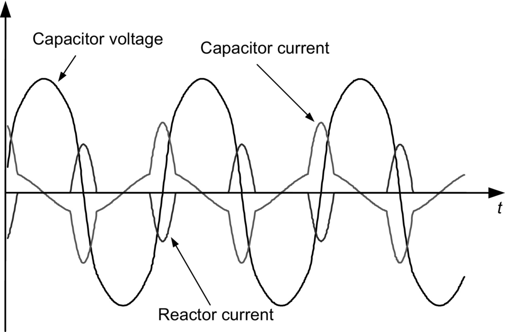
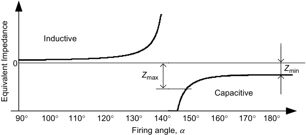
Fig. 28.18 shows the equivalent impedance of the TCSC as a function of the firing angle α. This figure shows that this controller has both capacitive and inductive characteristic regions divided by a resonant region. In the example shown in this figure, the resonance happens for α around 145 degrees. In normal operation, the TCSC is controlled in the capacitive compensation region where its impedance varies from its minimum value Zmin for firing angle ![]() and its maximum safe value Zmax for α around 150 degrees. Operation with α close to the resonance region is not safe. This device can operate also in the inductive region, but in this case, normally, it is used only when
and its maximum safe value Zmax for α around 150 degrees. Operation with α close to the resonance region is not safe. This device can operate also in the inductive region, but in this case, normally, it is used only when ![]() to decrease power transfer capability of the transmission line.
to decrease power transfer capability of the transmission line.
28.4.1.6 Thyristor-Controlled Phase Angle Regulator
The thyristor-controlled phase-angle regulator (TCPAR), shown in Fig. 28.19 as an example, may improve considerably the controllability of a utility of power transmission system. In this figure, only the control of phase “a” is detailed. The series voltage generated in phase “a” comes from three secondary windings of a transformer whose primary side is connected between phases “b” and “c.” Each of the three secondary windings can be connected in series with the line through the thyristors' switching. The thyristors are connected in antiparallel, forming bidirectional naturally commutated switches. By turning on a set of thyristors, a voltage whose magnitude can be controlled by phase control is connected in series with the transmission line. The number of secondary windings is chosen as to decrease harmonic content of the series compensation voltage (Fig. 28.17).
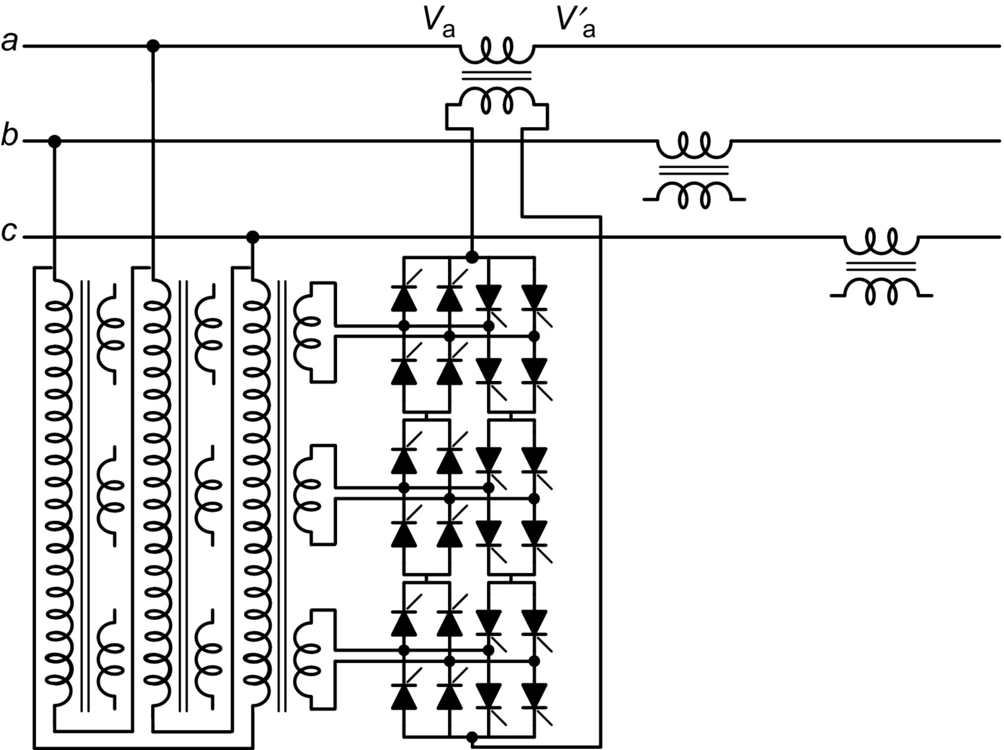
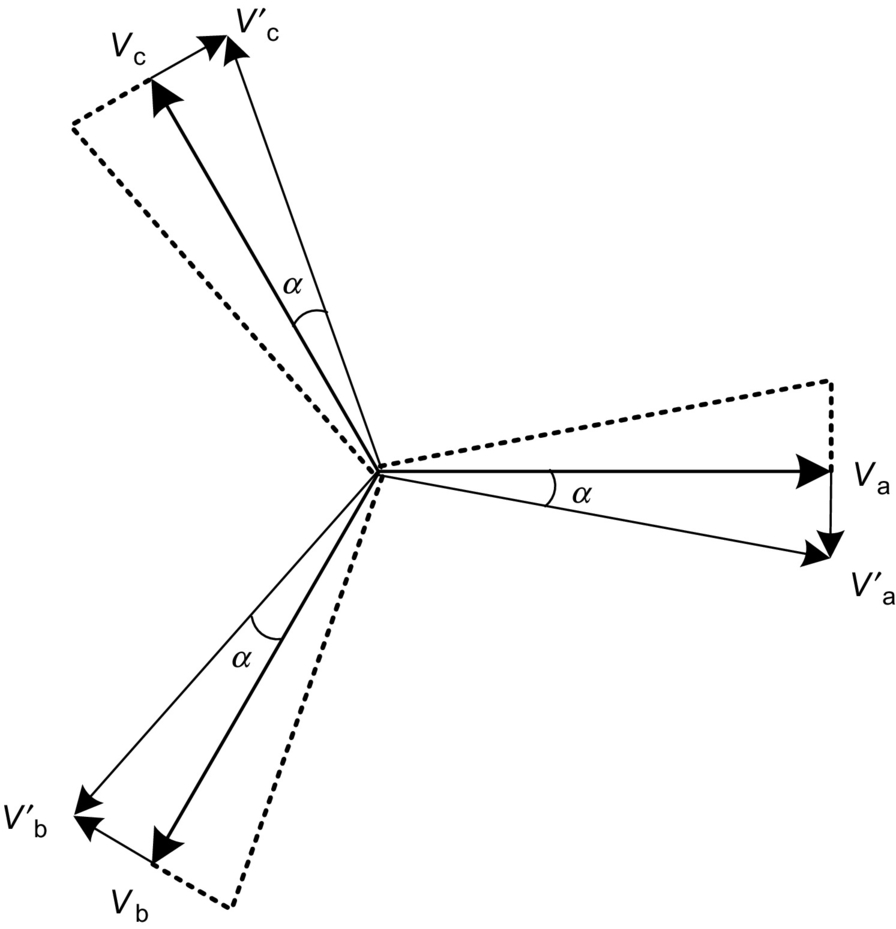
The TCPAR in Fig. 28.19 has some peculiarities that should be pointed out. One of them is that active power can only flow from the shunt to the series windings. The compensation voltage phasor, as shown in Fig. 28.20, has a limited range of variation; in the case of phase “a,” its locus is along a line orthogonal to Va because the injected voltage is in phase with the voltage ![]() . As a consequence, it is not possible for the TCPAR to generate a compensating voltage phasor whose locus is a circle, as shown in Fig. 28.7, for the case of an ideal generic series compensator.
. As a consequence, it is not possible for the TCPAR to generate a compensating voltage phasor whose locus is a circle, as shown in Fig. 28.7, for the case of an ideal generic series compensator.
Other configuration of phase shifters can be found in the literature, for example [16,17].
28.4.2 FACTS Controllers Based on Self-Commutated Switches
There are various different types of FACTS controllers based on self-commutated switches, and the names used here are in accordance with the names published in Ref. [10]. Some of them are newer controllers and are not in that reference. In this case, the name used is the same as it appears in the literature. In Ref. [2], it is possible to find most of the details of FACTS controllers.
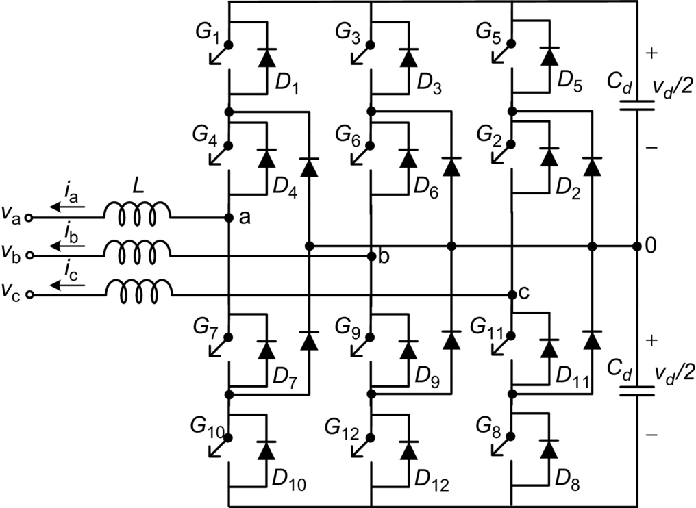
The development of high-power self-commutated devices has led to the development of high-power voltage source converters (VSC), such as the six-pulse two-level VSC shown in Fig. 28.21A [4] or the three-level neutral point clamped VSC shown in Fig. 28.21B [18]. In the figures, the generic switches could be IGBTs, IGCTs, or other self-commutating switches or even the recently developed SiC switches, with an antiparallel connected diode. This set of self-commutated switch and antiparallel diode operates with a unidirectional voltage-blocking capability and a bidirectional current flow. In contrast, the current source converters (CSC) used in HVDC transmission systems use switches (thyristors) operating with unidirectional current flow and bidirectional voltage-blocking capabilities.

In a conventional VSC, for industrial applications, a voltage source is connected at the converter dc side. However, in the case that only reactive power has to be controlled, the dc voltage source may be replaced by a capacitor. If active power has to be absorbed or generated by the compensator, an energy storage system has to be connected at the dc side of the VSC.
In practical applications, small reactors (L) are necessary to connect the VSC to the ac network. This is necessary to avoid current peaks during switching transients. In most cases, these reactors are the leakage inductance of the coupling transformers.
28.4.2.1 Static Synchronous Compensator (STATCOM)
The first high-rating STATCOM started operation in 1991 [19] in Japan and uses three single-phase VSCs to form one three-phase, six-pulse, 10 MVA converter. To guarantee low losses, the switching frequency is equal to the line frequency, and a total of eight sets of three-phase converters are used to form a 48-pulse converter. All the converters have a common dc capacitor in their dc side. In the ac side, the converters are connected in series through a zigzag transformer to eliminate low-frequency voltage harmonics. The device with compensation capability of 80 MVA was developed to increase the transient stability margin of the system, and it has allowed a 20% increase of the transmitted power above the previous stability limit. Since it was developed for improving transient stability margin, it normally operates in standby mode without reactive compensation and, consequently, low losses. During transient situation, this STATCOM operates for a short time until the system is stable.
The development of the first high-power (±100 Mvar) STATCOM in the United States was reported in Ref. [20]. It is based on eight sets of three-phase bridge converters, similar to that shown in Fig. 28.21A; it was developed for reactive power control, so it can operate continuously with acceptable losses. The switching frequency is equal to line frequency, and the number of pulses is 48; therefore, the output voltage waveform is almost sinusoidal, and harmonic filters are not used in both cases referred in Refs. [19,20].
Basic switching control techniques
In FACTS applications, the power ratings of the converters are in the range of some MW to hundreds of MW, and the switching frequency is lower than the switching frequency used in industrial application converters to avoid excessive switching losses. However, there are various switching control types. The most known so far are as follows:
• Multipulse converters switched at line frequency, as in Refs. [19,20]
• Pulse-width modulation (PWM) with harmonic elimination technique [21]
• Sinusoidal PWM [7]
• Cascade converters [22], including the multilevel modular converter (MMC) [23]
Multipulse converters switched at line frequency
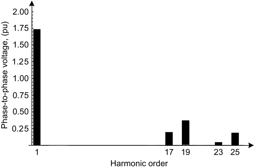
The multipulse converter was the first choice for STATCOM application because it presents low losses and low harmonic content [19,20]. Fig. 28.22 shows a 24-pulse converter based on three-phase, two-level six-pulse converters. In this case, the zigzag transformers are connected in such a way as to produce phase differences of 15, 30, 45, and 60 degrees. With this arrangement, the resulting output voltage and its harmonic spectrum are as shown in Fig. 28.23. The first two harmonic components are the twenty-third- and twenty-fifth-order harmonics. Fig. 28.24 shows the voltage waveform for a 48-pulse converter and its respective harmonic spectrum. In this case, the first two harmonic components are the forty-seventh- and forty-ninth-order harmonics. The total harmonic distortions (THD) for the 24-pulse and 48-pulse converters are 7% and 3.3%, respectively. These converters can also be built by using three-level converters. However, one drawback of the multipulse converter is the complexity, weight, and cost of the transformers, which have to operate with high harmonic content in their voltage and various different turns ratio.


PWM with harmonic elimination technique
One way to avoid the complexity of the multipulse converters is to use PWM with harmonic elimination technique [21]. With this approach, it is possible to use relatively low switching frequency and, consequently, have low switching losses. The PWM modulation is obtained by off-line calculation of the switches at “on” and “off” instants in order to eliminate the low-frequency harmonics. Fig. 28.25A shows an example of voltage waveform with “on” and “off” instants calculated in such a way as to eliminate the fifth-, seventh-, eleventh-, and thirteenth-order harmonics. This voltage corresponds to the voltage between one phase of the converter and the negative terminal of the dc side. Fig. 28.25B shows the control angle as a function of the modulation index ma. Fig. 28.26 shows the harmonic spectrum for the phase-to-phase voltage waveform corresponding to that shown in Fig. 28.25A. Here, it is considered that the rms value of the fundamental component of the voltage in Fig. 28.25 is equal to unity. In Fig. 28.26, the magnitude of the fundamental component is equal to ![]() pu. The higher-order harmonics in the voltage waveform can be eliminated by a relatively small passive filter, so the voltage and the current at the converter terminals are practically harmonic-free; therefore, the transformer that connects a PWM-controlled STATCOM to the grid may be a conventional transformer designed for sinusoidal operation.
pu. The higher-order harmonics in the voltage waveform can be eliminated by a relatively small passive filter, so the voltage and the current at the converter terminals are practically harmonic-free; therefore, the transformer that connects a PWM-controlled STATCOM to the grid may be a conventional transformer designed for sinusoidal operation.

Sinusoidal PWM
The sinusoidal PWM control technique is possibly the simplest to implement and can be synthesized by comparing a sinusoidal reference voltage with a triangular carrier [4]. This switching control method needs a relatively high switching frequency, which is in the range of 1–2 kHz and consequently produces higher switching losses than multipulse STATCOM. The harmonic content at low frequencies is negligible; however, there is a relatively high harmonic content at the switching frequency, which is eliminated by a passive filter.
Cascade converter
The basic cascade converter [22] topology is shown in Fig. 28.27. Only two single-phase full-bridge converters are shown, the first and the nth. However, in actual application, several of them are connected in series and switched at line frequency. The resulting voltage waveform can be similar to the multipulse converter waveform with the advantage that there is no need of transformers to sum up the converter output voltage. Due to the line frequency switching, the switching losses are very low. The resulting voltage waveform can be almost sinusoidal depending on the number of series converters, and the transformer used to connect them to the grid can be a conventional sinusoidal waveform transformer, if necessary. The need to have one dc capacitor for each single-phase converter has two consequences: the number of capacitors is equal to the number of single-phase converters, and the capacitance of each capacitor has to be much higher than three-phase converters. This is because the instantaneous power in each single-phase converter has a large oscillating component at double of the line frequency, and it would force a large voltage ripple in the capacitors if they were small.

Multilevel modular converter
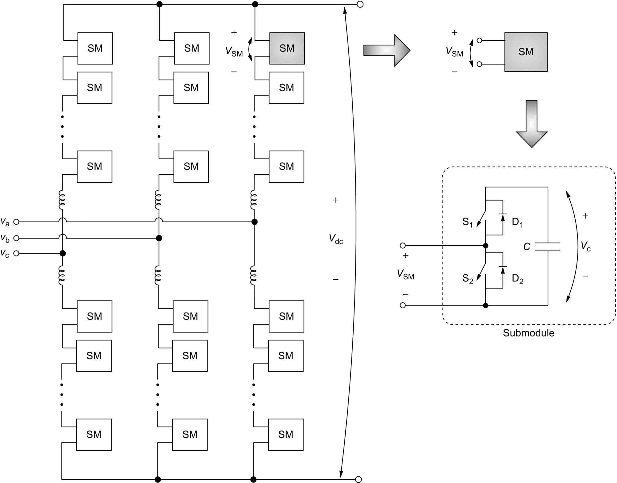
The MMC is an emerging topology for high-power and high-voltage VSC application [23]; it is suitable for either HVDC transmission or FACTS applications [24,25]. For very high-power applications, an MMC is also an alternative, and potentially preferable, to a multilevel converter [26]. The MMC is being presented as the preferred potential candidate for VSC-HVDC system applications [27]. Features like modularity and capability of a multimodule VSC to handle high power or high voltage indicate that a MMC may also be an option to high-power STATCOM and other FACTS compensator such as SSSC, UPFC, or IPFC.
Fig. 28.28 shows the basic topology of a three-phase MMC. Each leg is comprised of n submodules, which are composed of two self-commutated switches and a storage capacitor. Depending on the application, a full-bridge submodule might be necessary instead of the half bridge shown in this figure. A semi-full-bridge submodule topology is an alternative option for blocking short-circuit current in the dc link of the converter [28]. The submodule can be seen as a voltage source with two possible stages 0 or VC where VC is the voltage over the submodule capacitor. Thus, each arm can be understood as a controllable voltage with n possible voltage steps, and the higher the number of submodules, the more approximated sine waveform can be achieved at the ac side. The main advantages of the MMC are low switching losses, low dv/dt over individual switch, modularity, reconfigurable design, and increased energy storage [26]. Beyond that, the MMC can also be directly connected to the power system, that is, without any power transformer [29], which can reduce the overall substation footprint and cost, resulting in a compact-area HVDC substation.
STATCOM control techniques
The control of reactive power in the STATCOM is done by controlling its terminal voltage. Fig. 28.29 shows a simplified circuit in which the ac grid is represented by a voltage source VS behind an impedance jXL and the STATCOM is represented by its fundamental voltage component VI. Fig. 28.30A shows the case when the ac grid phasor voltage VS is in phase with the STATCOM voltage VI and both have the same magnitude. In this case, the line current IL is zero. Fig. 28.30B shows the case when VS is little larger than VI. In this case, the line current IL, which lags the impedance voltage VL by 90 degrees, is also lagging the ac grid phasor voltage VS, and therefore, the STATCOM produces an inductive reactive power. On the other hand, Fig. 28.30C shows the case when VS is little smaller than VI. Hence, the line current IL, which lags the voltage VL by 90 degrees, leads the voltage VS, and therefore, the STATCOM produces a capacitive reactive power. In summary, the STATCOM reactive power can be controlled if the magnitude of its VI voltage is controlled, assuming that it is in phase with VS:
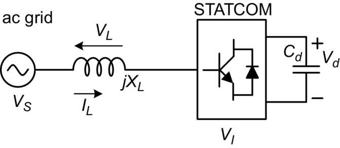

• If |VS| is equal to |VI|, there is no reactive power and no active power in the STATCOM.
• If |VS| is larger than |VI|, the STATCOM reactive power is inductive.
• If |VS| is smaller than |VI|, the STATCOM reactive power is capacitive.
Therefore, the reactive power control in a STATCOM is a problem of how to control the magnitude of its voltage VI. There are two basic principles: (i) in the case of multipulse converters, the output voltage magnitude can only be controlled by controlling the dc-side voltage that is the dc capacitor voltage, and (ii) in the case of PWM control, the dc capacitor voltage can be kept constant, and the voltage can be controlled by PWM controller.
Fig. 28.31A shows the phasor diagram for the case when a phase difference δ between VS and VI is positive. The resulting line current is in such a way that produces an active power flowing into the converter, charging the dc capacitor. Fig. 28.31B shows the phasor diagram for a negative phase angle δ. In this case, the dc capacitor is discharged. Therefore, by controlling the phase angle δ, it is possible to control the dc capacitor voltage.
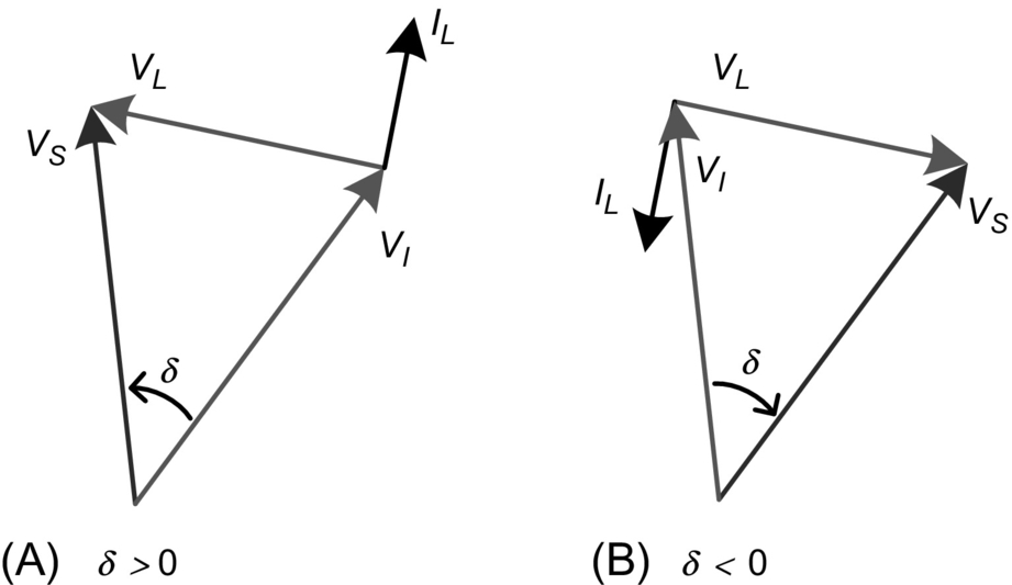
In general, STATCOM based on multipulse converter without PWM has to control its voltage by charging or discharging the dc capacitor, and this voltage has to be variable. On the other hand, STATCOM based on a PWM-controlled converter has to control dc-side capacitor voltage only to maintain it constant. In both cases, the principle shown in Fig. 28.31 is valid.
The STATCOM control technique presented previously illustrates the basic scalar control concepts. However, this compensator can be also controlled by a vector technique [30].
Fig. 28.32 shows a basic control structure for the STATCOM. In this diagram, the vector control technique is implemented in dq synchronous reference frame. This technique is called voltage-oriented control (VOC), in which the grid voltage vector is aligned with the d-axis through the phase-locked loop (PLL) block. This means that the q-axis component of the grid voltage, in steady state, is zero.

The dc-link and grid voltages are controlled through the d- and q-axes, respectively. For the dc voltage control, the voltage across the capacitor is sensed by Hall effect sensor and compared with its reference value. For the grid voltage control, the voltage at the PCC is sensed by Hall effect sensor too, and these signals are transformed to dq components in synchronous reference frame. The next step is to compute the aggregate value for this quantity. The aggregate value is an instantaneous quantity, and it results from the square root of the sum of the squared instantaneous values of currents or voltages. This means that the aggregate value is a constant if and only if the voltages (or currents) in all phases are perfectly sinusoidal and balanced [31,32]. The LPF block is a low-pass filter to eliminate any oscillating components in the signal of the aggregate value. Error signals are generated and are input in proportional-integral (PI) controllers, for both cases, as shown in Fig. 28.32, and the current references are generated. From these, reference currents are in dq synchronous reference frame. In the inner control loop, the current references are compared with measured values of these same variables. Thus, error signals resulting from this operation excite PI controllers that generate voltage references in the controllers’ outputs. Nevertheless, these values must be compensated to avoid coupling between d- and q-axes [33–35].
Another detail, for this diagram, is that there is an intermediate transformation block from abc to αβ instead of the direct transformation abc-dq, because dc values can be present in αβ component signals caused by the acquisition and/or signal conditioning systems or even by the modulation system, in some cases. Thus, they can be eliminated through the installation of high-pass filters (not present in the figure) just after those intermediate blocks, which would not be possible in the case of direct transformation from abc to dq.
Another way to control the STATCOM is by using the instantaneous power theory [36,37], where only the imaginary power is controlled.
STATCOM DC side capacitor
Theoretically, the dc-side capacitor of a STATCOM based on three-phase converters operating in a balanced system and controlling only the reactive power could have a capacitance equal to zero farad, once the three-phase instantaneous reactive power does not contribute to the energy transfer between the dc and ac side [38]. However, in actual STATCOM, a finite capacitor has to be used with the objective of keeping constant or controlled dc voltage as it tends to vary due to the converter switching. One parameter commonly used in synchronous machine is the inertia constant H defined by
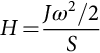
where J and ω are the rotor moment of inertia and angular speed and S is the machine apparent power. A similar parameter for the STATCOM, HST, can be defined by
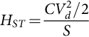
where C and Vd are the dc capacitance and its voltage, respectively, and S is the STATCOM apparent power.
In both cases, the constants H and HST are values in time units corresponding to the relation of the amount of energy stored in the rotor inertia, or in the capacitor, and the machine, or STATCOM, apparent power, respectively. In the case of synchronous machines, the value of H is in the range of few seconds (generally, in the range of 1–3 s), and in the case of the STATCOM, HST value is in the range of milliseconds or below (0.5–50 ms) if only reactive power is to be controlled. These numbers show that the STATCOM based on three-phase converters and designed only for reactive power control (which is the general case) has almost no stored energy in its dc capacitor. On the other hand, STATCOM based on single-phase converters without a common dc link may have larger capacitors as in the case of cascade converters due to the power oscillations at double of the line frequency.
There are STATCOM (in some cases with different names) that are designed for operation with unbalanced loads. In this case, the dc capacitor has to be also much larger than in the case of balanced systems to avoid large voltage ripple on the dc voltage due to power oscillations at twice the line frequency, which appears naturally in unbalanced systems [33,39] or unbalanced voltages [34] or system with flicker problem [35,40]. In this case, the STATCOM compensates reactive power and the instantaneous oscillating active power due to the negative sequence current components. In fact, this is an extension of the shunt active power filter application where the goal is the current harmonic compensation, which includes negative sequence currents even at the fundamental frequency. If subharmonics are present, the device is able to filter them out as well.
STATCOM with energy storage
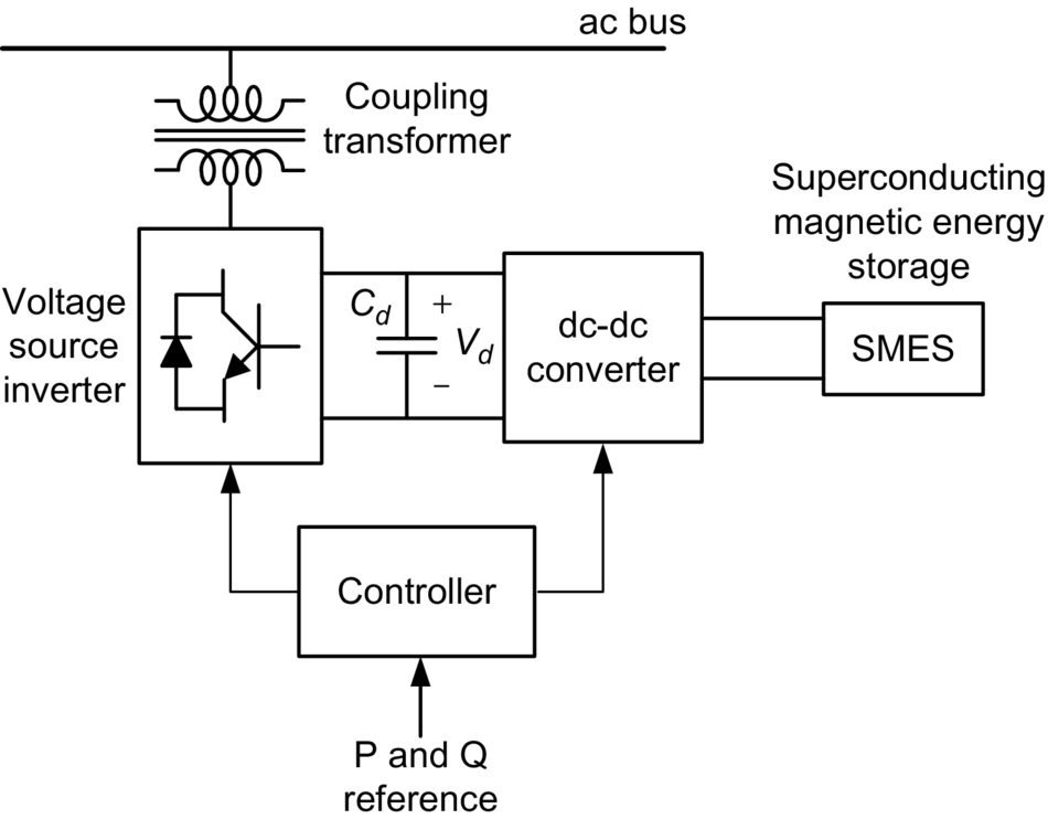
In general, the STATCOM is designed for reactive power compensation, and it does not need large energy storage elements. However, there are some applications where it may be interesting to have some energy stored in the dc side, for example, to compensate for active power for a short time. In these applications, the dc-side capacitor has to be substituted by a voltage source energy storage device like a battery [41] or a double-layer capacitor (super capacitor). Another possibility is to store energy in superconducting magnetic energy storage (SMES) systems [42,43]. A natural solution for the use of the superconducting reactor would be the connection to the ac grid through a current source converter (CSC) instead of the voltage source converter. However, this has not been the case found in the literature. Fig. 28.33 shows a block diagram of a typical STATCOM/SMES system, where the SMES is connected to the dc side of the STATCOM through a dc-dc converter, which converts the direct current in the superconductor magnet to dc voltage in the STATCOM dc side and vice versa. This STATCOM can control reactive power continuously and active power for a short time, normally up to few seconds, depending on the amount of energy stored in the superconducting magnet.
Comparison between SVC and STATCOM
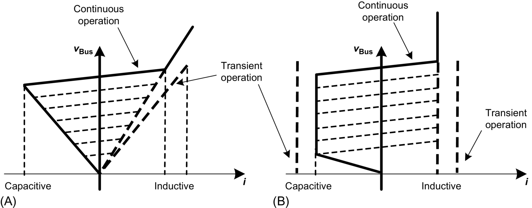
Fig. 28.34A shows the steady-state volt-ampere characteristics for the SVC shown in Fig. 28.14, whereas Fig. 28.34B shows the same characteristics for a STATCOM. For operation at rated voltage, both devices can present similar characteristics in terms of control range. However, current compensation capability of SVC for lower voltages becomes smaller, whereas in the STATCOM, it does not change significantly for voltages lower than rated value (but approximately above 0.2 pu). This is explained by the fact that the SVC is based on impedance control, whereas the STATCOM is based on current controlled voltage source control. Therefore, in the SVC, the current decreases with a corresponding voltage decrease, whereas in the STATCOM, the current capability of the converters depends only on the switching device used, so the maximum current can be kept unchanged even for a low voltage condition. This is an important characteristic, especially in applications where the voltage may drop (as in most cases), where the STATCOM presents a better performance.
28.4.2.2 Adjustable Speed Synchronous Condenser (ASSC)
The adjustable speed synchronous condenser is not exactly a FACTS compensator, as it contains an electric machine. However, it may be an interesting shunt device to compensate reactive power continuously and relatively large amounts of active power for a short time. The basic topology of this compensator is shown in Fig. 28.35. It is based on a double-fed machine with a conventional three-phase winding in the stator and a three-phase winding in the rotor. The latter is supplied by a three-phase converter connected back-to-back to a second converter, which is connected to the grid.
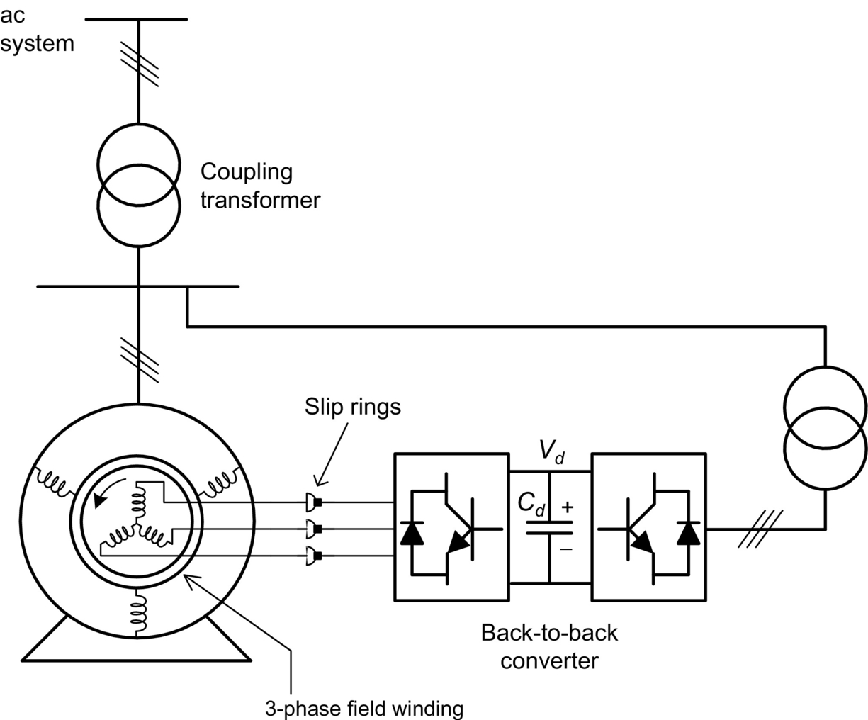
This configuration allows the generation of a rotating magnetic flux in the rotor, which depends on the rotor converter frequency. When the machine is rotating at synchronous speed, the rotor converter operates at zero frequency and the magnetic flux in the rotor is stationary with respect to the rotor itself. In this case, the compensator operates as a conventional synchronous condenser.
However, when the rotor speed is lower or higher than the synchronous speed (normally during transients), the rotor converter generates a field current with the necessary frequency to keep the stator and rotor fluxes synchronized—if the synchronous frequency is 60 Hz and the rotor is running, for instance, at 58 Hz, the rotor converter has to supply voltage or current at 2 Hz so as to synchronize the fluxes. Naturally, it would be more interesting to use field-oriented control [44] instead of scalar control to get a better performance.
This hybrid compensator may supply energy to the ac system, if rotor speed is decreased. This machine is designed to have relatively large rotor inertia so as to present a large inertia constant (which may be in the range of more than 10 s). It is also called adjustable speed rotary condenser [45]. Operation at speeds higher than the synchronous speed is also possible, if it is necessary to absorb energy from the grid.
One of the advantages of this device is that a compensator with power in the range of 400 MVA may be synthesized with power electronics converter rated at a small fraction of this power and with a large capability to supply both active (for a few seconds) and reactive power (continuously) [45].
28.4.2.3 Static Synchronous Series Compensator
In contrast to the STATCOM, which is a shunt FACTS compensator, it is possible to build a converter-based compensator for series compensation. Fig. 28.36 shows the basic diagram of a static synchronous series compensator (SSSC) based on voltage source converter (VSC) with a capacitor in its dc side and connected in series with the transmission line through a transformer [46]. The inputs to the SSSC controller shown in this figure are the line current and voltage and the active and reactive power references pSE⁎ and qSE⁎, respectively. In general, only reactive power is compensated, and in this case, the active power reference pSE⁎ is zero and qSE⁎ is chosen so as to control power flow. Naturally, in the case of power flow control, it is necessary to have another control loop for this purpose and this is not shown in the figure.
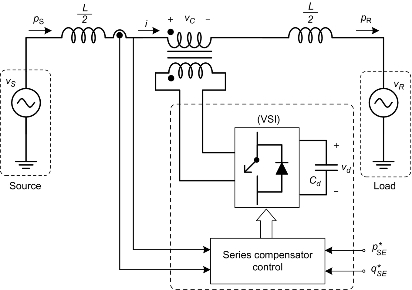
One should note that if current is flowing in the transmission line, the SSSC controls reactive power by generating voltage vC in quadrature with the line current. The device then shows capacitive or inductive equivalent impedance by increasing or decreasing the power flow, respectively. The compensation characteristic is as shown in Fig. 28.8, for the case of series compensation where the transmitted power is always positive for ![]() . That is, with reactive power control, it is only possible to transmit in one direction. However, if instead of controlling qSE⁎, voltage vC is controlled, it is possible to have power flow reversion. Fig. 28.37 shows the power flow characteristics of a transmission line with an SSSC using constant voltage control. The voltage is in quadrature with the current, and its magnitude is kept constant. The figure shows that it is possible to have power flow reversion for small values of δ with a constant compensation voltage vC.
. That is, with reactive power control, it is only possible to transmit in one direction. However, if instead of controlling qSE⁎, voltage vC is controlled, it is possible to have power flow reversion. Fig. 28.37 shows the power flow characteristics of a transmission line with an SSSC using constant voltage control. The voltage is in quadrature with the current, and its magnitude is kept constant. The figure shows that it is possible to have power flow reversion for small values of δ with a constant compensation voltage vC.

It should be noted that the discussion presented with respect to the converters topologies and controllers for the case of the STATCOM is also valid for the case of the SSSC. The SSSC can be used for power flow control and for power oscillation damping as well.
28.4.2.4 Gate-Controlled Series Capacitor
Fig. 28.16 shows the TCSC, which is basically a TCR in parallel with a capacitor and both connected in series with a transmission line. The combination is effective in continuously controlling the equivalent capacitive reactance presented to the system, mainly for power flow control and power oscillation damping purposes. It was also pointed out that the device has the disadvantage of a resonant condition due to the parallel association of capacitor and TCR (see Fig. 28.18).
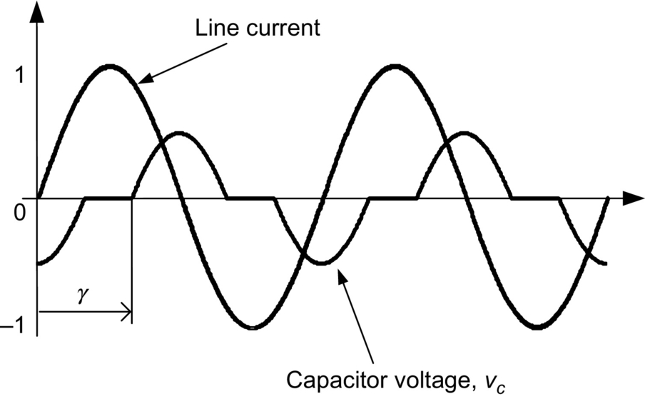
In [47], the continuously regulated series capacitor using GTO thyristors to directly control capacitor voltage is presented. Fig. 28.38 shows this new device that is called gate-controlled series capacitor (GCSC) [48], hereafter renamed as the gate-controlled series capacitor (GCSC) because it may also be built using other self-commutated switches such as IGBTs or IGCTs.

The GCSC circuit consists of a capacitor and a pair of self-commutated switches in antiparallel connection. As the switches operate under ac voltage, they must be able to block both direct and reverse voltages and allow current control in both directions.
Fig. 28.39 shows the voltage and current waveforms for the GCSC, where the current in the transmission line is assumed to be sinusoidal. If the switches are kept turned on, the capacitor is bypassed and does not present any compensation effect. If they are kept off, the capacitor is fully inserted in the line. On the other hand, if the switches are conducting and are turned off at a given blocking angle γ counted from the zero crossings of the line current, the capacitor voltage vC appears as a result of the integration of the line current passing through it. The next time the capacitor voltage crosses zero, the switches are turned on again, to be turned off at the next turn-off angle γ. With this switching control sequence, it must be clear that the switches always switch at zero voltage. This is an interesting feature for the series connection of the switches under high-voltage operation [49].
The GCSC has some advantages when compared with the TCSC—the blocking angle can be continuously varied, which in turn varies the fundamental component of the voltage vC. Also, it can be smaller than the TCSC [50]. Moreover, the dynamic response of the GCSC is generally better than that of the TCSC [51].
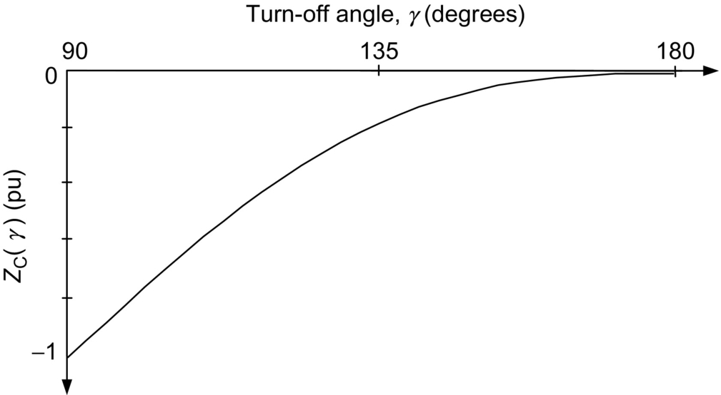
The impedance of the GCSC at the fundamental frequency, as a function of the blocking angle γ, is shown in Fig. 28.40. A blocking angle of 90 degrees means the capacitor is fully inserted in the circuit, whereas a value of 180 degrees corresponds to a situation where the capacitor is bypassed and no compensation occurs.
28.4.2.5 Unified Power Flow Controller
The unified power flow controller (UPFC) is a more complete transmission line compensator [52], shown as a simplified block diagram in Fig. 28.41. This device can be understood as a STATCOM and an SSSC with a common dc link. The energy storing capacity of the DC capacitor is generally small, and so the shunt converter has to drain (or inject) active power from the grid in exactly the same amount as the active power being injected (or drained) by the series converter. If this is not followed, the dc-link voltage may increase or decrease with respect to the rated voltage, depending on the net power being absorbed or delivered by both converters. On the other hand, the reactive power in the shunt or series converter can be controlled independently, giving a great flexibility to the power flow control.
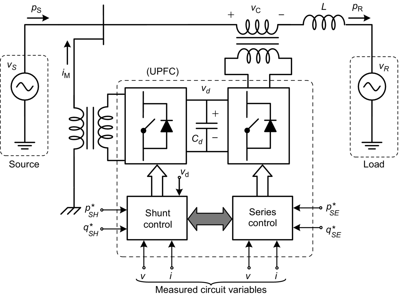
The phasor diagram in Fig. 28.42 shows that the UPFC can be controlled in such a way as to produce any voltage phasor in series with the transmission line that fits inside the dashed-line circle on top of the phase voltage phasors. The maximum radius of the circle is limited by the voltage limitation of the series converter. The fact that the locus of vc is a circle is one of the greatest advantages of the UPFC when compared with the thyristor-based phase shifter. If the UPFC presents capacitive or inductive reactive power in parallel with the system, the magnitude of voltage VS is increased or decreased, respectively. This extra characteristic increases the locus of the series voltage vc. Of course, this effect is only possible if an inductive impedance is present in series with the voltage source VS, which is normally the case.

The shunt compensator of the UPFC is normally used with two objectives. The first is to control the reactive power in the point of connection, therefore controlling the voltage at this point. The second is to control active power in such a way as to control the dc-link voltage. The control technique to be used can be similar to the one used in STATCOM. The series compensator can be controlled in the same way as the SSSC, with the difference that in this case, it may control active and reactive power. Naturally, the active power control in the series compensator would change the capacitor voltage that should be controlled by the shunt compensator.
The UPFC can also be used to regulate directly the voltage in distribution feeder or transmission line. In the case that the UPFC is based on single-phase converter units (UPFC-1ɸ) [53,54], it can control unbalanced voltage. This application is named as direct voltage control (DVC) [55], and it is a promising solution for power quality issues in distribution grid with high penetration of intermittent generation sources, such as wind or solar power. Since this grid has a resistive characteristic, the indirect voltage control, based on shunt reactive compensator, could be ineffective [56]. Moreover, the use of single-phase converters permits the direct voltage control even under unbalanced operation, and each phase voltage can be controlled independently to balance the grid voltage.
Fig. 28.43 shows the basic line diagram of the UPFC based on single-phase back-to-back VSC unit for phase a. In each phase, one converter (VSC 1a) is shunt connected to the grid through a transformer (Tsh), and the other converter (VSC 2a) is directly connected in series at the point that voltage should be controlled (PCC). In Fig. 28.43, each VSC is connected in series with the secondary windings of the grid transformer (Tgrid), avoiding a coupling transformer. The series converter of each UPFC 1ϕ is controlled to synthesize a compensation voltage (Vcomp) to keep the PCC voltage regulated at a reference value, that is,

where ![]() (j=a, b, c) is the phasor of voltage phase “j” in secondary wind of the transformer and
(j=a, b, c) is the phasor of voltage phase “j” in secondary wind of the transformer and ![]() is the phasor of the compensation voltage synthetized by the series VSC connected to phase “j.” The compensation voltage can be represented as
is the phasor of the compensation voltage synthetized by the series VSC connected to phase “j.” The compensation voltage can be represented as
where ![]() is the complex compensation factor, which means that both the magnitude and the phase of the compensation voltage can be controlled independently in each phase. This feature is suitable for grids with unbalanced voltage issues. If only the magnitude of the voltage in each phase should be compensated, the compensation factor is a real number, which means that the compensation voltage,
is the complex compensation factor, which means that both the magnitude and the phase of the compensation voltage can be controlled independently in each phase. This feature is suitable for grids with unbalanced voltage issues. If only the magnitude of the voltage in each phase should be compensated, the compensation factor is a real number, which means that the compensation voltage, ![]() , is in phase to the secondary phase voltage of the grid transformer,
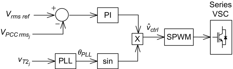
, is in phase to the secondary phase voltage of the grid transformer, ![]() , and a simple control strategy can be applied as shown in Fig. 28.44. This figure shows the control block diagram of the series VSC for direct voltage magnitude compensation for one phase. The rms value of the PCC phase voltage (
, and a simple control strategy can be applied as shown in Fig. 28.44. This figure shows the control block diagram of the series VSC for direct voltage magnitude compensation for one phase. The rms value of the PCC phase voltage (![]() ) is compared with the reference value (Vrms ref); the output error is processed by a PI controller, generating the compensation voltage magnitude. This signal is multiplied by a sinusoidal signal, sin(θPLL), in phase with secondary phase voltage of the grid transformer,
) is compared with the reference value (Vrms ref); the output error is processed by a PI controller, generating the compensation voltage magnitude. This signal is multiplied by a sinusoidal signal, sin(θPLL), in phase with secondary phase voltage of the grid transformer, ![]() , obtained from the synchronizing circuit (phase locked loop (PLL)).
, obtained from the synchronizing circuit (phase locked loop (PLL)).
28.4.2.6 Interline Power Flow Controller
The interline power flow controller (IPFC) [53] is a UPFC-derived device with the objective of controlling power flow between two lines instead of one line as in the UPFC. Fig. 28.45 shows a basic block diagram of an IPFC with two converters to control the power flow in lines 1 and 2. The minimum number of converters connected back-to-back is two, but there may be more. Each converter should be connected in series with a different transmission line and should control power flow in this line with the following conditions:

• The reactive power control can be totally independent in each converter.
• The active power flowing into or out of each converter has to be coordinated in such a way that the dc-link voltage is kept controlled.
The dc-link voltage control can be achieved in a similar way as in the case of the UPFC. In this case, one of the series converters can control the compensation voltage freely, and it may produce active power flowing into or from the dc link, which would charge or discharge the dc-link capacitor. Therefore, the other converter has to be controlled to regulate this dc voltage. If there are n converters with n greater than two, (![]() ) converters can absorb or generate active power, whereas one converter has to control the dc-link voltage. Anyway, all n converters can control reactive power freely. For instance, this concept allows the control of the power flow in n lines, and it is possible to transfer active power from one line to another to balance power flow in n parallel transmission lines.
) converters can absorb or generate active power, whereas one converter has to control the dc-link voltage. Anyway, all n converters can control reactive power freely. For instance, this concept allows the control of the power flow in n lines, and it is possible to transfer active power from one line to another to balance power flow in n parallel transmission lines.
28.4.2.7 Convertible Static Converter
Following the IPFC, a more generic concept is the convertible static converter (CSC) [57,58], which is based on the connection of a voltage source converter in various different topologies. Considering one simple case of two transmission lines and two converters with apparent power each equals to S, it is possible to have the following topologies:
• Two converters connected in shunt operating as a STATCOM rated at 2S apparent power
• Two converters connected in series with one transmission line forming an SSSC with 2S apparent power
• One converter connected in shunt and the other in series forming a UPFC
• One converter connected in series with one line and the other connected in series with the other line forming an IPFC
Other topologies are possible depending on how the converters are connected in the system. The basic control of each converter depends on how it is being used if, as a STATCOM, SSSC, UPFC, or IPFC.
28.5 Ancillary Services
Ancillary services are essential for grid reliability, including these services that can facilitate wind farms obtaining connection permits in some countries. Thus, taking advantage of the current scenario with high penetration of wind turbines in the distribution and transmission systems in several regions throughout the world, more and more, these services are being incorporated into the modern wind farms. These services include voltage and reactive power support, frequency-active power control, and fault ride through capability. This is all possible thanks to the ability of modern wind turbines to make use of FACTS controller features. Nowadays, most of wind farms are based on doubly fed induction generator (DFIG) or permanent magnet synchronous generator (PMSG). However, solar photovoltaic power plants can also contribute to these services, since they are connected to the grid via power inverters [59]. So, photovoltaic and wind turbine power plants can contribute to increase the reliability of distribution and transmission systems, as indicated in Fig. 28.46.

Modern grid codes define a range of technical requirements that generation power plants must fulfill. For example, it is very common in the voltage support through reactive current injection during fault operation and the voltage support of the power system in normal operation through the reactive power control. Advanced control designs associated with power electronics converters are responsible to provide these ancillary services [59,60].
Wind turbines connected to the grid through a static power converter can provide an adequate inertial response to the system. The idea behind that is that the converter control system ensures a resistant torque to the wind turbine shaft during a frequency disturbance to extract energy. Thus, the behavior of synchronous generator with large inertia can be emulated [61–65].
Generally, a photovoltaic power plant has no energy storage; therefore, it cannot emulate an inertia, so it cannot contribute by itself to increasing the inertia of the system. Unless it uses other components like a flywheel or a battery to allow this service [61].