14.7 Applications of AC-AC Converters
14.7.1 Applications of AC Voltage Controllers
AC voltage controllers are used either for control of the rms value of voltage or current in lighting control, domestic and industrial heating, speed control of fan, pump or hoist drives, soft starting of induction motors, etc. or as static ac switches (on/off control) in transformer tap changing, temperature control, speed stabilization of high-inertia induction motor drives like centrifuge, capacitor switching in static reactive power compensation, etc.
In fan or pump drives with induction motors, the torque varies as the square of the speed. So, the speed control is required in a narrow range, and an ac voltage controller is suitable for an induction motor with a full load slip of 0.1–0.2 in such applications. For these drives, braking or reverse operations are not needed, but for the crane hoist drive, both motoring and braking are needed, and a four-quadrant ac voltage controller can be obtained by a modification of the ac voltage controller circuit as shown in Fig. 14.44. SCR pairs A, B, and C provide operation in quadrants I and IV and A, B, and C in quadrants II and III. While changing from one set of SCR pairs to another, care should be taken to ensure that the incoming pair is activated only after the outgoing pair is fully turned off.

Ac voltage controllers are being increasingly used for soft starting of induction motors, as they have a number of advantages over the conventional starters such as smooth acceleration and deceleration, ease in implementation of current control, simple protection against single-phasing or unbalanced operation, reduced maintenance and losses, and the absence of current inrush. Even for the fixed-speed industrial applications, the voltage controllers can be used to provide a reduced stator voltage to an induction motor to improve its efficiency at light load and result in energy saving. Operation at an optimum voltage reduces the motor flux which, in turn, reduces the core loss and the magnetizing component of the stator copper loss. Considerable savings in energy can be obtained in applications where a motor operates at no load for a significant time such as in drills, machine tools, woodworking machines, and reciprocating air compressors. A popular approach to find an optimum operating voltage is to maximize the motor power factor by maintaining a minimum phase shift between the voltage and current after sensing them.
The ac switch with on/off control used in driving a high-inertia centrifuge involves switching on of the motor when the speed of the centrifuge drops below the minimum allowable level and switching off when the speed reaches the maximum allowable level—thus maintaining a constant average speed. An identical scheme of control is used with an ac switch for temperature control of an electric heater or air conditioner.
Integral cycle control is well suited to heating control while it may cause flicker in normal incandescent lighting control and speed fluctuations in motor control. However, with this control, less voltage distortion is produced in the ac supply system, and less radio-frequency interference is propagated when compared with the phase-controlled system.
14.7.2 Applications of Cycloconverters
Cycloconverters as frequency changers essentially find well-established applications in (1) high-power low-speed reversible ac motor drives with constant-frequency input and (2) constant-frequency power supplies with a variable-frequency input as in variable-speed constant frequency (VSCF) system, whereas they find potential applications in (3) controllable volt-ampere reactive (VAR) generators for power factor correction, and (4) ac system interties linking two independent power systems as demonstrated in [15].
Variable Speed AC Drives. In this category, the applications of cycloconverter-controlled induction motor and synchronous motor drives have been adequately reviewed in [9]. Cycloconverter-fed synchronous motors are well suited for low-speed drives with high torque at standstill, and high-capacity gear-less cement mills (tube or ball mill above 5 MW) have been the first applications of these drives.
Since the 1960s, as developed by Siemens and Brown Boveri, one of the early installations employs a motor rating of 6.4 MW having a rotor diameter of 5 m and length of 18.5 m, whereas the stator construction is similar to that of a hydroelectric generator with 44 poles requiring 5.5 Hz for maximum speed of 15 rpm. The motor is flanged with the mill cylinder without additional bearings or “wrapped” directly around it, known as a ring motor [93]. With the evolution of field orientation or vector control, cycloconverter-fed synchronous motors have replaced or are replacing the dc drives in the reversing rolling mills (2/4 MW) with extreme high-dynamic requirements for torque and speed control [94–96], in mine winders and haulage [96,97] of similar high ratings and in icebreakers and ships equipped with diesel generators with power ratings of about 20 MW/unit [98]. In these applications, the cycloconverter-fed synchronous motor is in self-controlled mode and known as ac commutatorless motor when the cycloconverter firing signals are derived from a rotor shaft position sensor, so that the frequency is slaved to the rotor speed and not vice versa with the result that the hunting and stability problems are eliminated, and the torque is not limited to pullout value. Further, with field control, the motor can be operated at leading power factor when the cycloconverter can operate with load commutation from the motor side at high speed in addition to the line commutation from the supply at low speed, thus providing speed control over a wide range. A cycloconverter-fed ac commutatorless motor is reported in [99] where the cycloconverter is operated both in sinusoidal and trapezoidal mode—the latter is attractive for better system power factor and higher voltage output at the cost of increased harmonic content [1]. A stator-flux-oriented vector control scheme for a six-pulse circulating current-free cycloconverter-fed synchronous motor with a flux observer suitable for a rolling mill drive (300–0–300 rpm) is reported in [12]. A 12-pulse, 9.64 MVA, and 120/33.1 Hz cycloconverter-linear synchronous motor combination for Maglev Vehicle ML-500, a high-speed train, (517 km/h) is in the process of development in Japan since the early 1980s [100]. Several recent projects involving very high-power (larger than 15 MW) semiautogenous grinding (SAG) mills with cycloconverter-fed synchronous motor drives in mining applications in Peru and Brazil are reported in [101]. Latest technological advances, applications, and future trends of cycloconverters in industrial medium-voltage drives have been discussed in [102].
Regarding cycloconverter-fed induction motors, early applications were for control of multiple run-out table motors of a hot strip mill, high-performance servo drives, and controlled slip-frequency drive for diesel electric locomotives. Slip-power-controlled drives in the form of static Scherbius drives with very high ratings using cycloconverter in the rotor of a doubly fed slip ring induction motor have been in operation for high-capacity pumps, compressors [103], and even in a proton-synchrotron accelerator drive in CERN, Geneva [104]. Though synchronous motors have been preferred for very high-capacity low-speed drives because of their high rating, ability to control power factor, and precisely set speed independent of supply voltage and load variations, induction motors, because of their absence of excitation control loop, simple structure, easy maintainability, and quick response, have been installed for cycloconverter-fed drives in Japan. For example, a seamless tube piercing mill [105] where a squirrel cage six-pole 3 MW, 188/300 rpm, 9.6/15.38 Hz, and 2700 V motor is controlled by a cycloconverter bank of capacity 3750 KVA and output voltage 3190 V.
Constant Frequency Power Supplies. Some applications such as aircraft and naval ships need a well-regulated constant-frequency power output from a variable-frequency ac power source. For example, in aircraft power conversion, the alternator connected to the engine operating at a variable speed of 10,000–20,000 rpm provides a variable-frequency output power over 1200–2400 Hz range that can be converted to an accurately regulated fixed frequency output power at 400 Hz through a cycloconverter with a suitable filter placed within a closed loop. The output voltages of the cycloconverter are proportional to the fixed frequency (400 Hz) sine-wave reference voltage generator in the loop.
Both synchronous and induction motors can be used for VSCF generation. The static Scherbius system can be modified (known as Kramer drive) by feeding slip power through a cycloconverter to a shaft-mounted synchronous machine with a separate exciter for VSCF generation. A new application in very high power ratings of constant frequency variable speed motor generators with cycloconverter is in pumped storage schemes using reversible pump turbines for adaptation of the generated power to varying loads or keeping the ac system frequency constant. In 1993, a 400 MW variable speed pumped storage system was commissioned by Hitachi at Okhawachi hydropower plant [106] in Japan where the field windings of a 20-pole generator/motor are excited with three-phase low-frequency ac current via slip rings by a 72 MVA, three-phase 12-pulse line-commuted cycloconverter. The armature terminals rated at 18 kV are connected to a 500 kV utility grid through a step-up transformer. The output frequency of the circulating current-free cycloconverter is controlled within ![]() , and the line frequency is 60 Hz. The variable speed system has a synchronous speed of 360 rpm with a speed range
, and the line frequency is 60 Hz. The variable speed system has a synchronous speed of 360 rpm with a speed range ![]() . The operational system efficiency in the pump mode is improved by 3% when compared with the earlier constant speed system.
. The operational system efficiency in the pump mode is improved by 3% when compared with the earlier constant speed system.
Static VAR Generation. Cycloconverters with a high-frequency (HF) base, either an HF generator or an oscillating LC tank, can be used for reactive power generation and control, replacing synchronous condensers or switched capacitors as demonstrated in [15]. If the cycloconverter is controlled to generate output voltage waves whose wanted components are in phase with the corresponding system voltages, reactive power can be supplied in either direction to the ac system by amplitude control of the cycloconverter output voltages. The cycloconverter will draw leading current from (i.e., it will supply lagging current to) the ac system when its output voltage is greater than that of the system voltage and vice versa.
Interties between AC Power Systems. The naturally commutated cycloconverter (NCC) was originally developed for this application to link a three-phase, 50-Hz ac system with a single-phase ![]() railway supply system in Germany in the 1930s. Applications involve slip-power-controlled motors with subsynchronous and supersynchronous speeds. The stator of the motor is connected to 50-Hz supply, which is connected to the rotor and through a cycloconverter, and the motor drives a single-phase synchronous generator feeding to
railway supply system in Germany in the 1930s. Applications involve slip-power-controlled motors with subsynchronous and supersynchronous speeds. The stator of the motor is connected to 50-Hz supply, which is connected to the rotor and through a cycloconverter, and the motor drives a single-phase synchronous generator feeding to ![]() system [107,108]. A static asynchronous intertie between two different systems of different frequency can be obtained by using two NCCs in tandem, each with its input terminals connected to a common HF base. As long as the base frequency is appropriately higher than that of the either system, two system frequencies can be either same or different. The power factor at either side can be maintained at any desired level [15].
system [107,108]. A static asynchronous intertie between two different systems of different frequency can be obtained by using two NCCs in tandem, each with its input terminals connected to a common HF base. As long as the base frequency is appropriately higher than that of the either system, two system frequencies can be either same or different. The power factor at either side can be maintained at any desired level [15].
14.7.3 Applications of Matrix Converters and New Developments
The practical applications of the matrix converters, as of now, are very limited. The main reasons are (1) nonavailability of the bilateral fully controlled monolithic switches capable of high-frequency operation, (2) complex control law implementation, (3) an intrinsic limitation of the output/input voltage ratio, and (4) commutation and protection of the switches. The switches are assembled from existing discrete devices resulting in increased cost and complexity, and only experimental circuits of conventional matrix converters (CMC) of capacity up to 150 kVA [109] for a single unit have been built. However, with the advances in device technology, it is hoped that the problems will be solved eventually, and the MC will not only replace the NCCs in all the applications mentioned under Section 14.7.2 but also take over from the PWM rectifier-inverters as well. Yaskawa has introduced several drives based on matrix converters, most of which are for industrial purposes. U1000 [110] (Fig 14.45) is an industrial drive available in 200/400 V and power ranging from 5 to 500 hp. Another drive Z1000U [112] is an HVAC drive available between 7.5 and 350 hp. AC7 [111] is yet another smaller version with power range of 7.5–125 hp. AC7 is not commissioned in the Americas. Another interesting applications of multilevel and multicell matrix converters for medium-voltage high-power drives have been developed [113] Super energy-saving multicell medium-voltage matrix converters (FSDrive-MX1S) of rating 3 kV, 200–3000 kVA or 6 kV, and 400–6000 kVA have been built by Yaskawa Electric, Japan [114], where by intelligently phase shifting the carrier of each cell and combining them in the motor windings, medium voltages are achievable as shown in Fig. 14.46. The salient features of these medium-voltage converters are as follows:


• Excellent input current waveform due to multiple phase shifting winding of the input transformer;
• Flexible design, three cells in series yielding 3.3 kV and 200–3000 kVA and six cells in series yielding 6 kV and 400–6000 kVA system;
• Excellent output voltage waveform due to multistep configuration.
The applications for these drives as recommended are as follows: with heavy loads that require regenerative energy such as steel manufacturing process lines or cargo handling machinery, and also that need power regeneration for a long period such as winders for paper Fig. 14.47.
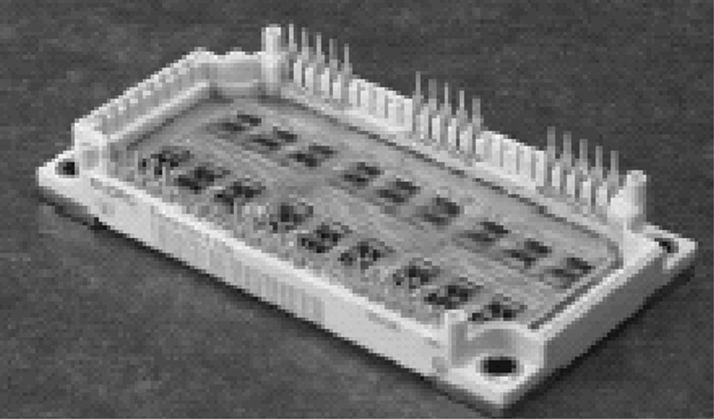
Recently, reverse blocking IGBTs have opened up the possibility of bidirectional switch (BDS) construction for a practical matrix converter with just two back-to-back devices [116–118]. A compact full matrix converter power module EconoMac [115] in a single package using 18 IGBT devices (35 A and 1200 V) and diodes in the common collector configuration (Fig. 14.44) is available with Eupec/Siemens, Germany. This packaging minimizes the stray inductance in the current commutation paths. Fuji and Powerex have developed engineering samples for matrix converter output leg in a module using RB-IGBTs. A new power electronic building block (PEBB) configuration for a low-cost MC has been proposed in [119]. Recently, an efficient approach to design discrete packaging of bidirectional resonant power switch for matrix converters has been proposed by computing the magnetic field orientation inside the switching cell [120]. Several new concepts in protection, commutation, switch design, and modulation strategy have been presented in [121].
Several new methods like overmodulation [122], adaptive rate regulation [123], and two-side modulation control [124] have been introduced with experimental results to achieve higher voltage transfer ratio. A matrix converter-based three-phase open-end winding ac machine drive having matrix converters, one at each side of the open-end winding with space vector PWN has been recently described in [125] to achieve several simultaneous benefits, such as converter voltage gain up to 1.5, controllable grid power factor, and elimination of the high-frequency common-mode voltage at the machine terminals. A generalized scalar PWM (GSPWM) technique to reduce the common-mode voltage in matrix converter without degrading the input currents' quality has been studied in a recent paper [126].
Design and loss comparison of matrix converters and dc link voltage source converters (VSC) have been discussed in [127,128]. It is shown that although MC requires 50% more semiconductors and gate drives excluding clamp circuit, the active silicon area and the number of gate unit power supplies are comparable with that of VSC of the same power rating. The losses of both converter systems are roughly the same at the typical range of 40%–70% of rated torque and speed and a switching frequency of 10 kHz. The MC realizes a distinct better efficiency (92.5%–96%) at 100% torque compared with VSC for the same IGBT modules. Also, the maximum switching frequency of the MC (30 kHz at 250% rated torque) is also substantially higher. The low losses allow a reduction of current ratings (by 33%) of IGBT modules in MC. The extra harmonic losses due to use of a matrix converter for a motor drive with two commonly used modulation techniques have been computed and compared in [129].
Various potential applications of matrix converters have been proposed, and experiments conducted in the field of VSCF systems such as wind turbine and microturbine [130], switched mode power supplies [131], doubly fed induction motor [132,133] including wind power system applications [134], and marine propulsion [135]. Few modern solutions for industrial matrix converter applications including a new integrated matrix converter motor (MCM) have been reported [136,137]. The range of published practical implementations varies from a 2 kW matrix converter using silicon carbide devices and switching at 150 kHz for aerospace applications built at ETH in Zurich, Switzerland, to a 150 kVA converter using 600 A IGBTs built at US army research labs in collaboration with the University of Nottingham, the United Kingdom [54,109]. A matrix converter using MCTs with enhanced commutation times is described in [138].
The complex control schemes of matrix converter demand higher test requirements, and one of the modern means of testing the controllers before final integration on actual apparatus is to make hardware-in-the-loop (HIL) real-time simulation tests as developed recently [139].
Matrix converter-fed adjustable speed drives (ASDs) have the advantages of inherent four-quadrant operation, the absence of bulky dc link electrolytic capacitors, clean input power characteristics with high input power factor, and increased power density with the possibilities of operating at higher temperatures. However, due to the absence of the dc link, these are more susceptible to input power disturbances, and a ride-through module is needed to be added for these drives under short-term power interruption. Such a module as developed with minimal addition of hardware and software into a matrix converter (230 V and 3 kVA) has been reported in [140]. A PWM modulation strategy for fault tolerant operation of the matrix-converter-based drives against opened switch, opened phase faults, and shorted winding failures has been proposed in [141]. This can improve the reliability of the matrix converter drives as it is possible to keep continuous by regulating the two remaining phases after isolating the faulted phase.
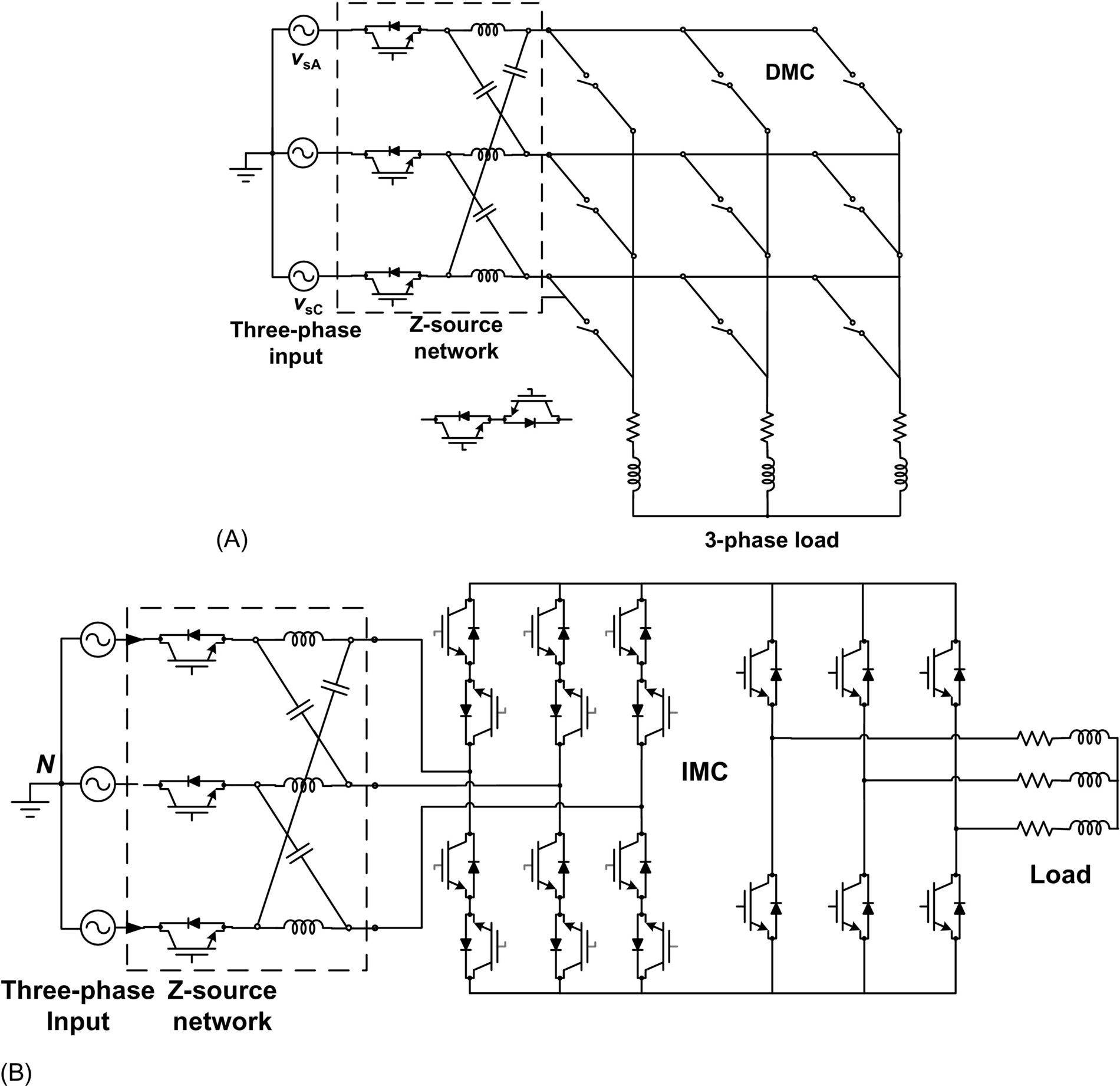
A novel application of a three-phase matrix converter as the static conversion unit for a ground power supply unit for aircraft servicing has been presented in [142] to provide a compact solution with no dc link and the capability to generate a high quality 400-Hz sinusoidal waveform in the steady state. Three-phase Z-source matrix converter is under consideration. The benefit of Z-sourcing is that firstly, a VTR more than 0.866, can be achieved. Ref. [143] discusses a family of Z-sourced DMCs in which a VTR of 0.992 is achieved. Secondly, it helps in overcoming the commutation problem. Work on Z-source IMC is also being done [144]. Comparative study on various Z-source and quasi-Z-source IMC is done in [145]. A detailed evaluation on various Z-source DMCs and IMCs is recently done in [56]. Z-source DMC and IMC are shown in Fig. 14.48. A direct ac-ac current source matrix converter for applications in industrial power systems is introduced in [146]. A dynamic voltage restorer (DVR) system employing matrix converter and flywheel storage has been proposed in [147] to cope with voltage sag problem in power system. The proposed topology eliminates the dc link passive components resulting in reduced maintenance requirement and improved power density.