
Fuel-Cell Systems for Transportations
Mehmet Uzunoglu Yildiz Tehnical University, Istanbul, Turkey
Mohammad S. Alam Texas A&M University-Kingsville, Kingsville, TX, United States
Abstract
The ever-increasing problems of conventional energy shortage and air pollution have generated tremendous interest in the development alternative automotive power train. As a substitute for traditional internal combustion engine (ICE)-based vehicular systems, battery- or fuel-cell-powered electric vehicles (EVs) have become promising vehicle technologies. Among the alternatives, fuel-cell (FC)-powered electric vehicles using hydrogen as fuel are considered as the ultimate route to achieve sustainable long-term alternative propulsion systems. In particular, proton-exchange membrane FCs are widely recognized as one of the most promising technologies to meet future power requirements of vehicular applications with significant potential for widespread use in the future. The FC-based EVs can also be used as an investment tool, and it can become a major player of energy in future smart grids and smart cities. Besides, these vehicles will play a major role to realize sustainable transportation to improve the quality of life and reduce health-care costs and promote technological reform in automotive industry. In this chapter, the hydrogen-based fuel-cell-powered EVs, its infrastructure, components, current status, trends, and safety issues are presented in view of future development frameworks.
Keywords
Fuel cell; Proton-exchange membrane; Electric vehicle; Hydrogen; Storage; Hybrid system
33.1 Introduction
Recently, energy-related concerns have been increasing in terms of many subtopics such as environmental sustainability, population growth, energy independence, energy security, and political imbalance between developed/developing countries. Among these hot topics, environmental sustainability is a major issue as the conventional fossil-fuel-consumption-based energy production results in significant increase in the global greenhouse gas (GHG) emissions, which in turn may cause global warming [1,2]. Many developed/developing countries have set future targets for reduction in GHG emissions for meeting the targets provided by Kyoto Protocol, Paris Climate Conference (COP21, in Dec. 2015), and European Union 2020 perspective. Thus, due to the existing drawbacks of conventional energy sources, utilization has led to the development of new, cleaner energy-based technologies in different areas, such as transportation and power generation. Among these application areas, special emphasis has been given on the development of a new generation of environment-friendly vehicular systems because of their potential to offer reduced emissions in the transportation sector and to reduce the dependence of many countries on imported fuel [3,4]. The automotive industry is one of the largest global industries, and there are around 1 billion vehicles in use. This sector generates a value of more than $3 trillion per year while enabling the employment of nearly 10 million people [5]. In this regard, the transportation sector plays a crucial and growing role in the world energy use, and it is responsible for approximately 15%–20% of overall GHG emissions [1,5]. The abovementioned factors generated renewed interest in the development of alternative vehicle technologies.
In particular, the efforts for technological improvements and innovation in transport and various electrically driven vehicles (EDVs) have been developed by important vehicular system manufacturers around the world supported by public authorities, nonprofit organizations, researchers, and many private companies promoting sustainable development [1,4,6]. EDVs have significant potential for widespread use in the future, which may include battery-based electric vehicles (BEVs), fuel-cell-powered electric vehicles (FCEVs), hydrogen fuel-cell plug-in hybrid vehicles, or plug-in hybrid electric vehicles (PHEVs) [1].
Many studies in the literature are dedicated to examining the economic and environmental impacts of different EDV technologies, which are based on case studies for different places. Brady and O'Mahony [7] evaluated the possibility of vehicular system-based emission reduction for the city of Dublin under different EDV market penetration scenarios. The results proved that EDVs could be considered as long-term alternatives to conventional vehicles, with the potential for considerable emissions reduction. The electrification of vehicular systems has the potential to lower the primary energy requirement and CO2 emissions by 50% per kilometer. Browne et al. [8] focused on the role that can be played by different fuel delivery structures and new EDVs in reducing freight traffic and its environmental impacts in towns and cities. Perujo and Cuiffo [9] found that the vehicle-to-grid (V2G) interaction of EDVs could contribute to the efficiency of the energy distribution system that leads to better environmental results. Görbe et al. [10] described the idea of utilizing EDV batteries as storage devices in a low-voltage grid composed of distributed small-scale renewable power plants to contribute to both grid operation and environmental impact reduction. Moriarty and Honnery [11] explored the efforts promoting the use of EDVs to replace transportation-based fossil-fuel utilization and reduce GHG emissions, with a focus on reducing energy and emissions, and reported the midterm and long-term positive impacts of EDV penetration.
Transportation-specific policies and research & development (R&D) studies are strongly dedicated to find competitive alternative vehicular options to meet the GHG reduction targets in the long term and to enable the political effects of energy independence. Köhler et al. [12] assessed the innovation structures for R&D in low-carbon vehicles in the European Union (EU) automobile industry, which are primarily based on conventional vehicle technologies. This study also compared BEVs with both FCEVs and hydrogen fuel-cell PHEVs. The ever-increasing energy consumption causing the depletion of fossil fuels and rising public awareness for environmental protection resulted in much of the research work to focus on alternative/renewable energy sources. Thus, it becomes a requirement to replace conventional fuels with new energy sources [13]. As a consequence, novel renewable and clean energy power sources must be considered including vehicular systems that are primarily driven by conventional fuel types. Among the possible alternatives, as a part of the change toward the hydrogen-based energy system, hydrogen fuel-cell vehicles are given specific importance and will play a major role to realize sustainable transportation (see Fig. 33.1), improve the quality of life, reduce health-care costs, and promote technological reform in automotive industry [14–18].

An FC is an energy conversion device that converts the chemical energy of a reaction directly into electricity with byproducts of water and heat. There are several types of commercially available FCs, such as polymer electrolyte or proton-exchange membrane (PEM) FCs, solid oxide FCs, alkaline FCs, molten carbonate FCs, phosphoric acid FCs, and direct methanol FCs. Among the various types of FCs, the PEMFC technology has found widespread use, especially in vehicular applications [14].
The PEMFC technology is still under active R&D investigation for powering systems in many applications. However, the daily operation of systems like vehicular loads and residential units with transient load changes may not be suitable for using a sole PEMFC system. This phenomenon is mainly caused by the limitation of FCs to track fast load variations due to their slow dynamics. These fast energy demand periods frequently occurring in the operation of daily utilized systems to high-voltage drops in a short time, which is defined as starvation phenomenon [16]. In the case of fuel starvation, the FC performance degrades, and cell voltage drops. This issue may cause a significantly insecure operation for the FC stack. Thus, to utilize an FC in dynamic applications, its current or power slope must be limited to prevent the fuel-starvation problem. Therefore, hybridizing FC system with an energy storage system (ESS) decreases system cost, while sizing improves dynamic performance of overall vehicle system, promotes FC lifetime, and provides fuel economy owing to regenerative braking energy capturing and load sharing. Because of different characteristics of multiple power sources or ESS in a PEMFC-powered hybrid system, the efficiency and the fuel economy of these hybrid units mainly depend on a proper energy management strategy and well-designed power electronics architecture [15]. However, the hybridization with ESS will cause the complexity of the vehicle and the control systems, weight increase, and extra storage cost [5].
Since FCEV is a completely new and complex scientific area with significant capital costs and administrative challenges, it needs systematic approach involving all stakeholders (central and local governments, transportation departments, energy companies, organizations, automakers, auto parts providers, universities, R&D institutes, etc.) [17,19]. Thus, coordination is a requirement about data collection and analysis, policy planning, infrastructure construction, safety, promotion, operation, management, maintenance, finance, etc. Besides, governments should support ambitious plans and incentivize regulations to introduce hydrogen-powered vehicles to the market. Hydrogen, which is one of the key elements of hydrogen-powered vehicles, can be produced from a variety of sources including fossil fuels such as natural gas, oil, and coal and renewable sources such as solar and wind power, biomass, waste, and nuclear energy.
Hydrogen is a future energy carrier, energy transporter, and energy transmitter. By the evaluation of environmental and economic assessments of the hydrogen supply chain, renewable sources, and conversion units such as photovoltaics (PVs), wind turbines (WTs), and FCs have been found to be promising energy sources toward building a sustainable energy economy in the next decade [18,20]. These renewable energy sources, however, suffer from some deficiencies when used as stand-alone energy sources and grid-parallel sources. The power generated by WT and PV systems is highly dependent on weather conditions. In addition, it is difficult to store the power generated by a PV or WT system for future use. To alleviate these problems, WT and PV sources can be integrated with other alternative systems. Therefore, alternative energy conversion systems such as PV cells and wind turbines can be cooperated with fuel cells and FCEVs. Felgenhauer et al. [19] concluded that FCEVs can be used as a part of hydrogen infrastructure may provide hydrogen to the natural gas supply (Power2Gas, P2G). Also, the V2G or vehicle-to-home (V2H) interaction of EDVs can contribute to the efficiency of the smart energy systems (as grid storage and P2G) or stand-alone applications such as emergency power sources [21]. Thus, higher efficiency can be obtained by making the best use of their features while overcoming their limitations [20]. In this case, when power is plentiful, FCEVs can be used both a storage and a flexible load resource [19]. The hydrogen produced by an electrolyzer using renewable power sources is used in the FC system and acts as an energy buffer. Thus, the effects of reduction and even the absence of available power from the renewable energy system can be easily tackled. By using the electrolyzer, hydrogen can be generated and stored for later use in FCV refueling [19].
This chapter focuses on the hydrogen-fueled FC technology, which is used in vehicle applications as an alternative energy converter (hydrogen to electric) for environment-friendly sustainable transportation. This chapter is organized as follows: First, hydrogen infrastructure, hydrogen production methods, and hydrogen storage systems are described. Second, the main types of fuel cells are described in detail. Third, fuel-cell system components and their properties are explained. Fuel-cell-powered automotive applications, their design and energy management architectures, current status and future trends, and safety issues are discussed in the final section.
33.2 Hydrogen Infrastructure and Vehicle Hydrogen Storage System
Hydrogen, which is the simplest and most abundant element in the universe, was discovered in the 1700s. The element is colorless, odorless, tasteless, and 14.4 times lighter than air. Hydrogen does not occur free; it is found in compounds in nature. The most well-known compound is water. Hydrogen is not found naturally; it comes from fossil fuels, renewable sources, and nuclear energy by using reformer, electrolyzer, or fuel processor.
When comparing with other energy sources, hydrogen has the highest energy content in terms of weight. For instance, 1 kg of hydrogen approximately has the energy of 2 kg natural gas or 3 kg oil. However, hydrogen has very low volumetric energy content that requires costly production, storage, and delivery of hydrogen. The capital cost of hydrogen production needs to be solved economically and environment-friendly for a successful hydrogen economy [5]. Recent advancements in hydrogen-powered applications make hydrogen as an indispensable source of energy for the hydrogen economy.
In future energy systems, renewable energy sources will be used to generate hydrogen, and power demand might be satisfied using renewable sources and fuel cells since the hydrogen economy is a vision of the future. Therefore, alternate energy conversion systems such as PV cells and WTs can be cooperated with FCs. Here, to sustain the power demand and solve the energy storage problem when too much renewable electricity is being produced compared with the demand that exists at that moment, electric energy can be stored in the form of hydrogen. By using an electrolyzer, hydrogen can be generated and stored for future use. Since the process is providing hydrogen to the natural gas supply (Power2Gas, P2G) and combined heat power (CHP) approach, in the near future, they can be a competitive and convenient solution. It has been reported that with the growth in demand, the fuel-cell vehicle infrastructure would substantially reduce the cost [19].
33.2.1 Hydrogen Production Methods
Hydrogen can be produced from both renewable (hydro, wind, solar, biomass, and geothermal) and nonrenewable (coal, natural gas, and nuclear) resources [22]. Hydrogen is mainly produced through fossil-fuel processing. In the entire world, 48% of hydrogen is produced from natural gas, 30% from oil, 18% from coal, and only 4% from renewable sources [23].
The main hydrogen production methods are steam reforming, gasification, partial oxidation, thermochemical cycling, photolysis, and electrolysis. Steam reforming may be used with natural gas, gasification with coal and waste, partial oxidation with oil, thermochemical cycling with nuclear and solar, photolysis with solar, electrolysis with wind and solar, etc. [23,24]. Producing hydrogen with a low cost means reforming it from fossil fuel such as natural gas, which may give rise to pollution by forming carbon dioxide. Manufacturing hydrogen is relatively more expensive [18,25].
Hydrogen production through electrolysis of water is more promising as it avoids carbon emission. Water can be decomposed into its elementary components by passing electric current between two electrodes separated by an electrolyte. According to Faraday's law, hydrogen production rate of an electrolyzer cell is directly proportional to the electric current in the equivalent electrolyzer circuit.
Electrolysis process has been proposed especially for renewable systems. The power generated by these systems highly depends on weather conditions. For example, during cloudy periods and at night, a PV system would not generate any power. In addition, it is difficult to store the power generated by a PV system for future use. To overcome this problem, a PV system can be integrated with other alternate power sources and/or storage systems, such as electrolyzer, hydrogen infrastructure, and FC systems [26]. When assessing recent developments in hydrogen applications, renewable energy sources have been used to generate hydrogen. Besides, energy demand/supply management can be satisfied using renewable sources and hydrogen infrastructure by including FCEVs, smart grids, and hydrogen-fueling systems. The renewable hydrogen cycle coupled with smart grids is shown in Fig. 33.2.

33.2.2 Hydrogen Storage
The driving range of the FCEVs depends on its onboard hydrogen storage capability and other energy management systems. According to the improvements of the hydrogen storage tanks, FCEVs can meet to match driver expectations [5,23]. The use of hydrogen as a vehicle fuel requires an onboard storage that offers inherent safety and both volumetric and gravimetric efficiencies. Onboard storage in vehicular systems is one of the major barriers to the acceptance of hydrogen-powered vehicles [27]. Since onboard storage systems increase safety concerns especially for drivers and passengers during dangerous situations such as car accidents, the storage system gives a hazardous impression. The problems associated with hydrogen storage change from one storage technology to another. Thus, hydrogen storage technologies are evaluated as the first step of the current deliverable presentation. There are four technologies available today to store hydrogen aboard vehicles [16,17,28]:
• Compressed hydrogen gas in high-pressure tanks
• Liquefied hydrogen
• Metal hydrides
• New methods currently under development
The most used technique for hydrogen storage is compression of hydrogen into different kinds of high-pressure tanks [16]. According to the Department of Energy (DoE), compressed hydrogen technique will continue to be the most popular type of hydrogen storage for vehicular systems until 2020. Most vehicles currently in the on-road testing phase and on the road commercially are equipped with such a composite high-pressure tank. This is because of its simple structure and charge-discharge easiness. In general, vehicular pressurized hydrogen storage tanks made of very light and robust composite materials [29]. Storage density (gravimetric ratio) of above 0.05 kg of hydrogen per 1 kg of total weight, which means a stored hydrogen ratio of 5%, is easily achievable [16]. This ratio can reach up to 11.3% in this approach. There are two working pressures commonly used in commercialized vehicles such as 350 bar (35 MPa–5000 psi) and 700 bar (70 MPa–10000 psi) [17]. Leading FCEV automakers have mounted the high-pressured storage tanks on their models with their own preferences. For instance, while Toyota, Honda, and Hyundai use 700 bar (10,000 psi), Nissan uses 350 bar (5,000 psi) pressurized tank [5,21].
In another approach, the hydrogen gas is liquefied and stored under lower temperature and pressure compared with the high-pressure approach in liquefaction technique [16]. In this method, the ratio of stored hydrogen per tank weight is around 26%. However, the usage of liquid hydrogen storage system is limited because of its properties, cost of the manufacturing material, and cost of the tank. Besides, the whole process is relatively inefficient because a lot of energy is already consumed in the first stage of hydrogen liquefaction [30]. In this technique, nearly 26% of the stored hydrogen energy is consumed during the hydrogen liquefaction process [28]. In addition, liquid hydrogen tanks suffer from hydrogen leaks due to the unavoidable thermal losses that lead to pressure increase in the tank. This hydrogen self-discharge of the tank may reach to 3% daily, which means a 100% self-discharge in 1 month [31]. Hydrogen liquefaction and use of liquid hydrogen are usually practiced only where achieving high storage density is absolutely essential, such as in aerospace applications [28,16]. Some prototype hydrogen-powered automobiles also use specially developed liquefied hydrogen tanks [16].
Metal hydrides offer alternatives to the storage of hydrogen in gaseous and liquid form. Storing hydrogen as hydride in metals provides some advantages especially for safety in many applications. However, the tank weight provides a significant problem in this approach especially for applications like vehicular systems. The commercially available metal hydride hydrogen tanks offer a stored hydrogen ratio of 4.5% [27]. Besides, the repetition of hydrogen storage (absorption)/release (desorption) further decreases this ratio. Moreover, heat is released during the absorption process, which must be removed in order to achieve the continuity of the reaction. Similarly, during the hydrogen desorption process, heat must be supplied to the storage tank [16]. To overcome these limitations, some new techniques in metal hydride hydrogen storage approach are under investigation, which is expected to reach a hydrogen storage ratio of 10.5% in the near future [31].
New hydrogen storage methods have potential for providing higher energy densities than the conventional methods. These methods contain hydrogen storage in carbon nanotubes, storage in glass microspheres, boron-based storage, or storage in polyhydride chemical complexes [29]. Among them, the nanotube technique seems to be promising according to the recent developments in nanotechnology, which is anticipated to reach to a hydrogen storage ratio of 68% [17]. As another novel hydrogen storage method, boron-based chemical storage materials (like borohydrides and ammonia borane) are promising compounds with their high-hydrogen capacities. However, these hydrogen storage materials create ongoing problems from the kinetic and thermodynamic limitations in practice [32]. Besides, the current costs of these methods are extremely high that prevents the commercial utilization of these approaches [33,34].
33.2.3 Hydrogen Delivery and Fueling Station
It is expected that the FCEVs will have a significant market share in upcoming years. To that end, an effective and efficient utilization of the currently existing hydrogen infrastructure should be reconsidered for widespread penetration of FCEVs. Considering that proof-of-concept experiment with R&D studies for hydrogen generation has been already shown; construction of hydrogen generation and distribution infrastructure is a requirement for commercialization of FCEVs to achieve a sustainable process [19,21].
Hydrogen has poor volumetric energy density, and hence, FCEVs have a limited storage capacity, which makes hydrogen generation and distribution infrastructure a must-have. In addition, to ensure acceptance by public, hydrogen-refueling stations should be constructed and mounted.
Despite the expensiveness and complexity of hydrogen storage, it has been reported that delivering hydrogen by pipeline or tanker trucks to the refueling stations is possible with some adaptive alterations to the current infrastructure [17]. It is significantly important for both developed and developing countries to realize these studies in a timely manner in order to prevent/reduce the possible future technological dependence on other countries about this issue. Several such studies are realized worldwide, especially in countries such as Japan, the United States, Germany, China, South Korea, and Italy, where renewable sources are used with a high ratio with a vision of future hydrogen economy and hydrogen generation, and distribution infrastructure has been already established or planned [17,19].
If hydrogen-fueled vehicles are used instead of natural gas delivery systems, using central hydrogen delivery system would be more convenient. Furthermore, decentralized and distributed hydrogen stations combined with electrolyzers and renewables will be built to meet the variable demands for hydrogen [5].
In this regard, the fueling and P2G operations of FCEVs should be controllable under the smart grid umbrella. Besides, hydrogen storage of FCEVs in parking condition can be utilized as a backup gas unit when the gas demand increases or fuel cells of FCEVs with suitable power-conditioning unit can supply power to electric loads and appliances. Thus, FCEVs can be considered as multicarrier energy sources. Likewise, BEVs and PHEVs are also considered as both storage and a flexible load resource with a connection to smart grids (including renewables) under a suitable smart charging and discharging approach. Furthermore, smart grids have the potential of exploiting renewable sources and providing the required infrastructure for BEVs and FCEVs [19]. Additionally, CHP of the electrolyzer can be considered as a supplementary.
In this context, Honda proposed and developed novel and efficient complementary applications of hydrogen value chain such as FCEV, compact/smart hydrogen station (SHS), high-pressure storage tank, fuel cell stack, electrolyzer, and power-conditioning units. After accomplishing their proof-of-concept experiments, commercialization by Honda has already started and currently being deployed in some regions [21]. To this end, some governments and automakers are cooperating, aiming to support hydrogen infrastructure development by methods by partially subsidizing operation costs of infrastructure firms [21,35]. However, the abovementioned issues cannot be evaluated independent from smart energy technologies.
33.3 Fuel Cells and Types
The fundamental principles of FC concept were described in 1838 by a Swedish scientist Christian Friedrich Schönbein. Sir William Grove, called the father of the FC, generated electricity by reversing the electrolysis of water in 1839, thus inventing the first FC system. In 1950, Francis Bacon from Cambridge University demonstrated the first 5 kW alkaline FC system. After the successful commercialization of alkaline FC technology, National Aeronautics and Space Administration (NASA) also started working on a weightless power system. In the 1970s, NASA developed a 12 kW alkaline fuel-cell (AFC) system for use with the space shuttle. Furthermore, researchers started R&D studies to use different types of fuel cells on applications like transportation systems. Currently, it is the most important development in the history of decentralized energy supply [5,24,36].
FC is an electrochemical device that generates electricity through a chemical reaction. It is an energy conversion device operating at high temperatures and using chemical energy stored in fuels, such as hydrogen, hydrocarbons, and alcohols without any direct combustion processes. Since the fuel-cell device is producing electricity and heat while altering hydrogen and oxygen into water, it emerged as one of the most promising power sources offering higher energy densities and energy efficiencies without any pollution [5,37,38].
FC is a converter, generating electric and heat energy with the electrochemical combination of hydrogen fuel and oxidant. This reaction emits only water. A fuel-cell system and chemical battery have a structural similarity. Unlike battery systems, the operation of fuel cells is restricted only by the existence of fuel, and there is no charging limitation [13]. Since FCs convert the chemical energy directly into the electric energy, FC efficiencies are not limited by theoretical Carnot efficiencies. Thus, FC has a high conversion efficiency compared with mechanical and combustion processes [38]. If the waste heat/exhaust can be cogenerated with the purpose of heating and cooling (can be used in residential, commercial, and industrial applications), typical values of efficiency would range up to 85% [37].
The main advantages of the FCs are as follows [5,37,39]:
• Potential to provide high operational efficiency and low operational maintenance
• Different fueling options
• Highly modular structure
• Offer zero or low environmental emissions and quiet operation
• No moving parts, except ancillaries (fans and pumps)
• Potential for high reliability
Barriers to more widespread adoption of the FC systems are the following [39]:
• Cost of FCs and the hydrogen infrastructure
• The lack of manufacturing and practical operating experience
FCs are generally classified depending on the type of electrolyte they use. Six main types of FCs are available in the market as listed below:
• Molten carbonate fuel cell (MCFC)
• Polymer electrolyte fuel cell (PEMFC)
• Direct methanol fuel cell (DMFC)
• Phosphoric acid fuel cell (PAFC)
• Solid oxide fuel cell (SOFC)
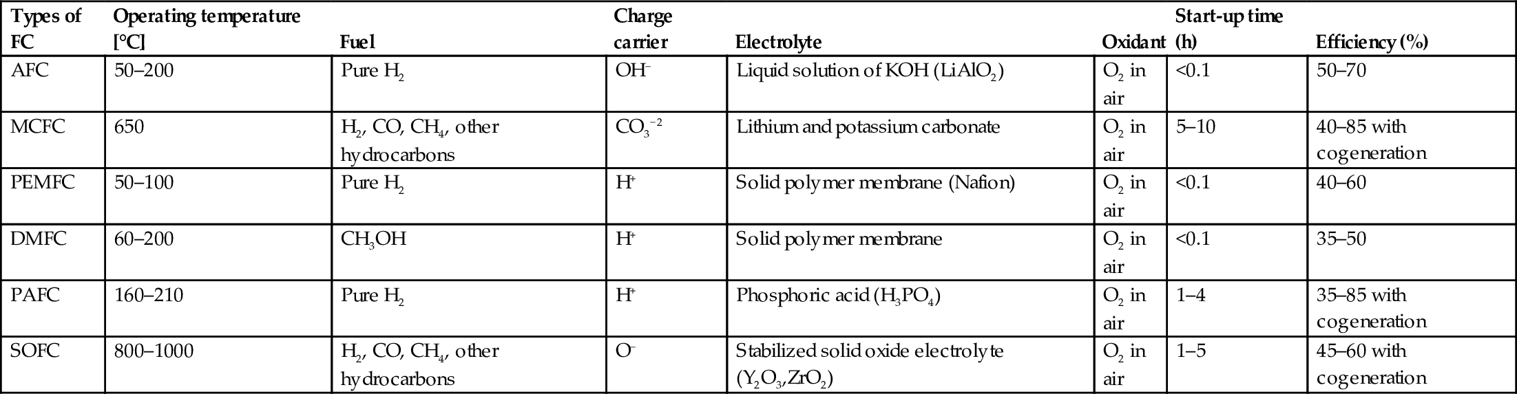
The classification with some technical characteristics is shown in Table 33.1.
Table 33.1
Main types of fuel cells with some technical characteristics [5,25,37,40,41]
| Types of FC | Operating temperature [°C] | Fuel | Charge carrier | Electrolyte | Oxidant | Start-up time (h) | Efficiency (%) |
| AFC | 50–200 | Pure H2 | OH− | Liquid solution of KOH (LiAlO2) | O2 in air | <0.1 | 50–70 |
| MCFC | 650 | H2, CO, CH4, other hydrocarbons | CO3−2 | Lithium and potassium carbonate | O2 in air | 5–10 | 40–85 with cogeneration |
| PEMFC | 50–100 | Pure H2 | H+ | Solid polymer membrane (Nafion) | O2 in air | <0.1 | 40–60 |
| DMFC | 60–200 | CH3OH | H+ | Solid polymer membrane | O2 in air | <0.1 | 35–50 |
| PAFC | 160–210 | Pure H2 | H+ | Phosphoric acid (H3PO4) | O2 in air | 1–4 | 35–85 with cogeneration |
| SOFC | 800–1000 | H2, CO, CH4, other hydrocarbons | O− | Stabilized solid oxide electrolyte (Y2O3,ZrO2) | O2 in air | 1–5 | 45–60 with cogeneration |
33.3.1 Alkaline Fuel Cell
Alkaline fuel-cell system is one of the first developed fuel-cell technology with the simplest structure. It is the first type widely used on space applications [37,41]. AFCs use a liquid solution of potassium hydroxide (KOH) as an electrolyte that conducts ions between two electrodes: anode and cathode. Because the electrolyte is alkaline, the ion conduction mechanism has differences from PEMFCs [24]. At the basic structure of AFCs as given in Fig. 33.3, at the anode side, hydrogen undergoes oxidation reaction that turns hydrogen into a positively charged ion and negatively charged electron. The negatively charged electrons travel through an external circuit that generates electricity and unifies with oxygen atoms at the cathode side [42]. The alkaline electrolyte only lets the composed hydroxyl (OH−) go through the anode side. By this reaction, hydrogen ions and hydroxyl reunite producing water. Eventually, water, heat and the electricity will be obtained.

Some key advantages of AFC systems can be specified as [43] the following:
• Low operation temperatures (50–200°C)
• Quick start-up range (<0.1 h)
• High efficiency (50%–70%)
• Low catalyst requirement reducing content costs
• Simple structure
• Low weight and volume
Some key disadvantages of AFC systems can be specified as [13,43–45] the following:
• Short operating life since they use a liquid solution of potassium hydroxide (KOH) as an electrolyte that is highly corrosive, thus eroding its parts
• Required oxygen must be provided after purification since they are very intolerant to carbon dioxide
• High cost for commercialized applications and current R&D studies are focusing on reducing costs
33.3.2 Molten Carbonate Fuel Cell
The main principles of MCFCs are based on SOFCs and the other types of fuel cells. In the mid-1960s, Texas Instruments developed several MCFCs for US Army that led to a widespread use of MCFCs in the field [43].
MCFCs use lithium potassium carbonate salts as an electrolyte as shown in Fig. 33.4. They operate at high temperatures (650°C); therefore, catalysts can be made of low-priced metals to reduce cost, and the heat/exhaust can be utilized [37]. If the heat/exhaust can be utilized (with CHP), the efficiencies of MCFCs can be increased from 60% to 85%. Additionally, higher temperature makes the FC system more tolerant to poisoning (carbon monoxide) than lower temperatures. These systems can use either carbon dioxide or oxygen as a fuel. Currently, there are many molten carbonate systems available with capacities ranging from 100 kW up to 2 MW.

MCFCs do not demand an external reformer; thus, the primary fuel used may not be hydrogen gas. The basic components of natural gas, methane, and steam are processed at a reformer in the MCFC system, and electricity will be produced. The internal reformer reduces the costs compared with the other FC technologies with external reformers.
Some key advantages of MCFC systems are specified below [43,46]:
• Using the fuel converted in the system
• Producing so much heat/exhaust that can be cogenerated
• High efficiencies
• Relatively fast response to load changes in steady-state conditions
• Require low-cost catalysts
• Lower sensitivity to poisoning
Some key disadvantages of MCFCs include the following [46]:
• Slow start-up range (5–10 h)
• Demand redesigning with more resistant components to corrosion
• Problems in contenting the liquid electrolyte in the structure
• Requirement of preheating before starting work
• Short operating life especially when using for high-power production systems
33.3.3 Polymer Electrolyte Fuel Cell
Among the various next generation power supplies, the polymer electrolytes or PEMFCs have been found to be one of the most promising energy sources due to their high efficiencies and environment-friendly operations [47].
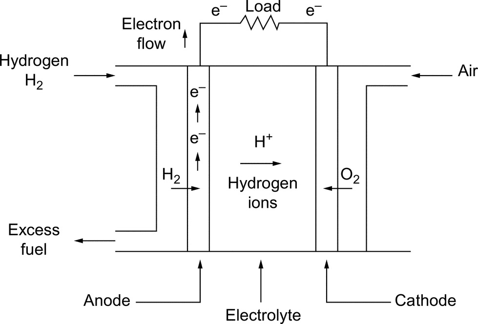
The basic structure of PEMFC, shown in Fig. 33.5, consists of three segments: the anode (negative characteristic electrode), the cathode (positive characteristic electrode), and the electrolyte membrane sandwiched between the two that allows only positively charged ions/protons to move between the two electrodes. The anode and the cathode have a catalyst, which speeds up the reactions at the electrode. Hydrogen goes to the anode side, and oxygen from the air flow goes to the cathode side. At the anode side, hydrogen undergoes oxidation reaction that turns hydrogen into a positively charged ion and negatively charged electron. After the reaction, protons are being transferred from anode to cathode through the electrolyte membrane, while the electrons travel through an external circuit. When the ions/protons reach the second electrode cathode, they will unify again with electrons and react with oxygen to form water. Eventually, electricity, water, and heat will be generated [39].
Some key advantages of PEMFCs include the following [16]:
• Low operation temperatures (50–100°C)
• Quick start-up range (<0.1 h)
• High efficiencies (40%–60%)
• Structure of electrolytes is more reliable, secure, and stable than other FCs
• High power density is the highest among all the available types of FCs
• High tolerance capability to differential pressures of the reactants
• Robust and simple structural design
Some key disadvantages of PEMFCs are listed below:
• Possess a structure highly depending on the purity of hydrogen
• Very poor tolerance to carbon monoxide and sulfur particles
• Gases require to be moisturized before reacting
• Comprised of a fairly expensive platinum catalyst and a solid polymer membrane
PEMFCs are a good candidate to substitute conventional technologies with their higher efficiencies and lower environmental impacts. The cost of PEMFCs is expected to down to consumer affordable levels in the near future [13].
Many advantages of PEMFCs, including fast response time, low operating temperature, high power density, and life cycling, have made the PEMFCs attractive and promising energy devices from the transportation and mobile applications to stationary applications as a distributed generation [5,16]. Therefore, lots of big companies such as Ballard, UTC, Nuvera, PlugPower, General Electric, Toshiba, and Sanyo produce PEMFCs commercially. Leading automaker companies such as Honda, Toyota, Daimler-Chrysler, General Motors, BMW, Nissan, Ford, Hyundai, and Renault and worldwide brand-mark companies like Samsung and IBM use this shining technology for their own commercial applications [48].
33.3.4 Direct Methanol Fuel Cell
FCs either use hydrogen directly or reform hydrocarbon fuels like methanol, which is the simplest organic fuel that can be most economically and efficiently produced from relatively plentiful fossil fuel [24]. Thus, the operation of the DMFC is based on oxidation of water mixed with methanol. After the oxidation, methanol goes to the FC anode side [37]. DMFCs use a liquid fuel methanol, which is easier to transport for public using with current infrastructure [41]. DMFCs are often used to supply power for portable electronics and emergency power supply.
Recently, concerns about the poisonous effects of methanol have emerged; thus, companies prefer using ethanol instead of methanol [37]. DMFCs have immature technology, low power density, slow power response, and low efficiency compared with direct hydrogen FCs [24].
33.3.5 Phosphoric Acid Fuel Cell
Phosphoric acid fuel cell is the first developed FC technology and first to be used commercially. They are considered as first generation of modern FC. PAFCs use liquid phosphoric acid as an electrolyte. The PAFC systems have about 40% energy production efficiency and high operating temperatures (150–220°C) [42]. With cogeneration of heat/exhaust, the efficiency can be increased up to 85% [43]. Currently, there are PAFCs with capacities ranging from 200 kW to 11 MW. Necessary improvements for widespread use of PAFCs will require reducing the operating cost while increasing the operating life.
These FC systems have a drawback of weight; therefore, these FCs are not preferable on transport applications. Some key advantages of PAFC systems can be specified as follows [43,46]:
• Tolerant till 30% carbon dioxide content, hence direct usage of atmosphere air
• High efficiency (85%) with cogeneration of heat/exhaust (CHP)
• Operate trouble-free at temperatures (150–220°C)
Some key disadvantages of PAFCs include the following [42,43]:
• Low tolerant to carbon monoxide component
• Exhausting water content can damage acidic electrolyte (corrosion)
• Massive and heavy structure
• Requirement of external reformer
• Requirement of preheating before starting to operate
33.3.6 Solid Oxide Fuel Cell
SOFCs operate at high temperatures (700–1000°C), and every single solid oxide cell produces 0.8–1 V voltages [43]. The heat/exhaust (around 500–850°C) generated by SOFCs is attractive for cogeneration. SOFC systems are currently used in stationary applications such as backup power units. Furthermore, recent R&D studies are focusing on feasibility of SOFCs at transportation appliances [49,50].
Solid oxide fuel cells are promising with their inherent advantages for industrial applications such as its independence from pure fuel. Therefore, hydrogen and CO, CH4, and other hydrocarbons can be used as fuel [37] in a SOFC. Since SOFCs operate at high temperatures, these systems can use low-cost catalyst components to enhance operational performance. SOFCs use a solid electrolyte, generally a ceramic material called yttria-stabilized zirconia (YSZ). Because the electrolyte does not involve a liquid-phased reaction, a problem such as fuel flooding does not occur. Also, SOFCs can be manufactured for many configurations, although other FC types with liquid electrolyte cannot [46].
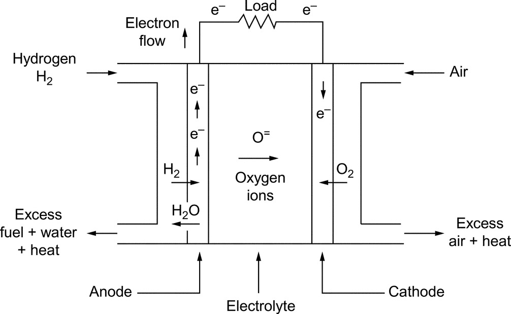
In SOFCs, fuel is supplied to the anode side, and oxygen from the air flow goes to the cathode side as shown in Fig. 33.6. At the anode side, hydrogen undergoes oxidation reaction that turns hydrogen into a positively charged ion and negatively charged electron. The separated electrons travel through an external circuit from anode to cathode to produce electricity and oxygen atoms absorb the electrons. The solid electrolyte membrane only permits the transition of negative charged oxygen ions from cathode to anode. When oxygen ions reach anode, they react with hydrogen ions to form water.
SOFCs have about 45% efficiency that can reach 85% by capturing and utilizing the heat/exhaust. Additionally, the SOFC systems have low gas emissions [51].
Some key advantages of SOFC systems can be specified as follows [42,45,46]:
• Producing massive amount of heat/exhaust that can be utilized
• Fast chemical reactions
• High efficiency
• The solid electrolyte is more reliable than a liquid electrolyte
• Nonrequirement of external reformer
• No corrosion problems
Some disadvantages of SOFC systems include the following:
• Requirement of R&D studies on decreasing volumetric and gravimetric parameters
• Low tolerant to sulfur element
• Requirement of long-term proof-of-concept studies
33.4 Fuel Cell System Components
Among the various types of fuel cells, PEMFC has drawn the most attention due to its simplicity, viability, quick start-up range, higher power density, long cycle life, and low operational temperature (80–100°C). Since PEMFCs are the best candidate for vehicular and commercial applications, in this section, PEMFC system components are discussed in detail.
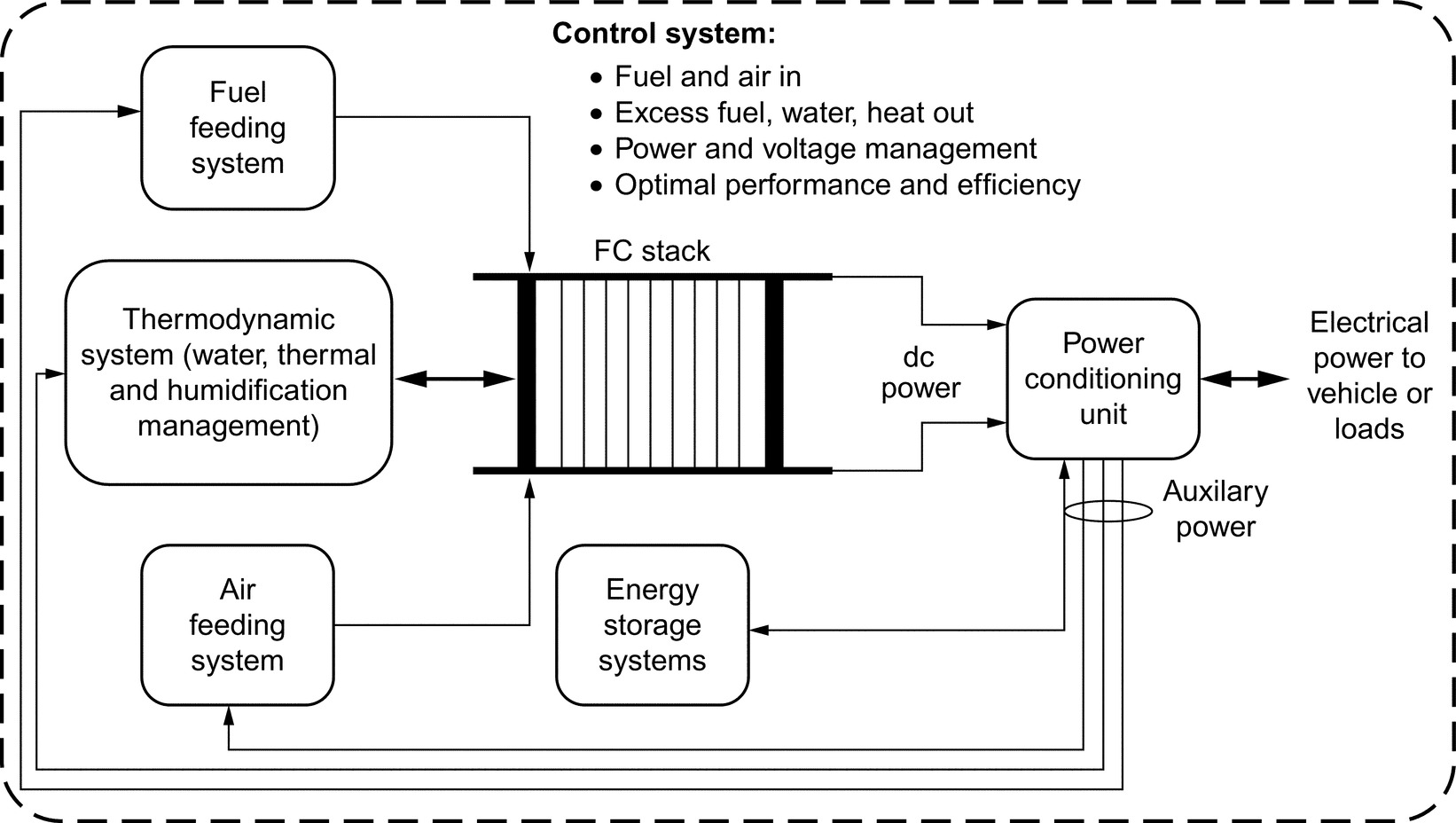
In practice, FC systems need auxiliaries (blowers, pumps, fans, ejectors, motors, turbines, compressors, valves, and regulators) to support their operation [24,52]. The main components of the FC system include the FC stack, fuel feeding, air compressors, humidifiers, power-conditioning unit with control systems, and energy storage system as shown in Fig. 33.7 [25]. All of these components work together to provide power to an electric load while regulating the proper amounts of fuel and ensuring system safety [52].
(i) Fuel cell stack. Although the FC stack is the main component of the fuel-cell system, for the required electric energy, all fuel-cell components must work in harmony. To that end, hydrogen fuel and air must be loaded into the stack as pressured gas. Thereafter, the excess hydrogen will be purged, and excess heat will be removed by circulating cooling water through the stacks during processing [23]. During operation, an FC produces dc electricity and water and heat through electrochemical process.
A fuel cell stack is made by assembling cells to deliver the required amount of voltage and power. Since a single cell produces less than 1 V, this voltage ratio is insufficient for most of the applications [21,41]. A single fuel cell consists of three metal plates called separators and two membrane electrode assembly (MEA) plates, which generates electricity. Innovative MEA design can provide effective and efficient fuel flow [21]. The cell generates electricity in the form of direct current (dc) by reacting hydrogen and oxygen in the air at the MEA.
The ideal potential of a hydrogen/oxygen FC under standard state conditions (25°C and 1 atm) is 1.229 V with liquid water product. However, the actual FC potential is lower than the ideal potential value due to the irreversible voltage drops that occurs in the FC system. There are three types of irreversible voltage drops, namely, activation overvoltage, ohmic overvoltage, and concentration overvoltage. At low current densities, the activation overvoltage is responsible for the voltage drop of the FC. Besides, concentration overvoltage becomes more significant at high current densities. The effects of these voltage drops and the corresponding variance of FC voltage can be seen from the FC polarization curve shown in Fig. 33.8 [53]. Operating FC in this linear region is quite important for ensuring overall system efficiency.
The fuel cell stack from combined assembling cells is the most important part of a fuel-cell power system, like an engine in the conventional vehicle. The FC stack provides the current required by governing of a fuel flow rate through the anode channels, that is, the fuel flow rate varies according to the system power requirements [5]. The auxiliaries of FC system also consume 10%–15% of the total power output of the fuel cell stack [24]. The amount of power produced by fuel cell and its performance depends upon several factors, such as cell size, operating temperature, reactant gas stoichiometric flow rates, pressure of gases supplied to the cell, and anode and cathode humidification parameters [41,52].

(ii) Fuel- and air-feeding systems. Automotive applications with onboard hydrogen storage tank have control systems consisting of pressure regulators, relative humidity, fuel purity grade, and fluid-dynamic conditions [23]. As mentioned before, FCs have some limitations to track fast load variations, such as acceleration and deceleration for vehicular application, due to their relative slow dynamics, which is defined as FC starvation and flooding phenomenon. Thus, to utilize an FC in dynamic applications, both the air- and fuel-feeding control systems must be well managed and supported by a proper fuel cell energy storage system. To improve FC performance and efficiency, design and control of the air compressor are very important in order to accumulate and efficiently remove water produced from the reaction [21,23,41]. However, some automakers like Hyundai use different design as near-ambient air pressure to provide oxygen to the FC stack [54].
(iii) Thermodynamic system. In an FC system, water management, thermal management, and humidification can be increased to optimize overall system performance and improve power generation [23]. These three components must be efficient and reliable for optimum functioning of overall system, which require proper design, control, and water balance. If these conditions cannot be achieved, problems such as membrane drying out, electrode flooding and conductivity inadequacy, and excess water accumulation in the anode side would occur [23,25].
(iv) Power-conditioning unit. Another part of FC system is the power-conditioning unit (PCU). Because an FC produces dc electric energy, it must be converted from unregulated low-voltage level (voltage varies in a wide range depending on the load current) to regulated high-voltage level using a dc/dc converter and/or inverted to alternating current (ac) using dc/ac inverter for ac electric loads/drivetrains. The power-conditioning unit in such a vehicular system is mainly composed of dc/dc converters and an inverter unit. The inverter and propulsion motor are emulated using the dc load bank; therefore, only dc/dc converters are designed and built. The dc/dc converters used in FCEV topologies are the essential power-train components as they allow load sharing between main energy source and energy storage systems (ESSs) by using PCU. For example, the FC power stage is assigned for a power-tracking process to supply the determined power value from the FC system. Besides, ESS power stage can be devoted to DC link voltage control. Both power tracking and DC link voltage control processes can be implemented using a controller. Thus, this hybrid system topology provides the capability of delivering the desired power value from the FC system while keeping the bus voltage at desired intervals [55]. The driving motor can either be ac or dc motors such as induction motors, permanent magnet brushless motors, and switched reluctance motors [56]. The proper response of the FC system to the overall load dynamics can be achieved by generating appropriate power-switching signals to the converters [47]. While these converters design and operate, they must be preferred with high voltage ratio, high efficiency, low electromagnetic interference (EMI), and high compactness while keeping low cost [37].
(v) Energy storage systems. A stand-alone FC system integrated into an automotive powertrain is not always sufficient to satisfy the load demands of a vehicle. Although FC systems exhibit good power capability during steady-state operation, the response of fuel cells during transient and instantaneous peak power demands is relatively poor. Therefore, when utilizing a PEMFC, it is recommended to associate it with an auxiliary power source to improve the dynamic performance of the whole system. There are many types of auxiliary units for compensating the slow response characteristics of the PEMFC unit and increasing the efficiency of the overall system. Energy storage units such as batteries, ultracapacitors (UCs), and flywheels, can be classified in the auxiliary power units group for use in hybrid systems including PEMFC. Specifically, not only energy storage units compensate the slow response phenomenon of PEMFC system, but also it provides the advantage of recovering the reusable kinetic energy that occurs in vehicular applications during braking periods. Thus, the consumption of hydrogen for FC units can be significantly decreased.
In many applications, batteries are utilized as ESS. Among the various existing rechargeable batteries, lithium-ion batteries appear to occupy a prime position in various aspects. A battery is needed in an FC system to supply power during the time after a change in the flow of reactants occurs. An auxiliary power source such as a battery bank can be used to improve the FC dynamics. In addition, the use of batteries reduces the size and cost of the FC, increases the lifetime, and avoids overloading. The battery bank supplies auxiliary power during cold start of the FC and supports peak demand periods or transient events. They also compensate the tracking delays of FC system. The state of charge (SoC) is an indicator showing the emptiness or fullness of the battery. The battery current can either be negative or positive, with respect to the mode of operation, for example, charging or discharging [57].
When the load power exceeds the maximum output of FC, battery starts to discharge through a converter located in the PCU and keeps discharging until the overloading ends. Also, if a step or ramp increase in the load demand occurs (even there is no overloading), battery bank helps the FC system until the FC power increases and matches the demanded power. The FC system has a relatively slow response in both step-up and step-down load conditions. When a step-down loading occurs, the output power of the FC slowly matches the reference power. In these conditions, the battery bank captures the differing power to successfully meet the load demands. These recaptured energies sometimes might not be sufficient to keep the battery SoC above a predefined level. Thus, another control loop is used to directly charge the battery bank from FC power plant with respect to the final SoC. The charge and discharge conditions of the battery are controlled with the aid of a dc/dc converter [57]. In the battery discharge current control, the key point is how good the FC power matches the active power requirement of the load. Thus, the positive difference between the FC reference power and the actual FC output power is processed to force the dc/dc converter to draw the reference current from the battery. The discharge current is limited using a saturation system to avoid battery overloading.
The battery can be charged when the FC reference power is above the power demand due to its slow response. While this can be evaluated as a naturally charging condition, another charging control loop is also employed. If all these conditions conforms the respective criteria, battery can be charged. In the battery charge current control, the key point is instantaneous SoC of the battery when compared with its nominal SoC. The battery charge current should be inversely proportional to the depth of discharge [57]. Also, the battery has some effect on meeting the reactive power demand. We can express the reactive power as the oscillating power between source and load buses. In systems including dc/ac conversion such as fuel cells, we observe that the reactive power oscillates between the reversible device (battery or UC) of the dc bus and the ac load bus. The reactive power passes through the antiparallel diodes of the inverter circuit to reach the rechargeable device and then passes to the load side through the next alternant. However, due to the reactive power losses on the contactors and the equivalent system impedance, there is always a dc power to be converted to the reactive power, which results in hydrogen consumption, stack dc voltage drop, and load bus voltage drop [57].
Ultracapacitors are also ESS devices that offer significantly better energy densities than conventional capacitors, better power densities than conventional batteries and can be constructed in modular and/or stackable format. The charge and discharge time of an UC varies from fractions of a second to several minutes, while providing maintenance-free operation. UCs provide the lowest cost per farad and extremely high cycling capability and prove to be environmentally safe [47]. The capacitance of UCs may vary from a few farads to several thousand farads per cell. Because of the aforementioned unique characteristics, UCs are utilized for a wide range of applications. Therefore, a UC bank can effectively serve as a cost-effective alternative to batteries, especially during short peak demand periods.
The natural structure of ultracapacitors is appropriate to meet transient and instantaneous peak power demands. The UC bank is designed to provide the difference between the load demand and the output power generated by the FC system. Without the UC bank, the FC system must supply all power demand, thus increasing the size and cost of the FC system.
The amount of energy drawn from the UC bank is directly proportional to the capacitance and the change in terminal voltage. The effective specific energy for a prescribed load can be supplied by various UC bank configurations. In practical applications, the required amount of terminal voltage and energy or the capacitance of UC storage system can be built using multiple UCs in series and parallel. The terminal voltage determines the number of capacitors, which must be connected in series to form a bank, and the total capacitance determines the number of capacitors, which must be connected in parallel in the bank. The natural structure of UC is appropriate to meet transient and instantaneous peak power demands.
As a result, while choosing an ESS, the following characteristics should be considered [5,57]: specific energy and energy density; electric power, that is, the electric load required; volume and mass; storage capacity; reliability; durability; safety; cost; recyclability; environmental impact; response time; efficiency; self-discharge rate/charging cycles and excess discharge; sensitivity to temperature; charge-discharge rate lifetime; environmental effects; investing/operating cost; maintenance; availability; design complexity/voltage range; life cycle; and recharge rate of storage element.
33.5 Fuel Cells in Automotive Applications
FCs offer many advantages over the internal combustion engines (ICE) for vehicular applications because they are energy efficient, clean, and fuel flexible. Today, FCs have become smaller, more powerful, and more durable [54]. Since FCEVs provide much better air quality, health problems, such as incidence of asthma and other chest complaints, will decrease [25]. Hydrogen FC systems have the potential to reach 60% peak efficiency [15]. Onboard the vehicle, conversion of hydrogen produces electricity for power train of vehicle and water. Hydrogen can be obtained from various sources with different methods [58]. Leading automobile industries are making every effort to make hydrogen-powered vehicles affordable, environment-friendly, and safe [25,41].
Automobiles, buses, scooters, golf cars, utility vehicles (such as forklifts and airport vehicles), locomotives, tramways, boats, airplanes, and underwater vehicles can be considered as some of the applications of PEMFC systems in transportation area [15]. In automobile systems, almost all major automakers have demonstrated prototypes and commercially available FC vehicles and announced future plans for production and commercialization in the near future. On the other hand, buses seem to be the most likely type of road vehicles for an early market introduction of the FC technology. Also, scooters may be a significant market for FC technologies, especially in developing countries. To conclude, the transportation area seems to be the most promising sector of PEMFC technology.
The need to reduce emissions through the improvement of vehicle efficiency and the depleting fossil fuels has motivated researchers to investigate alternatives to conventional ICE-based vehicular systems. Among the alternatives, FC-powered electric vehicles using hydrogen as fuel are considered as the ultimate route to achieving sustainable long-term alternative propulsion systems [16]. Hydrogen is an energy carrier with many important unique features. It is considered as the lightest, most efficient, and cleanest fuel. One of its unique features is that it can be converted to electricity in FCs through electrochemical processes with higher efficiencies than conversion of fossil fuels to mechanical energy in ICEs. Thus, this particular characteristic allows higher efficiency and practically null emission of polluting agents for FC-powered vehicles compared with ICE-based vehicular systems. Particularly, these efficiency and environmental friendliness advantages become more significant when renewable energy sources such as wind and solar are used for hydrogen production. In particular, passenger vehicles are mostly operated at part loads significantly below their rated power; thus, vehicle running in urban or suburban areas demands a small fraction of the rated FC power most of the time. Thus, the efficiency of the overall system becomes higher as the FC is operated most efficiently. This issue is exhibited by Villatico and Zuccari [59] by comparing the performance of FC and ICE in real driving cycles. Moreover, FC-based vehicles have medium- and long-term potential to be the mainstream vehicle in the future because they have almost zero emission and compatible driving range to ICE-based vehicles [1,5,55]. For real utilization of EVs, many features should be considered, such as performance, cold start, reliability, durability, cost, and fueling/charging times, availability, and infrastructure [13,18]. Both FC and battery EVs have similar components, like driving motors, power conditioners; also, they will coexist in the future. The FCEV is a promising solution because of faster refueling, cold starting, faster warming up to operating temperature and longer driving range features compared with BEV [24,25,60]. Generally, the FCEVs are proper for midsize and long-range vehicles, while the BEV is suitable for small-size and short-range vehicles [5].
Among the various available FC types, PEMFC is the most likely candidate for automotive applications, thanks to its several attractive features, such as low operating temperatures, relatively low cost and quick start-up, simplicity, viability, packaging under the hood of vehicle, and high efficiency [55]. However, the unsteady operation of a vehicle may not be appropriate for the usage of a sole FC system. Moreover, a FC system (in the power train of an automotive) needs to be equipped with the combination of ESS, driving motor, converters, and various auxiliary devices [23]. The power demand of a vehicle motor undergoes significant variations due to acceleration, changes in road surface and traffic conditions. Thus, a sole FC system may not totally satisfy the power demand of a vehicle due to the limitation of fuel cells to track fast load variations because of their slow response dynamics. Besides, load demand fluctuations in vehicle operation may cause fuel starvation, flooding, membrane drying, and pressure imbalance across the FC membrane, which may damage the FC stack and decreases its lifetime [61]. Moreover, an advanced energy management strategy is necessary to split the power demand of a vehicle in a suitable way for the onboard power sources in order to maximize the performance while promoting the fuel economy and endurance of hybrid system components.
33.5.1 Design Architectures for PEMFC Powered Hybridizations
In general, FCEVs are configured as series vehicles [60]. However, the architecture of a FCEV can be configured in series, series-parallel, and parallel. The selection of the hybrid power-train topology is very important for an efficient operation and better market penetration of FCEV systems. Effective and efficient power conversion technologies are strategic for the progress of FCEVs [62]. Interfacing the load/power-train unit requirements with the different operational modes of onboard generation and storage systems call for suitable power electronic converter configuration and control. The selection of power-conditioning unit for hybrid systems including PEMFC is based on some significant factors like lower cost, space requirement, compact structure, higher efficiency, electric isolation, and ripple-free and reliable operation [15,62].
Despite the fact that hybridization concept brings remarkable benefits, the main challenge is to find the appropriate combination of energy sources. Each energy source has unique characteristics and energy conversion efficiency. Thus, each combination is expected to show different performance, efficiency, and fuel/energy consumption. Moreover, in a hybrid topology, these energy sources can be connected to dc bus either directly or via a power converter. In case of utilizing a power converter, which allows higher flexibility in load sharing, an improved hydrogen economy may be expected. However, system efficiency may decrease due to additional conversion stage, which might worsen the equivalent fuel economy.
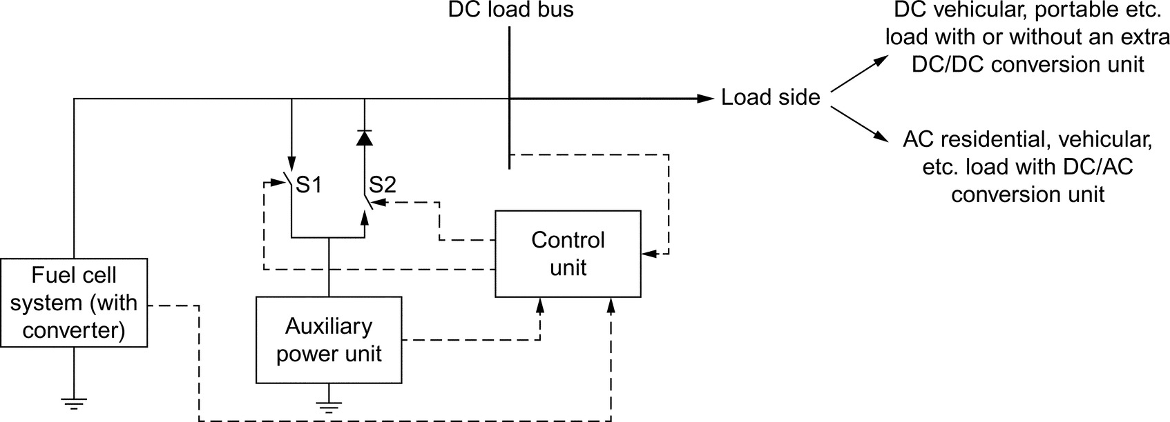
Considering the abovementioned factors and the load/drivetrain requirements, various topologies may be used for the operation of PEMFC hybrid systems. One of the simplest architectures for the parallel operation of PEMFC hybrid systems includes the direct integration of PEMFC system with the auxiliary power unit as shown in Fig. 33.9. During low power demand, the FC system generates up to its load limit, and the excess energy between the load demand and the FC output power is used to charge the auxiliary unit. In this period, the S1 switch is closed, and S2 switch is open. During high-power-demand periods, both the FC system and the auxiliary units supply the load demand. During this period, S1 switch is kept open, and S2 switch is closed. The direct integration topology is attractive, because it does not require a high-power dc/dc converter; thus, the complexity, cost, weight, and volume of the system are significantly reduced [15]. For example, the UC system integration can be achieved with or without power electronic converter via series and parallel connection. Because of the high specific power and power density of UC bank, it may be possible to eliminate the dc/dc converter for voltage regulation so that it can deliver higher output. This topology is proposed by Honda [63] for a combined PEMFC-/UC-powered vehicular system. Also, the direct integration of the FC with the UC bank is possible for relatively low-voltage applications with a dc bus of less than 50 V [64]. The UC bank and the load terminal voltages depend on the FC system terminal voltage, which prevents the power capability of the UC bank from being fully utilized. Therefore, the UC bank size is restricted by the terminal voltage of the FC system, as in the battery/UC hybrid system of Ref. [65].
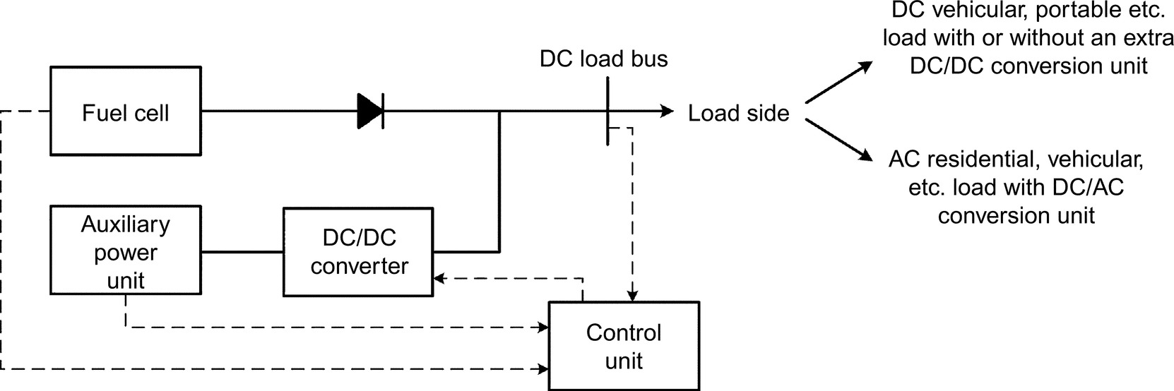
Different designs of a topology with only one dc/dc converter unit are shown in Figs. 33.10 and 33.11. The topology in Fig. 33.10 regulates the output power of the FC system, while the rest of the energy between the load demand and the FC output power is naturally supplied by the auxiliary unit. Besides, the topology in Fig. 33.11 is based on the regulation of the auxiliary system output power or the regulation of the DC bus voltage. There are many studies in the literature using these two topologies. Some previous studies on these topologies are reviewed and summarized in Ref. [15].

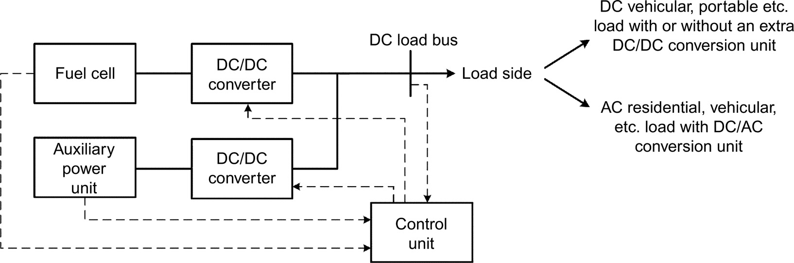
The most common topology for hybrid systems is composed of multiple dc/dc converters as shown in Fig. 33.12. In this kind of topology, the dc/dc converter of one of the available power sources is employed for the dc bus voltage regulation, which is called voltage-oriented-control, and the rest of the converters are controlled for power tracking by power-oriented-control methodology. Thus, the proposed power-conditioning unit provides the capability of delivering the desired power value from the hybrid power sources while keeping the bus voltage at a desired level. Additional architectures for the usage of multiple converter topologies for transportation area are available in Refs. [53,66–70].
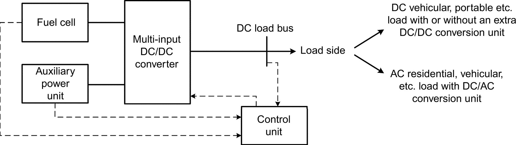
Combining the features of multiple converter-based topology, some researchers focused on utilizing multiple-input single-output design architecture as depicted in Fig. 33.13. This topology provides the advantage of reduced number of elements (multiple inputs of power sources can be connected to a dc bus via only one output capacitor) used in power electronics interface design. For example, Ferreira et al. [71], Perez et al. [72], and Napoli et al. [73] utilized the multi-input converter topology for an electric vehicular system consisting of PEMFC, battery, and UC.
The design of the abovementioned single- or multi-input converters can be realized as insulated or uninsulated, unidirectional, or bidirectional according to the area of application. The basic uninsulated unidirectional and bidirectional dc/dc converter topologies are shown in Fig. 33.14. The proposed multi-input and bidirectional converter-based PCU offers the following advantages:

• Voltage levels of the input power sources can be different.
• The input sources can deliver the requested power individually and simultaneously.
• Electrically isolation prevents damage on input sources.
• The proposed PCU can work bidirectionally, that is, the power can flow in either direction between individual input and output.
However, there are different advanced, more advantageous but complex topologies developed by power electronics researchers [15].
33.5.2 Vehicular Power Control Strategy and Energy Management
Due to the different characteristics of multiple power sources, the efficiency and the fuel economy of hybrid systems mainly depend on proper energy management strategy (EMS), which is very important for PEMFC-powered hybrid systems.
An FCEV energy control system must provide good acceleration and high recovery of braking energy. The power sharing between the FC system and energy storage system (battery or UC bank) is determined according to the load sharing and control algorithm. Main requirements of the control algorithm are satisfaction of the power demand and management of the power flow in accordance with efficient operation of the different power sources. Coupled with this, the control system should utilize the FC system and energy storage system to match the vehicle load profile by considering different features of power sources.
Since stable operation of the FC system is vital for efficiency, lifetime and cost, FC system should deliver the base load power without responding to peak power demand. Another purpose of the control system is to adopt the battery or UC bank in stabilizing the dc link voltage. This enables power transfer to/from battery or UC bank and improves the driving performance.
Hybrid systems can provide improved efficiency when a well-designed energy splitting algorithm that considers the individual characteristics of each hybrid system is applied. There are many techniques for energy management that have been investigated in the literature, such as intelligence-based strategies, optimization-based strategies, and frequency decoupling strategies [74].
33.5.2.1 Intelligence-based Energy Management
Recently, many intelligence-based energy management strategies such as fuzzy logic, and neural networks for use in PEMFC-powered systems, have been reported in the literature [15]. Among them, fuzzy logic controller (FLC)-based methodology plays a dominant role due to its independence of a full mathematical plant model and training procedure. Nonlinearity and difficulties in proper identification of parameters of the plant mathematical models limit the use of model-based conventional control approaches.
Fuzzy logic provides suitable structure compared with conventional control methods especially for the systems comprising nonlinear behaviors where an overall mathematical model is difficult to obtain. Moreover, there is no need for historical data, which is an important advantage over other types of intelligent controllers such as neural networks. Thus, FLC provides a suitable structure especially for systems composed of nonlinear behaviors.
In the literature, many researchers applied fuzzy logic approach for hybrid systems with PEMFC for different applications. Among them, Gao et al. [75] provided the power distribution in a hydrogen-powered hybrid bus composed of PEMFC as the main power source and battery/UC combination as the auxiliary unit. In [15], FLC utilized the SoC values of auxiliary units and the required power demand of the bus as inputs for determining the output power values of FC and UC systems. Erdinc et al. [53,67] regulated the energy management in PEMFC/UC and PEMFC-/battery-/UC-powered hybrid vehicular systems using fuzzy logic. The aforementioned architectures [53,67] utilized the SoC values of battery and/or UC units and a transient-free form of the vehicular power demand, provided by a load-sharing algorithm, based on standard drive cycles as inputs and gave the requested power value from PEMFC system as output. Li et al. [76] proposed a FLC design for a PEMFC/Battery hybrid system with a similar structure to Erdinc et al. [67]; however, they optimized the parameters of their FLC for an optimal energy control. As a contribution to the studies of Erdinc et al. [53,67] and Li et al. [76], Eren et al. [77] inserted the control of internal dynamics of PEMFC system in the fuzzy-logic-based energy management approach in order to provide a safe and efficient operation for PEMFC. Kisacikoglu et al. [78] directly controlled the duty cycles of the converters of PEMFC and UC as the outputs of the FLC in a PEMFC/UC hybrid vehicular system.
Another intelligent method used for the control of hybrid system is the neural network approach. Comparing neural network with one of the most popular intelligence-based technique, fuzzy logic, this quick-response capability provides a significant advantage. Fuzzy logic approach does not need a training procedure; however, the rule-based fuzzy structure makes it longer to respond compared with neural network approach. Thus, neural network control may be a competitive approach with fuzzy logic for some applications. Besides, the abovementioned features would lead the neural networks to solve complex problems precisely and flexibly and provide a suitable basis for the control of complex systems. Consequently, neural network has demonstrated remarkable success in control area [15].
33.5.2.2 Optimization Based Strategies for Energy Management
Power management and control system is very important for improving energy efficiency, vehicle performance, and for reducing the weight, size, and cost. Various flexible control methods and intelligent techniques are used for optimization, subject to system constraints. The power management system not only optimizes the available sources but also manages the load dynamically, based on the need and priority of the demand. In these types of energy management approaches, the optimal reference power signals for onboard power sources are calculated by the minimization of a cost function. This cost function generally represents the fuel consumption or emissions especially for vehicular applications. If this optimization is performed over a fixed driving cycle, a global optimum solution can be found. Many approaches such as optimal control theory, linear programming, dynamic or stochastic programming, genetic algorithm, simulated annealing, linear and nonlinear predictive model, and game theory are utilized for solving the aforementioned global optimization problem.
There is significant number of studies dealing with the energy management of an FC-powered hybrid system utilizing an optimization-based methodology [79,80]. For example, Rodatz et al. [79] presented an experimentally applied equivalent fuel consumption minimization strategy aiming at minimizing the hydrogen consumption while maintaining drivability in a PEMFC/UC hybrid vehicular system. Xu et al. [80] performed a similar optimization approach for an FC/battery hybrid bus. Similar fuel consumption minimization-based approaches were also utilized by Paladini et al. [81] for FC/battery/UC hybridization for a vehicle in a simulated environment.
33.5.2.3 Frequency Decoupling Based Energy Management Strategies
During the daily operation of a system, load transitions may occur frequently. The load power profile is a nonstationary signal and consists of transients. The wavelet transform can be effectively used for analyzing power transients in FCEV power demand profile, because of its ability to deal with nonstationary and/or transient signals. A given signal can be decomposed into transients and desired characteristics can be extracted simultaneously in both the time and frequency domain by using the wavelet transform (WT). The WT decomposes into various components at different time intervals and frequency bands as a windowing technique. In wavelet analysis, long windows are used at low frequencies, and short windows are also used at high frequencies.
One of the most popular mother wavelets is Haar wavelet for detecting and localizing of transients. The Haar basis has the shortest filter length in the time domain in comparison to other wavelet bases. Because of the abovementioned features, the Haar wavelet transform is the most suitable functions for filtering HEV power demand load profile, which consists of transients corresponding to sharp peak power demand. The transients of the HEV power demand signal is clearly observed from the short-term frequency and component magnitude changes.
For some applications like vehicular systems, these transient changes in load demand may occur significantly, which pose dynamic stress onto the FC membrane due to pressure oscillations and possible fuel starvation, which may reduce the lifetime of the FC system. Thus, to ensure FC lifetime prolongation by preventing the FC system from load changes with high frequencies, researchers applied different frequency decoupling techniques. The basic approach for this issue is inserting a transfer function for a delay with a suitable time constant (first-order low-pass filter). Liu et al. [82] proposed such a first-order filter for PEMFC system. Besides, some conventional filtering techniques like Butterworth high- and low-frequency filters have been utilized. These conventional filters decouple the main signal with a predefined cutoff frequency; thus, the FC system can be prevented from transient variations. However, the loss of important edge information is a significant phenomenon in conventional filtering techniques. Considering this issue, some researchers applied a wavelet-transform-based frequency decoupling strategy for PEMFC-powered systems. Wavelet transform is a signal processing method that is well known for its capability to treat transient signals. The advantage of wavelet analysis, as opposed to conventional techniques, is that wavelet transform decomposes a signal into a series of short duration waves or local basis functions (wavelets) on the time axis, which allows the analysis of local phenomena in signals consisting of many transients. Besides, wavelet transform provides a quadratic mirror filtering application and the loss of important edge information is minimized compared with conventional filtering techniques. Considering these features of wavelet transform, Uzunoglu and Alam [83] applied a wavelet-based energy management strategy for a PEMFC/UC hybrid vehicular system. A similar wavelet-based approach was utilized by Zhang et al. [66] for a PEMFC/battery/UC hybrid system.
With the abovementioned types of frequency decoupling strategies, the transients in the total power demand profile are captured, a safe operating condition for FC-based system can be provided and lifetime of the power sources can be extended [15].
33.5.2.4 Other Methods for Use in Energy Management
Existing methods in the literature in addition to the before mentioned techniques include basic linear proportional-integral (PI)-based approaches, complex adaptive control, robust control, and flatness-based control. A conventional linear PI controller is a basic approach that may be useful for use in real-time implementations of PEMFC systems. Many researchers utilized PI controller especially with a main supervisory controller design. As an example, Thounthong et al. [84,85] utilized a multiobjective PI-based linear technique for SoC sustaining and DC link voltage stabilization. Besides, Payman et al. [86] applied PI controller for the power electronics converter duty cycle determination in order to regulate the desired values of the system parameters determined by a nonlinear flatness-based supervisory control approach.
Another common approach, adaptive control technique, involves modifying the control law used by a controller to cope with the fact that the parameters of the system being controlled are slowly time-varying or uncertain. For example, as an aircraft flies, its mass will slowly decrease as a result of fuel consumption; we need a control law that adapts itself to such changing conditions. Adaptive control does not need a priori information about the bounds on these uncertain or time-varying parameters. Besides, adaptive control is precisely concerned with control law changes. There are mainly two types of adaptive controllers: feedforward and feedback adaptive controllers. There are many types of feedback adaptive controllers such as model reference adaptive controllers (MRACs) and model identification adaptive controllers (MIACs) that are reported in the literature [15].
Robust control methods, which explicitly deal with uncertainty, are designed to function properly so long as uncertain parameters or disturbances are within a typical limit. Robust methods aim to achieve robust performance and/or stability in the presence of bounded modeling errors. In contrast with an adaptive control policy, a robust control policy is static; rather than adapting to measurements of variations, the controller is designed to work assuming that certain variables will be unknown [15].
33.5.3 Current Status and Future Trends of Fuel Cell based Vehicles
Leading automakers have started to make their light-duty hydrogen FCEVs for testing and commercial applications. Available FCEVs are on the road in selected regions like California, Europe, Japan, where access to hydrogen stations are available. Some of these vehicle models include Honda FCV (2016), Toyota Mirai (2017), Mercedes-Benz B-Class F-Cell (2015), Hyundai Tuscon, and SUV (2016). All of these FCEVs uses 100 kW fuel cell stack. They also have quick refueling time of less than 10 min and driving range of around 200–300 mi [21,54,87–89].
The California Fuel Cell Partnership (CaFCP) plays a vital role in preparing to demonstrate and commercialize the vehicle technology of the twenty-first century. This organization is a unique collaborative of automakers, energy and FC technology companies, and government agencies. Currently CaFCP is focused on the marketization and industrialization and while emphasizing the importance for market introduction of FCEVs [90].
Although automakers have produced FC-based commercial vehicles, actually, they started to develop FCEV prototypes many years ago. For example, Toyota has developed various types of FCEVs, after it began its fuel-cell efforts in 1992. Ballard developed and demonstrated a hydrogen-fueled transit bus in 1993. GM demonstrated an FC/battery hybrid FCEV in 1998. Nearly 200 B-Class FC-based Mercedes-Benz vehicles have been with customers in the United States and Europe since 2010 [89]. AC Transit has the most comprehensive program to obtain real-world driving impressions and experiences and realize the earlier phase of the hydrogen FCEVs in North America [17,90]. The new Mercedes GLC F-CELL and next generation Honda FCEVs combine fuel cell and energy storage unit (lithium-ion battery) using plug-in hybrid technology that is planned to come to the market in 2017 and 2018, respectively [21,91].
Some governments (e.g., US and Japan) and automakers (e.g., Honda, Toyota, Daimler, Nissan, and Ford) are working together to support hydrogen infrastructure, public awareness, decrease operational costs of infrastructure firms. By cost reduction and mass production of competitive parts such as the FC stack, hydrogen, fueling stations, compact packaging, storage (battery and ultracapacitors), silicon carbide-based innovative power electronics, and electric motor technologies, these vehicles can be commercialized and introduced to the market for widespread use [18,21,37].
It is necessary to carry out further investigation on the performance, reliability, durability, and cost reduction of FC systems. FCEV design architecture plays a significant role while considering the performance, packaging, interior-space, efficiency, real-world performance, and durability issues. FCEV systems should be environmentally safe and commercially viable. Without doubt, technologies of a stable supply of highly pure hydrogen and inexpensive cell components are a prerequisite for market penetration of FC systems. In this case, since the number of renewable energy sources is increasing rapidly, new business models and marketing strategies can be developed. For example, the production of green hydrogen from renewable sources (biomass, biowaste, electrolyzers powered by photovoltaic, and wind energy systems) and also other feasible and viable hydrogen production methods can be used to feed the FCEVs and to balance the electric and gas grids under the smart grid concept [5,20]. Besides, as a part of sustainable energy and transportation chain, FCEVs, and their modular infrastructures like power inverter and hydrogen stations can contribute to the efficiency of the smart energy systems (as V2G, V2H, flexible load, storage, combined heat power, grid balancing, energy exchange, feed-in tariffs, and emerging application concepts). These kinds of EVs, like FCEVs, can also be used as an investment tool and as a major player of energy market in the future smart grids and smart cities.
Demonstration infrastructure should be sufficient for envisioned commercialization roadmap [5]. Demonstration projects and proof of concept experiments will act as a seed in addressing problems associated with practical applications, data collection for standardization, durability of FCEVs and accelerate awareness of using hydrogen in our daily life [5,17,21,92]. From the viewpoint of FCEVs market penetration, currently, there are limited commercial FCEVs, but in medium- and long-term periods, there will be huge numbers of FCEVs on the road depending on the abovementioned strategies of developed and developing countries. Thus, they can contribute significantly toward sustainable transportation and hydrogen chain.
33.5.4 Safety
Hydrogen FCs can revolutionize many sectors, since hydrogen is as safe as or even safer than other flammable fuels such as gasoline or natural gas. However, with the lack of professional design and management, hydrogen fuel cells pose several other risks that other flammable fuels do not.
Nowadays, FCEVs, hydrogen refueling stations and other values of hydrogen chain started to operate in different regions, despite pending answers to potential questions (How safe is hydrogen? What are potential hazards of hydrogen? Which improvements does it require to avoid danger?) [5]. Hazards and associated risks for hydrogen fuel cells should be considered by all stakeholders such as designers, regulators, and users in various situations when FCEVs are inoperable, in normal operation and in collision [5,16].
The main potential hazards can be listed as follows [5,16,21]:
• Hydrogen burns (rather than explosion)
• Higher flammability range
• Danger posed by invisible hydrogen flames (adding chemicals like odorant for required luminosity can provide an easier detection)
• Hard detection of hydrogen leak
• Higher tendency to leak since hydrogen is the smallest molecule (professional design may prevent leaks)
• Potential of hydrogen to asphyxiate people
• Frostbite/cold burns of liquid hydrogen
• Refueling station accidents
These hazards may be prevented or the impacts can be decreased with more R&D studies, administrative supports, efforts of all stakeholders, etc. For instance, Honda improved several designs to prevent FCEVs from collision impacts such as fastening bar as an impact resistant to prevent cells, straight frame structure to protect components, and load path structure to disperse the collision load and for efficient absorption of energy [21].
33.6 Conclusion
Almost all major companies have publicized ambitious plans to introduce hydrogen-powered vehicles in the market. Moreover, FCEVs are sold in selected regions with access to hydrogen stations. This vehicle type promises very clean operation and shows higher energy efficiency compared with conventional vehicles. When the FCEV technologies become mature, FCs can also be extended in many diverse areas from portable devices to silent heavy vehicles or aerospace applications. Besides, FCEVs and their infrastructure systems can also be used as a backup or integrated system for renewable energy sources.
In the near future, as a part of smart grid, FCEVs and hydrogen energy chain should be considered for sustainable development.